Trusted Business
Verified & Licensed
Virus Free Files
100% Safe Downloads
Secure Payment
SSL Protected
Instant Delivery
Available Immediately
MTU BR 2000 BR 4000 MDEC Engine Control System Stationary generator engines Technical Documentation Manual E531711-01E PDF DOWNLOAD
$27.95
MTU BR 2000 BR 4000 MDEC Engine Control System Stationary generator engines Technical Documentation Manual E531711-01E PDF DOWNLOAD
Instant PDF Download
Available immediately
Save to Your Device
Download & keep forever
Antivirus Scanned
100% virus-free
Trusted Worldwide
175,000+ customers
Description
MTU BR 2000 BR 4000 MDEC Engine Control System Stationary generator engines Technical Documentation Manual E531711-01E PDF DOWNLOAD
FILE DETAILS:
MTU BR 2000 BR 4000 MDEC Engine Control System Stationary generator engines Technical Documentation Manual E531711-01E PDF DOWNLOAD
Language : English
Pages : 170
Downloadable : Yes
File Type : PDF
IMAGES PREVIEW OF THE MANUAL:
Need help? Contact: [email protected]
https://vimeo.com/858928206?share=copy
DESCRIPTION:
MTU BR 2000 BR 4000 MDEC Engine Control System Stationary generator engines Technical Documentation Manual E531711-01E PDF DOWNLOAD
General Information about Documentation
Documentation Structure
| Documentation Part | Title/Contents | Target Group(s) |
|---|---|---|
| 1 | Structure and function | Operating personnel, etc. |
| 2 | Operation | Operating personnel |
| 3 | Maintenance and repair | Plant personnel |
| 4 | Service manual | Electronic service personnel |
| 5 | Illustrated parts catalog | Operating personnel, electronic service personnel, logistics personnel |
| 6 | Plant-specific configuration | Electronic service personnel, installation personnel, start-up personnel |
| 7 | Mechanical and electrical installation | Installation personnel (electromechanical/mechatronic engineer) |
| 8 | Initial start-up | Start-up personnel |
Note: Not all parts of the documentation are written for every product.
Required Knowledge
To understand each part of the documentation, we recommend reading the preceding parts, if applicable.
Reference Numbers and Reference Lines
Details in figures are provided with reference numbers and reference lines if necessary.
If reference is made in the text to a detail provided with a reference number, the figure number and, separated by an oblique, the reference number of the detail are written in brackets. Example: (5/2) means fig. 5, reference number 2.
A point at the end of the reference line means that the detail is visible in the figure.
An arrow at the end of the reference line indicates that the detail cannot be seen in the figure.
Symbols
The symbols used in safety notes are defined in the chapter “Safety requirements”.
TABLE OF CONTENTS:
MTU BR 2000 BR 4000 MDEC Engine Control System Stationary generator engines Technical Documentation Manual E531711-01E PDF DOWNLOAD
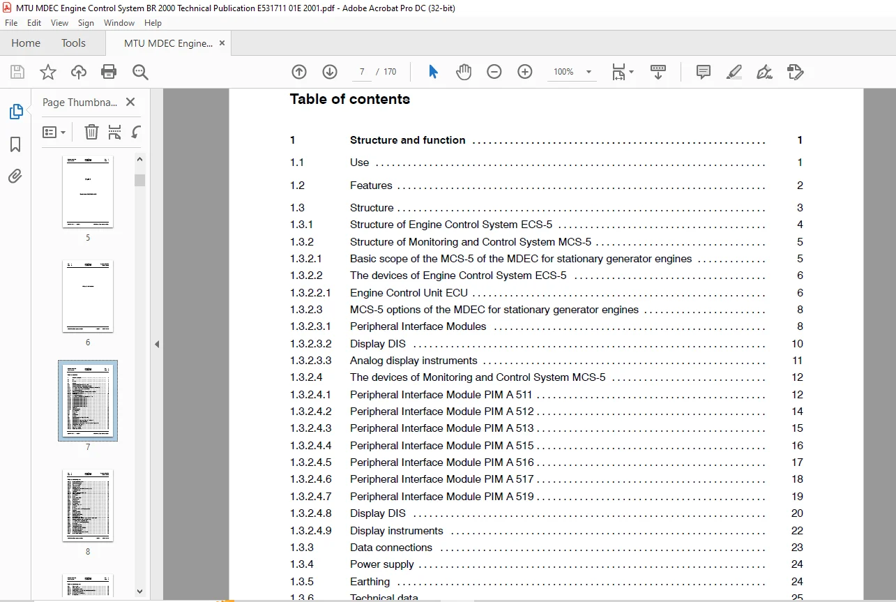
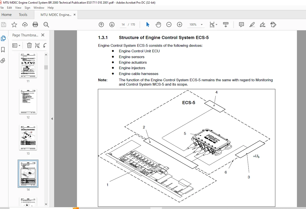
Title.............................................................................................  1
General information about documentation...........................................................  3
Part 1 - Structure and function...................................................................  5
	Table of Contents.............................................................................  7
	1 Structure and function...................................................................... 11
		1.1 Use................................................................................... 11
		1.2 Features.............................................................................. 12
		1.3 Structure............................................................................. 13
			1.3.1 Structure of Engine Control System ECS-5........................................ 14
			1.3.2 Structure of Monitoring and Control System MCS-5................................ 15
			1.3.2.1 Basic scope of the MCS-5 of the MDEC for stationary generator engines......... 15
			1.3.2.2 The devices of Engine Control System ECS-5.................................... 16
				1.3.2.2.1 Engine Control Unit ECU................................................. 16
			1.3.2.3 MCS-5 options of the MDEC for stationary generator engines.................... 18
				1.3.2.3.1 Peripheral Interface Modules............................................ 18
				1.3.2.3.2 Display DIS............................................................. 20
				1.3.2.3.3 Analog display instruments.............................................. 21
			1.3.2.4 The devices of Monitoring and Control System MCS-5............................ 22
				1.3.2.4.1 Peripheral Interface Module PIM A 511................................... 22
				1.3.2.4.2 Peripheral Interface Module PIM A 512................................... 24
				1.3.2.4.3 Peripheral Interface Module PIM A 513................................... 25
				1.3.2.4.4 Peripheral Interface Module PIM A 515................................... 26
				1.3.2.4.5 Peripheral Interface Module PIM A 516................................... 27
				1.3.2.4.6 Peripheral Interface Module PIM A 517................................... 28
				1.3.2.4.7 Peripheral Interface Module PIM A 519................................... 29
				1.3.2.4.8 Display DIS............................................................. 30
				1.3.2.4.9 Display instruments..................................................... 32
			1.3.3 Data connections................................................................ 33
			1.3.4 Power supply.................................................................... 34
			1.3.5 Earthing........................................................................ 34
			1.3.6 Technical data.................................................................. 35
		1.4 Functions............................................................................. 36
			1.4.1 Operating functions on display DIS (option)..................................... 36
			1.4.2 Display functions............................................................... 37
				1.4.2.1 Display functions of fault code display FCB in PIM A 511.................. 37
				1.4.2.2 Display functions of display DIS (option)................................. 38
				1.4.2.3 Display functions on the man-machine interface of the display (option).... 39
					1.4.2.3.1 General screen page structure....................................... 40
					1.4.2.3.2 Overview page structure............................................. 43
					1.4.2.3.3 System page stucture................................................ 44
					1.4.2.3.4 Graphic page structure.............................................. 45
					1.4.2.3.5 Measuring point list structure...................................... 46
					1.4.2.3.6 Contrast page structure............................................. 47
					1.4.2.3.7 Service page structure.............................................. 48
					1.4.2.3.8 Alarm page structure................................................ 49
					1.4.2.3.9 Help page structure................................................. 52
				1.4.2.4 Display functions of the display instruments (option)..................... 53
			1.4.3 Acquisition functions........................................................... 54
				1.4.3.1 Plant signals............................................................. 54
					1.4.3.1.1 Signals to Engine Control Unit ECU.................................. 54
				1.4.3.2 Engine signals............................................................ 56
					1.4.3.2.1 Sensors............................................................. 56
					1.4.3.2.2 Sensors on the engine............................................... 57
			1.4.4 Control functions............................................................... 60
				1.4.4.1 Engine start.............................................................. 61
					1.4.4.1.1 Normal engine start................................................. 61
					1.4.4.1.2 Engine restart...................................................... 62
					1.4.4.1.3 Emergency engine start.............................................. 62
				1.4.4.2 Engine stop............................................................... 63
				1.4.4.3 Override.................................................................. 63
				1.4.4.4 50 Hz/60 Hz switching on bi-frequency engines............................. 63
			1.4.5 Monitoring functions............................................................ 64
				1.4.5.1 Engine safety system...................................................... 64
				1.4.5.2 Combined alarm signalling................................................. 65
			1.4.6 Regulating functions............................................................ 66
				1.4.6.1 Speed/injection regulation................................................ 66
				1.4.6.2 Idle speed governor - maximum speed governor - feeding governor........... 67
				1.4.6.3 Common Rail injection system (series 4000 only)........................... 68
				1.4.6.4 PLN injection system (series 2000 only)................................... 69
				1.4.6.5 Angle measuring/determining engine timing................................. 70
				1.4.6.6 Speed droop............................................................... 71
					1.4.6.6.1 Speed droop calculation............................................. 71
					1.4.6.6.2 Switchable speed droop.............................................. 71
				1.4.6.7 Power limitation (quantity limitation).................................... 73
					1.4.6.7.1 Dynamic quantity limitation......................................... 73
				1.4.6.8 Speed setpoint handling................................................... 74
			1.4.7 Safety features................................................................. 75
				1.4.7.1 Safety shutdowns.......................................................... 75
					1.4.7.1.1 Integral Test System (ITS).......................................... 77
					1.4.7.1.2 Monitoring of the electronics in the Engine Control Unit ECU........ 77
					1.4.7.1.3 Sensor/actuator monitoring.......................................... 78
					1.4.7.1.4 Bus communication monitoring........................................ 78
				1.4.7.2 Overspeed test............................................................ 78
Part 2 - Operation................................................................................ 79
	Table of Contents............................................................................. 81
	2 Operation................................................................................... 83
		2.1 Safety requirements................................................................... 83
		2.2 Operating a display................................................................... 85
		2.3 Other operating procedures............................................................ 87
Part 3 - Maintenance and repair................................................................... 89
	Table of Contents............................................................................. 91
	3 Maintenance and repair...................................................................... 93
		3.1 Safety requirements................................................................... 93
		3.2 General information about this manual................................................. 95
			3.2.1 Task duration and personnel qualification....................................... 95
			3.2.2 Terminology..................................................................... 95
			3.2.3 Structure....................................................................... 96
		3.3 Tools, expedients and consumables..................................................... 97
			3.3.1 For care and maintenance........................................................ 97
			3.3.2 For repair...................................................................... 97
			3.3.3 Troubleshooting devices......................................................... 98
		3.4 Malfunctions..........................................................................100
			3.4.1 Safety instructions.............................................................100
			3.4.2 Fault displays..................................................................101
				3.4.2.1 Replacing Engine Control Unit ECU.........................................132
					3.4.2.1.1 Removing the housing of Engine Control Unit ECU from the engine.....134
					3.4.2.1.2 Opening the cover on Engine Control Unit ECU........................135
					3.4.2.1.3 Transferring memory modules in Engine Control Unit ECU..............136
					3.4.2.1.4 Fitting the cover on Engine Control Unit ECU........................138
					3.4.2.1.5 Mounting the housing of Engine Control Unit ECU on the engine.......139
				3.4.2.2 Using the MDEC simulator..................................................141
		3.5 Maintenance...........................................................................143
			3.5.1 Maintenance overview............................................................143
			3.5.2 Visual inspection, mechanical testing and cleaning..............................144
				3.5.2.1 Cleaning device(s) externally.............................................145
		3.6 Structure of Engine Control Unit ECU 4................................................146
			3.6.1 External structure..............................................................146
			3.6.2 Internal structure..............................................................148
A Abbreviations...................................................................................151
B Connector pin assignment........................................................................153
C ECU channel input circuitry.....................................................................165
PLEASE NOTE:
- This is the same manual used by the dealers to diagnose and troubleshoot your vehicle
- You will be directed to the download page as soon as the purchase is completed. The whole payment and downloading process will take anywhere between 2-5 minutes
- Need any other service / repair / parts manual, please feel free to contact [email protected] . We still have 50,000 manuals unlisted
G.P