Trusted Business
Verified & Licensed
Virus Free Files
100% Safe Downloads
Secure Payment
SSL Protected
Instant Delivery
Available Immediately

MTU Diesel Engine 12 V 4000 G23 G43 G63 G83 16 V 4000 G23 G43 G63 G83 G83L Operating Instructions Manual M015710-04E PDF DOWNLOAD
$26.95
MTU Diesel Engine 12 V 4000 G23 G43 G63 G83 16 V 4000 G23 G43 G63 G83 G83L Operating Instructions Manual M015710-04E PDF DOWNLOAD
Instant PDF Download
Available immediately
Save to Your Device
Download & keep forever
Antivirus Scanned
100% virus-free
Trusted Worldwide
175,000+ customers
Description
MTU Diesel Engine 12 V 4000 G23 G43 G63 G83 16 V 4000 G23 G43 G63 G83 G83L Operating Instructions Manual M015710-04E PDF DOWNLOAD
FILE DETAILS:
MTU Diesel Engine 12 V 4000 G23 G43 G63 G83 16 V 4000 G23 G43 G63 G83 G83L Operating Instructions Manual M015710-04E PDF DOWNLOAD
Language : English
Pages : 211
Downloadable : Yes
File Type : PDF
IMAGES PREVIEW OF THE MANUAL:
TABLE OF CONTENTS:
MTU Diesel Engine 12 V 4000 G23 G43 G63 G83 16 V 4000 G23 G43 G63 G83 G83L Operating Instructions Manual M015710-04E PDF DOWNLOAD
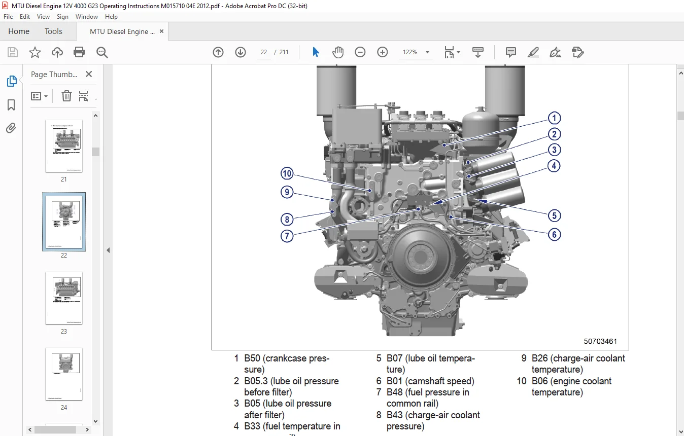
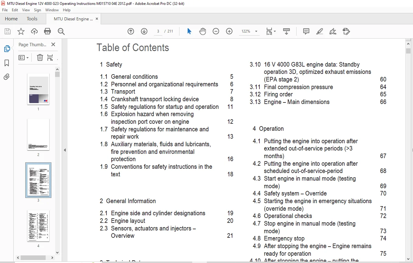
Operating Instructions....................................................................................................  1
	Table of Contents.....................................................................................................  3
	1 Safety..............................................................................................................  5
		1.1 General conditions............................................................................................  5
		1.2 Personnel and organizational requirements.....................................................................  6
		1.3 Transport.....................................................................................................  7
		1.4 Crankshaft transport locking device...........................................................................  8
		1.5 Safety regulations for startup and operation.................................................................. 11
		1.6 Explosion hazard when removing inspection port cover on engine................................................ 12
		1.7 Safety regulations for maintenance and repair work............................................................ 13
		1.8 Auxiliary materials, fluids and lubricants, fire prevention and environmental protection...................... 16
		1.9 Conventions for safety instructions in the text............................................................... 18
	2 General Information................................................................................................. 19
		2.1 Engine side and cylinder designations......................................................................... 19
		2.2 Engine layout................................................................................................. 20
		2.3 Sensors, actuators and injectors – Overview................................................................... 21
	3 Technical Data...................................................................................................... 25
		3.1 16 V 4000 Gx3 engine data: Continuous operation 3A, optimized fuel consumption................................ 25
		3.2 12 V 4000 Gx3 engine data: Continuous operation, variable 3B, optimized fuel consumption...................... 28
		3.3 12 V 4000 Gx3 engine data: Continuous operation, variable 3B, optimized exhaust emissions (TA-Luft)........... 32
		3.4 16 V 4000 Gx3 engine data: Continuous operation, variable 3B, optimized fuel consumption...................... 36
		3.5 12/16 V 4000 Gx3 engine data: Continuous operation, variable 3B, optimized exhaust emissions (EPA stage 2).... 40
		3.6 12V 4000 Gx3 engine data: Standby operation 3D, optimized fuel consumption.................................... 44
		3.7 16 V 4000 Gx3 engine data: Standby operation 3D, optimized fuel consumption................................... 48
		3.8 12/16 V 4000 Gx3 engine data: Standby operation 3D, optimized exhaust emissions (EPA stage 2)................. 52
		3.9 16 V 4000 G83L engine data: Standby operation 3D, optimized fuel consumption.................................. 56
		3.10 16 V 4000 G83L engine data: Standby operation 3D, optimized exhaust emissions (EPA stage 2).................. 60
		3.11 Final compression pressure................................................................................... 64
		3.12 Firing order................................................................................................. 65
		3.13 Engine – Main dimensions..................................................................................... 66
	4 Operation........................................................................................................... 67
		4.1 Putting the engine into operation after extended out-of-service periods (>3 months)........................... 67
		4.2 Putting the engine into operation after scheduled out-of-service-period....................................... 68
		4.3 Start engine in manual mode (testing mode).................................................................... 69
		4.4 Safety system – Override...................................................................................... 70
		4.5 Starting the engine in emergency situations (override mode)................................................... 71
		4.6 Operational checks............................................................................................ 72
		4.7 Stop engine in manual mode (testing mode)..................................................................... 73
		4.8 Emergency stop................................................................................................ 74
		4.9 After stopping the engine – Engine remains ready for operation................................................ 75
		4.10 After stopping the engine – putting the engine out of service................................................ 76
		4.11 Plant cleaning............................................................................................... 77
	5 Maintenance......................................................................................................... 78
		5.1 Maintenance task reference table [QL1]........................................................................ 78
	6 Troubleshooting..................................................................................................... 79
		6.1 Troubleshooting............................................................................................... 79
		6.2 Engine governor ADEC (ECU 7) for Series 4000 genset engines – Fault messages.................................. 82
	7 Task Description....................................................................................................131
		7.1 Engine........................................................................................................131
			7.1.1 Engine – Barring manually...............................................................................131
			7.1.2 Engine – Barring with starting system...................................................................132
			7.1.3 Engine – Test run.......................................................................................133
		7.2 Cylinder Liner................................................................................................134
			7.2.1 Cylinder liner – Endoscopic examination.................................................................134
			7.2.2 Instructions and comments on endoscopic and visual examination of cylinder liners.......................136
		7.3 Crankcase Breather............................................................................................138
			7.3.1 Crankcase breather – Oil separator element replacement, diaphragm check and replacement.................138
		7.4 Valve Drive...................................................................................................140
			7.4.1 Valve gear – Lubrication................................................................................140
			7.4.2 Valve clearance – Check and adjustment..................................................................141
			7.4.3 Cylinder head cover – Removal and installation..........................................................144
		7.5 Injection Pump / HP Pump......................................................................................145
			7.5.1 HP pump – Filling with engine oil.......................................................................145
		7.6 Injection Valve / Injector....................................................................................146
			7.6.1 Injector – Replacement..................................................................................146
			7.6.2 Injector – Removal and installation.....................................................................147
		7.7 Fuel System...................................................................................................152
			7.7.1 Fuel system – Venting...................................................................................152
		7.8 Fuel Filter...................................................................................................153
			7.8.1 Fuel filter – Replacement...............................................................................153
			7.8.2 Fuel prefilter cleaning.................................................................................154
			7.8.3 Fuel prefilter – Differential pressure gauge check and adjustment.......................................155
			7.8.4 Fuel prefilter – Draining...............................................................................156
			7.8.5 Fuel prefilter – Flushing...............................................................................157
			7.8.6 Fuel prefilter – Filter element replacement.............................................................159
		7.9 Charge-Air Cooling............................................................................................161
			7.9.1 Intercooler – Checking condensate drain for coolant discharge and obstructions..........................161
		7.10 Air Filter...................................................................................................162
			7.10.1 Air filter – Replacement...............................................................................162
			7.10.2 Air filter – Check.....................................................................................163
			7.10.3 Air filter – Removal and installation..................................................................164
		7.11 Air Intake...................................................................................................165
			7.11.1 Service indicator – Signal ring position check (optional)..............................................165
		7.12 Starting Equipment...........................................................................................166
			7.12.1 Air starter – Manual operation.........................................................................166
		7.13 Lube Oil System, Lube Oil Circuit............................................................................167
			7.13.1 Engine oil – Change....................................................................................167
			7.13.2 Engine oil – Level check...............................................................................169
			7.13.3 Engine oil – Sample extraction and analysis............................................................170
		7.14 Oil Filtration / Cooling.....................................................................................171
			7.14.1 Engine oil filter – Replacement........................................................................171
			7.14.2 Oil indicator filter – Check...........................................................................172
			7.14.3 Centrifugal oil filter – Cleaning and filter sleeve replacement........................................174
		7.15 Coolant Circuit, General, High-Temperature Circuit...........................................................176
			7.15.1 Engine coolant – Level check...........................................................................176
			7.15.2 Engine coolant – Change................................................................................177
			7.15.3 Engine coolant – Draining..............................................................................178
			7.15.4 Engine coolant – Filling...............................................................................179
			7.15.5 Engine coolant pump – Relief bore check................................................................182
			7.15.6 Engine coolant – Sample extraction and analysis........................................................183
		7.16 Low-Temperature Circuit......................................................................................184
			7.16.1 Charge-air coolant – Level check.......................................................................184
			7.16.2 Charge-air coolant – Change............................................................................185
			7.16.3 Charge-air coolant – Draining..........................................................................186
			7.16.4 Charge-air coolant – Filling...........................................................................187
			7.16.5 Charge-air coolant pump – Relief bore check............................................................190
		7.17 Belt Drive...................................................................................................191
			7.17.1 Drive belt – Condition check...........................................................................191
		7.18 Battery-Charging Generator...................................................................................192
			7.18.1 Battery-charging generator drive – Drive belt tension adjustment.......................................192
			7.18.2 Battery-charging generator drive – Drive belt replacement..............................................193
		7.19 Engine Mounting / Support....................................................................................194
			7.19.1 Engine mounting – Check................................................................................194
		7.20 Wiring (General) for Engine/Gearbox/Unit.....................................................................195
			7.20.1 Engine wiring – Check..................................................................................195
		7.21 Accessories for (Electronic) Engine Governor / Control System................................................196
			7.21.1 Engine governor and connectors – Cleaning..............................................................196
			7.21.2 Engine governor – Checking plug-in connections.........................................................197
			7.21.3 ECU 7 engine governor – Removal and installation.......................................................198
	8 Appendix A..........................................................................................................199
		8.1 Abbreviations.................................................................................................199
		8.2 MTU contact persons/service partners..........................................................................202
	9 Appendix B..........................................................................................................203
		9.1 Special Tools.................................................................................................203
		9.2 Index.........................................................................................................209
Customer Support: [email protected]
https://vimeo.com/858589876?share=copy
DESCRIPTION:
MTU Diesel Engine 12 V 4000 G23 G43 G63 G83 16 V 4000 G23 G43 G63 G83 G83L Operating Instructions Manual M015710-04E PDF DOWNLOAD
SAFETY:
General Conditions
In addition to the instructions in this publication, the applicable country-specific legislation and other compulsory regulations regarding accident prevention and environmental protection must be observed. This state-of-the-art engine has been designed to meet all applicable laws and regulations. The engine may nevertheless present a risk of injury or damage in the following cases:
- Incorrect use
- Operation, maintenance, and repair by unqualified personnel
- Modifications or conversions
- Noncompliance with the Safety Instructions
Correct Use
The engine is intended solely for use in accordance with contractual agreements and the purpose envisaged for it on delivery. Any other use is considered improper use. The engine manufacturer accepts no liability whatsoever for resultant damage or injury in such case. The responsibility is borne by the user alone.
Correct use also includes observation of and compliance with the operating instructions and maintenance and repair specifications.
Modifications or Conversions
Unauthorized modifications to the engine represent a safety risk. MTU will accept no liability or warranty claims for any damage caused by unauthorized modifications or conversions.
Spare Parts
Only genuine MTU spare parts must be used to replace components or assemblies. MTU accepts no liability whatsoever for damage or injury resulting from the use of other spare parts, and the warranty shall be voided in such case.
Reworking Components
Repair or engine overhaul must be carried out in workshops authorized by MTU.
PLEASE NOTE:
- This is the same manual used by the dealers to diagnose and troubleshoot your vehicle
- You will be directed to the download page as soon as the purchase is completed. The whole payment and downloading process will take anywhere between 2-5 minutes
- Need any other service / repair / parts manual, please feel free to contact [email protected] . We still have 50,000 manuals unlisted
G.P