MTU Electronic Dialog System DiaSys®2.40SP1 Technical Documentation Manual E531920-04E PDF DOWNLOAD
$26.95
MTU Electronic Dialog System DiaSys®2.40SP1 Technical Documentation Manual E531920-04E PDF DOWNLOAD
Description
MTU Electronic Dialog System DiaSys®2.40SP1 Technical Documentation Manual E531920-04E PDF DOWNLOAD
FILE DETAILS:
MTU Electronic Dialog System DiaSys®2.40SP1 Technical Documentation Manual E531920-04E PDF DOWNLOAD
Language : English
Pages : 134
Downloadable : Yes
File Type : PDF
IMAGES PREVIEW OF THE MANUAL:
Questions? Email us: [email protected]
https://vimeo.com/858892008?share=copy
DESCRIPTION:
MTU Electronic Dialog System DiaSys®2.40SP1 Technical Documentation Manual E531920-04E PDF DOWNLOAD
INTRODUCTION:
General Information on the DiaSys Program
Use: The DiaSys program is required to communicate with various MTU controllers, RCS-5 remote control systems, and MCS-5 monitoring systems.
The main functions of the DiaSys program are:
- Data interchange with the central database.
- Adjusting the controller parameters.
- Data recorder function.
Note: For the most part, this manual contains information concerning the use of DiaSys together with governors. The functions described presuppose a hardware key level 1B (service/distributor). Menu screen functions are not described in this manual.
Neither the requirements of DiaSys software on the hardware (PC) nor the installation of this software is described in this document
TABLE OF CONTENTS:
MTU Electronic Dialog System DiaSys®2.40SP1 Technical Documentation Manual E531920-04E PDF DOWNLOAD
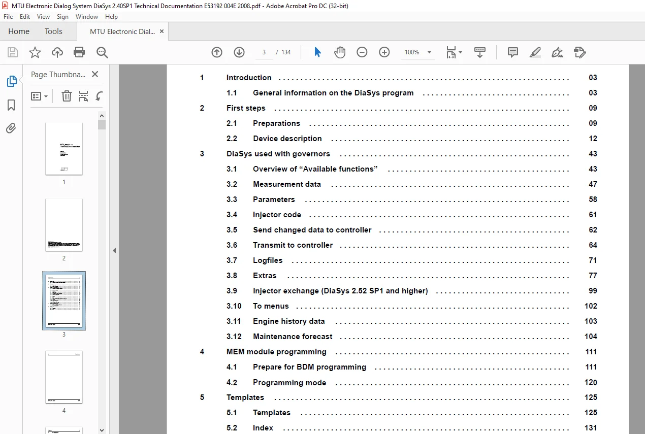
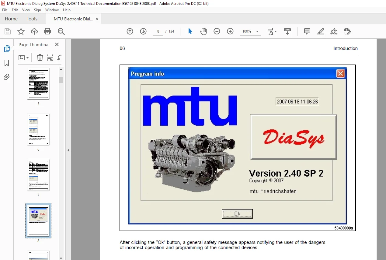
Title.............................................................................................................................  1
Table of Contents.................................................................................................................  3
1 Introduction....................................................................................................................  5
	1.1 General information on the DiaSys program.................................................................................  5
		Use.......................................................................................................................  5
		Terms and definitions.....................................................................................................  5
		Online mode...............................................................................................................  6
		Offline mode..............................................................................................................  6
		Hardware key..............................................................................................................  6
		Setting the CAN hardware used.............................................................................................  6
		Key combinations..........................................................................................................  7
		Explanations on Ctrl + Shift + A:.........................................................................................  7
		Program info..............................................................................................................  7
2 First steps..................................................................................................................... 11
	2.1 Preparations.............................................................................................................. 11
		Starting the program...................................................................................................... 11
		Type of activity.......................................................................................................... 11
		Select device type........................................................................................................ 11
	2.2 Device description........................................................................................................ 14
		With the “Options” button, the language (German or English) can be set for DiaSys as well as other settings............... 14
		Create new device description............................................................................................. 15
		Open device description................................................................................................... 17
		Edit device description................................................................................................... 17
		Establish connection to central database.................................................................................. 20
		There are two different types of data records in the local database....................................................... 21
		There can be two data records per engine number in the central database................................................... 22
		Transfer parameter record to central database............................................................................. 24
		Retrieve parameter record from central database........................................................................... 25
		Establish connection to central database (for CDS/CR controllers only).................................................... 26
		Transfer data using files................................................................................................. 28
		Export data............................................................................................................... 28
		Import data............................................................................................................... 33
		Edit engine data in the local database.................................................................................... 37
		Data in the local database................................................................................................ 38
		Retrieve “ECU7info” from the central database............................................................................. 39
		Options................................................................................................................... 40
		1. “What is logged”....................................................................................................... 40
		2. “Standard device type”................................................................................................. 40
		3. “Standard path”........................................................................................................ 40
		4. “Show ’Log.txt’ file”.................................................................................................. 40
		5. “Language selection”................................................................................................... 40
			Click “OK” button..................................................................................................... 41
			Confirm message with “OK”............................................................................................. 41
			After restarting DiaSys, the desired language (German or English) can be selected..................................... 42
		6. “Standard setting”..................................................................................................... 43
			The following settings will be restored to the default values......................................................... 43
3 DiaSys used with governors...................................................................................................... 45
	3.1 Overview of “Available functions”......................................................................................... 45
		Establish connection to controller........................................................................................ 47
	3.2 Measurement data.......................................................................................................... 49
		Start recording measurement............................................................................................... 49
		Start recording measurement data without trigger.......................................................................... 49
		If no trigger has been defined or no trigger is to be selected then “No” is to be clicked in the following window......... 49
		This window is used for selecting measuring points........................................................................ 49
		After measuring points have been found for displaying, the sampling time must be entered.................................. 51
		Select an active trigger.................................................................................................. 51
		Stop recording measurement data........................................................................................... 52
		Stops the data recorder. The recording can be stored under any file name by clicking the “Yes” button..................... 52
		Evaluate measurement data................................................................................................. 53
		Opens stored data for offline processing.................................................................................. 53
		This dialog box is used for selecting measuring points.................................................................... 54
		Offline and online Y(t) graphic........................................................................................... 56
		Window.................................................................................................................... 56
		Measuring-point list...................................................................................................... 58
		Context menu for offline and online Y(t) graphic.......................................................................... 58
	3.3 Parameters................................................................................................................ 60
		Edit single parameters.................................................................................................... 60
		First, a window opens where you can select the single parameters.......................................................... 60
		Edit 2D-parameters........................................................................................................ 60
		First, a window opens to select the characteristic curve (2D parameter)................................................... 60
		The selected characteristic curve is then shown in a window............................................................... 61
		Edit 3D-parameters........................................................................................................ 61
		First, a window opens to select a performance map (3D parameter).......................................................... 61
		The selected performance map is then shown in a window.................................................................... 62
	3.4 Injector code............................................................................................................. 63
		Note: Only available for ECU-4 controllers................................................................................ 63
		If the injector codes have been changed and the “Send” button has been clicked then a window of this type is displayed.... 63
		If the changes are required then the data can be sent to the controller by once more clicking the “Send” button........... 63
	3.5 Send changed data to controller........................................................................................... 64
		When parameters are changed, the following type of window appears......................................................... 64
		After clicking on the “Send” button, the changed data start to transfer to the controller................................. 64
		After clicking on the “Cancel” button, you return to the superordinate window............................................. 64
		For 2D and 3D parameters a query window will be opened (not for ECU-7).................................................... 64
		Note: If all parameters are identical, the following window will open: Please click the “OK” button....................... 65
	3.6 Transmit to controller.................................................................................................... 66
		Transmit engine parameter record to the controller........................................................................ 66
		Delete and retransmit to controller....................................................................................... 67
		click the “OK” button to transmit FSW and MPS data to the controller...................................................... 68
		As shown in the order of the window above, the following steps must be run one after the other............................ 69
		Transmission starts once all requirements have been fulfilled (can be recognized by the following animation).............. 69
		Note: Please be patient. The duration of the transmission is not known in advance and can take up to 10 minutes........... 70
		The controller data that has just been transmitted is now read in and then the controller is in readiness................. 70
		Transmit to controller (here, only the CDS/CR controller)................................................................. 71
	3.7 Logfiles.................................................................................................................. 73
		Error logfile............................................................................................................. 75
		Opens a window to display the error messages error logfile). Sorts the error messages chronologically..................... 75
		A pop-up menu can be opened with the right mouse button................................................................... 75
		Delete error logfile...................................................................................................... 76
		Export error logfile...................................................................................................... 76
		Modification logfile...................................................................................................... 76
		Parameter changed by...................................................................................................... 77
		EOL parameter modified by................................................................................................. 77
		Display units info........................................................................................................ 77
		Units ID.................................................................................................................. 77
	3.8 Extras.................................................................................................................... 79
		Export into Excel-file.................................................................................................... 80
		Hardware key info......................................................................................................... 81
		This window shown information on the hardware key......................................................................... 81
		Show alive signal......................................................................................................... 82
		Show ECU-7 “alive” signal................................................................................................. 83
		Show engine number........................................................................................................ 84
		Calibrate actuator........................................................................................................ 85
		Test actuator............................................................................................................. 85
		Delete functions.......................................................................................................... 85
		Standardizing the injection volume........................................................................................ 85
		Standardizing the torque.................................................................................................. 85
		Edit engine configuration................................................................................................. 85
		Data provision............................................................................................................ 85
		Show load profile......................................................................................................... 86
		Select language........................................................................................................... 86
		Show header information................................................................................................... 86
		Window.................................................................................................................... 87
		Function for advanced users............................................................................................... 87
		Read out Leakage map...................................................................................................... 87
		Read out crash recorder................................................................................................... 88
		Show CCS info............................................................................................................. 88
		Function for advanced users............................................................................................... 88
		Show hardware CCS......................................................................................................... 88
		Function for advanced users............................................................................................... 88
		Show CCS tree............................................................................................................. 89
		Function for advanced users............................................................................................... 89
		Injector functions........................................................................................................ 90
		Edit alarm parameters..................................................................................................... 92
		Edit Input and Output settings............................................................................................ 93
		Edit protection-/monitoring parameter..................................................................................... 97
	3.9 Injector exchange (DiaSys 2.52 SP1 and higher)............................................................................101
		Select function: “Extras” — “Injector functions” — “Injector exchange”....................................................101
		Procedure.................................................................................................................102
		Saving....................................................................................................................103
		“Undo” function...........................................................................................................103
	3.10 To menus.................................................................................................................104
	3.11 Engine history data......................................................................................................105
	3.12 Maintenance forecast.....................................................................................................106
		The following figure shows an overview of all functions related to the maintenance forecast...............................106
		Confirm scheduled maintenance.............................................................................................107
		Scheduled maintenance dates...............................................................................................107
		Shift maintenance schedule................................................................................................107
		Load depending maintenance dates..........................................................................................107
		Confirm load depending maintenance........................................................................................108
		Load profile..............................................................................................................108
		Endurance matrix..........................................................................................................109
		TBO-Parameter.............................................................................................................109
		Tolerance of maintenance dates............................................................................................111
		Modify K constant.........................................................................................................111
		New Ti matrix.............................................................................................................111
		Restore...................................................................................................................111
		Save all (for restoration)................................................................................................111
		Save data for evaluation..................................................................................................111
4 MEM module programming..........................................................................................................113
	4.1 Prepare for BDM programming...............................................................................................113
		Connector assignment of the cable (MTU code number 535 530 75 34..........................................................113
		Connector assignment is as follows........................................................................................113
		Requirements before using.................................................................................................114
		An example of a correct setting is provided in the following example......................................................114
		Programming is carried out as follows:....................................................................................114
		Device (unit) type MCS-5/RCS-5 must be selected...........................................................................115
		Prepare for BDM programming...............................................................................................116
		In the next step, you enter the order number and the index number for the order...........................................117
		The data available must then be selected..................................................................................118
		On clicking the “Select” button, a window appears in which the corresponding file can be found............................119
	4.2 Programming mode..........................................................................................................122
		Select programming mode by clicking on the “Programming mode...” button...................................................122
		After completion of programming, a control screen appears logging the programming procedure...............................126
5 Templates.......................................................................................................................127
	5.1 Templates.................................................................................................................127
		Create and store templates................................................................................................127
		Save: Selection of single parameters......................................................................................127
		Save: Arrangement of the y(t) display.....................................................................................128
		Save: Measurement data list...............................................................................................129
		Save: Bar graphic.........................................................................................................130
		Export and import templates...............................................................................................130
		Export/Import templates: Selection of single parameters...................................................................131
		Import templates: Selection of single parameters..........................................................................132
	5.2 Index.....................................................................................................................133
PLEASE NOTE:
- This is the same manual used by the dealers to diagnose and troubleshoot your vehicle
- You will be directed to the download page as soon as the purchase is completed. The whole payment and downloading process will take anywhere between 2-5 minutes
- Need any other service / repair / parts manual, please feel free to contact [email protected] . We still have 50,000 manuals unlisted
G.P