Description
National Airlines DC-8 Aircraft Maintenance Manual – Revision 12 (July 2011)
The National Airlines DC-8 Aircraft Maintenance Manual – Revision 12 (July 2011) is an essential, FAA-accepted operational maintenance document specifically customized for the commercial line operations and heavy maintenance of Douglas DC-8 series jet transports. Engineered to satisfy stringent federal aviation standards under Title 14 CFR Part 25 and FAA Principal Maintenance Inspector oversight, this 728-page manual establishes authoritative maintenance practices, airworthiness limitations, structural compliance checks, and systems overhaul instructions for active DC-8 freighter aircraft. Integrating factory Douglas specifications with FAA Supplemental Type Certificates (STCs), Enhanced Zonal Analysis Procedures (EZAP), and SFAR 88 fuel system safety rules, this publication serves as an exhaustive technical baseline for aircraft technicians, certified A&P mechanics, systems engineers, and quality assurance personnel.
File Details
- Document Title: National Airlines Aircraft Maintenance Manual
- Manual Type: Aircraft Maintenance Manual (AMM)
- Brand: McDonnell Douglas / National Airlines
- Model Coverage: McDonnell Douglas DC-8 Series (-31 through -73F; specific fleet configurations for -63F, -71F, and -73F)
- Revision Level: Revision 12 (Updated from Revisions 8, 9, 10, and 11)
- Revision Date: July 21, 2011 (2011-07-21)
- FAA Acceptance / Approval Date: July 25, 2011 (Principal Maintenance Inspector accepted)
- Language: English
- Page Count: 728 pages
- File Format: PDF (Digital Delivery)
Chapters Covered
- Preliminary Sections: Manual Issuance, List of Effective Pages (LEP), Record of Revisions (ROR), Table of Contents (TOC), Record of Bulletins (ROB), Record of Emergency Bulletins (REB), and Manual Revision Content (MRC-i / ADM-4).
- Chapter 1: Introduction: Maintenance management, Director of Maintenance authority and responsibilities, FAA acceptance under CFR regulations, manual distribution controls, and Quality Assurance CAS process evaluation.
- Chapter 2: Aircraft Fleet Data Sheet: Detailed fleet matrix providing tail numbers, aircraft serial numbers, series designations, powerplants, manufacture dates, fuselage numbers, SELCAL codes, IPC codes, 121 certificate operational dates, cargo door types, and floor configurations for fleet aircraft N921R, N865F, N872SJ, and N155CA.
- Chapter 10: Aircraft Storage: Comprehensive engineering procedures for short-term and long-term storage, including Recurring Non-Routine Job Card M-70 (Short Term Active Storage, 7-day and 14-day intervals) and Job Card M-71 (Long Term Active Storage, initial, monthly, and annual check requirements).
- Chapter 11: Placards & Exterior Markings: Exterior stencils, warning markings, service door instructions, emergency access cutouts, and RVSM critical boundary areas across the forward fuselage, nose wheel well, wing upper and lower surfaces, nacelles, and engine cowlings for DC-8-60 and DC-8-70 series aircraft.
- Chapter 20: DC-8 EWIS (Electrical Wiring Interconnection System): Standard maintenance practices per 14 CFR 25.1701 and AC 25-27, including Circuit Breaker Reset (20-60-01), Cleaning to Remove Combustible Material EZAP (20-60-02), Detailed Inspection (DET) of EWIS (20-60-03), General Visual Inspection (GVI) of EWIS (20-60-04), Circuit Breaker Cycling (20-60-05), Electronic LRU Cleaning (20-60-06), and Protection of EWIS During Maintenance (20-31).
- Chapter 21: Air Conditioning: NASI Flow Control System (STC ST466CH) and NASI Flight Deck Floor Heat System (STC ST00792CH) maintenance instructions, automatic and manual temperature control operation, diverter valve procedures, ram air ventilation, flow control valve schematics, primary cabin filter servicing, Illustrated Parts Catalog (IPC) lists, diagnostic troubleshooting trees, and mandatory Chapter 53 fuselage doubler eddy current inspection requirements.
- Chapter 25: Equipment and Furnishings: Maintenance and repair practices for Class E upper and lower cargo compartment fiberglass and aluminum liners, permanent liner tape application, Upper Cargo Compartment Smoke Barrier repairs under Douglas Process Standard (DPS) 1-07-9 (FAA Form 8110-3), and cargo load restraint system hardware maintenance including pallet lock service limits.
- Chapter 27: Flight Controls: Maintenance practices for the elevator load-feel and centering spring mechanism located at the base of the right control column, encompassing preparation steps, horizontal stabilizer neutral setting, removal/installation procedures, post-installation checks, control column friction measurement, and tail cone rigging rivet placement.
- Chapter 28: Fuel: Defueling procedures, integral fuel tank static testing, leak evaluation criteria (slow seep, seep, heavy seep, running leak), Semco Click-Patch permanent and temporary fastener repairs, Special Compliance Items (SCI 27-1, SCI 27-2, SCI 32-1, SCI 32-2), Appendix A Critical Design Configuration Control Limitations (CDCCL 20-1 through 20-10, CDCCL 28-1 through 28-7), Appendix B Airworthiness Limitation Instructions (ALI 20-1, ALI 28-1, ALI 30-1), and Appendix C Short-Term Extensions.
- Chapter 29: Hydraulics: Technical policy and procedural requirements for the temporary replacement of rigid hydraulic tubing with flexible hose, Teflon-lined hose assembly substitutions, hydraulic leakage limits and drop counts, and military specification aircraft hose reference standards.
Together, these specialized technical chapters equip airline maintenance directors, licensed technicians, and ground station engineers with an all-inclusive procedural reference. From routine servicing and line troubleshooting to structural non-destructive testing (NDT) and mandatory FAA safety directives, this manual delivers complete system coverage for managing airworthy DC-8 transport operations.
Fleet Engineering Data & Airframe Applicability
The National Airlines DC-8 Aircraft Maintenance Manual – Revision 12 (July 2011) outlines detailed fleet configuration data across Chapter 2 and associated ATA chapters. Specifically, the manual records precise operational profiles for the company’s dedicated cargo airframes, encompassing DC-8-63F, DC-8-71F, and DC-8-73F variants:
- Aircraft N921R: Serial Number 46145, DC-8-63F, powered by Pratt & Whitney JT3D-7 turbofan engines, fuselage number 548, SELCAL code EFJL, IPC code YW003, fitted with Douglas Aircraft Company (DAC) main cargo door and DAC cargo floor.
- Aircraft N865F: Serial Number 46088, DC-8-63F, equipped with Pratt & Whitney JT3D-7 engines, fuselage number 464, SELCAL code DGCK, IPC code ON005, featuring DAC main cargo door and floor assemblies.
- Aircraft N872SJ: Serial Number 46040, DC-8-71F, powered by CFM International CFM56-2C1 high-bypass turbofan engines, fuselage number 449, SELCAL code BHAJ, IPC code UA096, configured with DAC cargo door and PEMCO cargo floor system.
- Aircraft N155CA: Serial Number 46073, DC-8-73F, equipped with CFM International CFM56-2C1 powerplants, fuselage number 485, SELCAL code CF-MQ, IPC code TA009, featuring DACO main cargo door and DACO heavy cargo floor structure.
In addition to fleet-specific aircraft, the systems modifications documented—especially regarding environmental control systems, fuselage doublers, placards, and fuel tank compliance items—provide technical criteria spanning the broader McDonnell Douglas DC-8 family, including models DC-8-31, DC-8-32, DC-8-33, DC-8-41, DC-8-42, DC-8-43, DC-8-51, DC-8-52, DC-8-53, DC-8-54, DC-8-55, DC-8F-55, DC-8-61/61F, DC-8-62/62F, DC-8-63/63F, and DC-8-71/72/73 series transports.
Electrical Wiring Interconnection System (EWIS) & EZAP Procedures
Chapter 20 incorporates rigorous maintenance practices mandated by 14 CFR 25.1701 for Electrical Wiring Interconnection Systems (EWIS), integrating Enhanced Zonal Analysis Procedures (EZAP) to eliminate ignition hazards and prevent wire degradation. Key procedures detailed in the National Airlines DC-8 Aircraft Maintenance Manual – Revision 12 (July 2011) include:
- Circuit Breaker Reset Practices (20-60-01): Prescribes safety criteria for investigating tripped breakers on the ground. Explicitly enforces Critical Design Configuration Control Limitations (CDCCL) prohibiting the reset of fuel pump circuit breakers until root-cause troubleshooting is completed per the Fault Isolation Manual (FIM).
- Cleaning Combustible Materials (20-60-02): Scheduled EZAP cleaning procedures targeting the removal of accumulated lint, dust, and combustible materials using soft-bristle brushes (STD-123) and non-conductive vacuum equipment (STD-10711) operating at 400 Hz on aircraft ground power.
- Detailed & General Visual Inspections (20-60-03 & 20-60-04): Clear inspection criteria for wire harnesses, backshells, conduit attachments, raceway cushion pads, bonding braids, and terminal lugs. Focuses on early detection of chafing, conductor exposure, fluid contamination, and overheat discoloration.
- Circuit Breaker Cycling & LRU Cleaning (20-60-05 & 20-60-06): Preventative maintenance cycling instructions for infrequently operated breakers in Zones 100 and 200, alongside cleaning guidelines for electronic line replaceable units, cooling passages, and metallic or fiberglass air filters using approved solvents.
- Protection of EWIS During Maintenance (20-31): Mandatory temporary protective shielding using polyethylene film (G60116), waterproof barrier fabric (G60048), greaseproof paper (G60214), and aluminum tape (G60306) to isolate sensitive wiring harnesses from hydraulic fluids, solvents, stripping chemicals, and metal shavings during structural repairs.
Environmental Control, STC Flow Control & Floor Heating Systems
Chapter 21 delivers complete maintenance, Illustrated Parts Catalog (IPC), and diagnostic troubleshooting data for major environmental modifications installed on the DC-8 fleet under FAA Supplemental Type Certificates:
- NASI Flow Control System (STC ST466CH): Replaces turbo-compressors with advanced engine bleed-air flow control valves, dual air-to-air aluminum heat exchangers, and 28 VDC servo-driven mix valves (3-inch RH and 4-inch LH units with 90-second cycle times). Features full pneumatic control lines routed from venturi sensing ports to needle valves on the Flight Engineer station, allowing infinite mass airflow regulation between 60% and 100%.
- Primary Cabin Air Filtration: Dual-parallel filtration banks containing six refillable cartridges packed with CW29-O-109 gas-absorption media (33 cu. ft. charge each), washable foam pre-filters, and machine-washable Nomex filter socks mounted in the discharge ducts.
- NASI Flight Deck Floor Heating (STC ST00792CH): Utilizes unconditioned bleed air delivered through a direct-acting 28 VDC solenoid valve to warm the structural air space between the forward pressure bulkhead and cockpit floor, incorporating a continuous 9/64-inch fixed bleed orifice to prevent pitot line freezing.
- Airworthiness Limitations & NDT Inspections: Prescribes mandatory High-Frequency Eddy Current (HFEC) inspections of fuselage doubler P/N CW04-2-2 at 3,240-cycle intervals across specific fuselage stations (F.S. 216.5, F.S. -23.50, or F.S. +176.5 at BL 25.0R), utilizing calibration standards fabricated from 2024-T3 aluminum with MS20470AD4 fasteners.
- Component Isolation & Fault Isolation: Comprehensive troubleshooting tables for uncommanded shutoff, servo sticking, slow mix valve travel, duct overtemperature trips, and abnormal pneumatic decay rates.
Flight Control Rigging & Elevator Centering Mechanisms
Chapter 27 covers precision maintenance practices for the elevator load-feel and centering spring mechanism mounted beneath the flight compartment floor panels at the base of the right-hand control column. Technicians receive step-by-step instructions for:
- Pre-Removal Rigging Alignments: Setting the horizontal stabilizer to electrical and mechanical neutral at 11-15/32 (±1/16) inches between the left jackscrew upper stop and drive nut upper stop mounting flanges; deactivating pitch trim compensator (PTC) actuators and isolating circuit breakers on Radio DC Bus 1 and Bus 3.
- Control Surface Centering: Aligning elevator trailing edges precisely with marked rivets on the fuselage tail cone or exactly 10 (±3/16) inches below the Douglas production rigging rivet, verifying control tabs are aligned 1/2 inch up relative to the elevator surface.
- Mechanism Removal & Turn Barrel Tension Relief: Safe installation of specialized turn barrel rigging tools to relieve tension on pitch trim compensator cables and heavy centering springs prior to secondary stop removal.
- Post-Installation Friction & Centering Checks: Rigorous operational verification using bubble protractors (15 degrees forward of vertical) and scale measurements from the instrument panel. Enforces a maximum allowable friction spread of no more than 1/2 inch between full-forward and full-aft free return positions.
Fuel Tank Leak Criteria, CDCCLs & Airworthiness Limitations
Chapter 28 delivers critical instructions regarding fuel containment, structural sealant repairs, and compliance with Special Federal Aviation Regulation (SFAR) 88. Technical sections include:
Complete PDF Bookmark Tree
Complete Bookmarks
The complete bookmarks in the “National Airlines DC-8 Aircraft Maintenance Manual – Revision 12 (July 2011)” are as follows:
Manual Issuancep. 1
List of Effective Pagesp. 3
Record of Revisionsp. 9
Table of Contentsp. 11
Record of Bulletinsp. 27
Record of Emergency Bulletinsp. 29
Manual Revision Content (ADM-4)p. 31
+Chapter 1: Introductionp. 33
1. Responsibilityp. 33
2. Authorityp. 33
3. Proceduresp. 33
4. Controlsp. 33
5. Process Measurementp. 33
+Chapter 2: Aircraft Fleet Data Sheetp. 35
1. The Aircraft Fleet Data Sheet is utilized to provide the following information:p. 35
+Chapter 10: Aircraft Storagep. 37
+Chapter 11: Placardsp. 45
+1. Exterior Placardsp. 45
1.1 Fuselagep. 46
1.2 Wingsp. 54
1.3 Engines/Pylonsp. 62
+Chapter 20: DC-8 EWISp. 67
+1. 20-60-01 – Circuit Breaker Reset – Maintenance Practicesp. 67
1.1 Circuit Breaker Resetp. 67
+2. 20-60-02 – Cleaning To Remove Combustible Material (Ezap) – Maintenance Practicesp. 70
2.1 Generalp. 70
2.2 Cleaning to Remove Combustible Materialp. 70
+3. 20-60-03 – Detailed Inspection Of Ewis (Ezap) – Maintenance Practicesp. 72
3.1 Generalp. 72
3.2 Detailed Inspection of EWISp. 72
+4. 20-60-04 – general Visual Inspection Of EWIS (EZAP) – Maintenance Practicesp. 75
4.1 Generalp. 75
4.2 General Visual Inspection of EWISp. 75
+5. 20-60-05 – Circuit Breaker Cycling – Maintenance Practicesp. 78
5.1 Circuit Breaker Cyclingp. 78
+6. 20-60-06 – Electronic Line Replaceable Unit Cleaning – Maintenance Practicesp. 80
6.1 Electronic LRU Cleaningp. 80
+7. protection Of EWIS (EZAP) – Maintenance Practicesp. 81
7.1 Generalp. 81
7.2 Protection of the EWIS during Maintenancep. 81
+Chapter 21: Air Conditioningp. 87
+1. NASI Flow Control Systemp. 87
1.1 Applicabilityp. 87
1.2 Placardsp. 88
1.3 Flow Control System – Generalp. 89
1.4 Temperature and Pressurization Control:p. 89
1.5 Flow Control System – Temperature Controlp. 89
1.6 Operating The Auto Temp Controls:p. 90
1.7 Operating The Manual Temp Control:p. 90
1.8 Temp Diverter Valve:p. 90
1.9 Operating the Temp Diverter Valve:p. 90
1.10 RAM Air Ducting:p. 90
1.11 Cabin Ram Air:p. 90
1.12 Cabin Ram Air Controlp. 91
1.13 Operating Cabin RAM Air Valve On Take Off:p. 91
1.14 Operating Cabin Ram Air Valve On Descent:p. 91
1.15 Bleed Air Duct:p. 91
1.16 Heat Exchanger:p. 91
1.17 Mix Valves:p. 91
1.18 Flow Control Valve:p. 92
1.19 Shut Off Operation:p. 92
1.20 Flow Control Operation:p. 92
1.21 Reverse Pressurization Operation:p. 92
1.22 Indicator Switch:p. 92
1.23 On/Off Solenoid-Manual Control:p. 92
1.24 Flow Limiter:p. 92
1.25 Nose Air Scoop Plugs:p. 92
1.26 Pneumatic Control:p. 93
1.27 Primary Filter Systemp. 93
1.28 Pressurization Controlp. 94
+2. Illustrated Parts Catalogp. 99
2.1 Parts List Flow Control System LHp. 99
2.2 Parts List Flow Control System RHp. 103
3. Flow Control System Troubleshooting Chartp. 118
4. Temperature Control System Troubleshooting Chartp. 122
+5. Requirements for Continued Airworthinessp. 124
5.1 Introductionp. 124
5.2 Chapter 4 – Airworthiness Limitationsp. 124
5.3 chapter 5 – Time Limits / Maintenance Checksp. 124
5.4 Chapter 53 – Fuselagep. 124
+6. NASI Flight Deck Floor Heat Systemp. 128
6.1 Introductionp. 128
6.2 General – Flight Deck Floor Heat Systemp. 130
6.3 Flight Deck Floor Temperature Controlp. 130
6.4 NASI Flight Deck Floor Heater Operationp. 130
6.5 Solenoid Valvep. 130
7. Flight Deck Floor Heat Troubleshooting Chartp. 135
+Chapter 25: Equipment and Furnishingsp. 137
+1. Upper and Lower Cargo Compartment Lining – Maintenance Practicesp. 137
1.1 Generalp. 137
1.2 Policyp. 137
1.3 Cargo Compartment Liner Repairp. 137
1.4 Repair Type Descriptionp. 137
+2. Upper Cargo Compartment Smoke Barrier Maintenance Practicesp. 138
2.1 Generalp. 138
2.2 Upper Cargo Compartment Smoke Barrier Repairp. 138
2.3 Damage Limitationsp. 138
2.4 Repair Proceduresp. 138
+3. Cargo Restraint System Maintenance and Transportation Proceduresp. 139
3.1 Cargo Load Restraint System Maintenancep. 139
3.2 Introductionp. 139
3.3 Maintenancep. 139
3.4 Pallet Lock Limitations and Proceduresp. 139
+Chapter 27: Flight Controlsp. 143
+1. Generalp. 143
1.1 Tools and Equipment Requiredp. 143
1.2 Prepare for Removalp. 143
1.3 Removal (See Figure 201.)p. 144
1.4 Installation (See Figure 201.)p. 144
+2. Post Installation Checkp. 144
2.1 Check the following for being in same position as item 1.2 (1) through (8).p. 144
2.2 Operational Checkp. 145
2.3 Elevator Load-Feel Mechanism Removal and Installation Completep. 145
+Chapter 28: Fuelp. 151
1. DC-8 Aircraft Defuelingp. 151
+2. Tank, Integral Fuel – Leak Test/Repair/Limitationsp. 151
2.1 Generalp. 151
2.2 Leak Evaluation and Repair Requirementsp. 151
2.3 Inspection Definitionsp. 152
2.4 Fuel Tank Repair Proceduresp. 154
+3. Special Compliance Items (SCIs)p. 156
3.1 SCI 27-1 – DC-8 Longitudinal Trim Jackscrew Lubricationp. 157
3.2 SCI 27-2 – DC-8 Longitudinal Trim Jackscrew Wear Checkp. 163
3.3 SCI 32-1 – DC-8 Landing Gear Bogie Attach Point Lubricationp. 170
3.4 SCI 32-2 – DC-8 Landing Gear Bogie Inspectionp. 171
+Appendix 28: Critical Design Configuration Control Limitations (CDCCLs)p. 172
0.1 DC-8 Critical Design Configuration Control Limitationsp. 172
0.2 CDCCL 20-1 – DC-8 Repair Wire Gaugesp. 173
0.3 CDCCL 20-2 – DC-8 FQIS Wire Isolationp. 174
0.4 CDCCL 20-3 – DC-8 In-Tank Wire Splicesp. 175
0.5 CDCCL 20-4 – DC-8 Repair Wire Typesp. 176
0.6 CDCCL 20-5 – DC-8 Wire Installationsp. 177
0.7 CDCCL 20-6 – DC-8 Prohibition of Power Feeder Splices in Areas Above Fuel Tanksp. 178
0.8 CDCCL 20-7 – DC-8 Fuel Tank Access Door Bondingp. 179
0.9 CDCCL 20-8 – DC-8 Fuel Tank Structural Designp. 180
0.10 CDCCL 20-9 – DC-8 Wiring Near Fuel Tanks and Fuel Pipesp. 181
0.11 CDCCL 20-10 – DC-8 Float Switch Circuitp. 182
0.12 CDCCL 28-1 – DC-8 Prohibit Safety Wire, Lockwire, Safety Cable or Cotter Pins Inside Fuel Tanksp. 183
0.13 CDCCL 28-2 – DC-8 Fuel Pump (Boost or Transfer) and Housing Assembliesp. 184
0.14 CDCCL 28-3 – DC-8 Fuel Pump (Boost or Transfer) and Housing Assembliesp. 186
0.15 CDCCL 28-4 – DC-8 Fuel Pump Electrical Connector Wire/Conduit Assemblyp. 187
0.16 CDCCL 28-5 – DC-8 Outer Wing Surface Preparationp. 188
0.17 CDCCL 28-6 – DC-8 Fuel Quantity Master Indicatorsp. 190
0.18 CDCCL 28-7 – DC-8 Fuel Pump Connectorp. 191
+Appendix 28: Airworthiness Limitation Instruction (ALIs)p. 192
0.1 DC-8 Airworthiness Limitation Instructionp. 192
0.2 ALI 20-1 – DC-8 Fuel Pump Circuit Breaker Resetp. 193
0.3 ALI 28-1 – DC-8 Alternate and Center Auxiliary Tank Fuel Pump Control Systems Checkp. 194
0.4 ALI 30-1 – DC-8 Pneumatic System Decay Checkp. 197
+Appendix 28: Short-Term Extensionsp. 201
0.1 Short-Term Extensionsp. 201
+Chapter 29: Hydraulicsp. 203
+1. Temporary Replacement Of Rigid Hydraulic Tubing With Flexible Hosep. 203
1.1 Policyp. 203
1.2 Procedurep. 203
2. Hydraulic System Approved Teflon Lined Hose Assembly Substitution DC-8 Aircraftp. 207
+3. Hydraulic Leak Limitationsp. 208
3.1 Policyp. 208
3.2 Procedurep. 208
+Chapter 31: Instrumentsp. 211
+1. Underwater Locator Beacon Removal (Task 34-31-01)p. 253
+2. Underwater Locator Beacon Installationp. 253
2.1 Installation Procedurep. 253
+3. Operationally Check The Digital Flight Data Recorder Or Cockpit Voice Recorder Underwater Locator Beacon (ULB).p. 257
3.1 Consumable Materialsp. 257
3.2 Tools/Equipmentp. 257
3.3 Underwater Locator Beacon – Operational Testp. 257
+Chapter 32: Landing Gearp. 261
+1. Aircraft Tire Inflation and Inspection Proceduresp. 261
1.1 Introductionp. 261
1.2 Deflated and Underinflated Tiresp. 261
1.3 Description and Nomenclature – Tirep. 262
1.4 Puncture and Cut Limits (Dimensions)p. 263
1.5 Tread Inspectionp. 263
1.6 Bead Conditionsp. 276
1.7 Sidewall Conditionsp. 277
1.8 Circumferential Crackp. 278
1.9 Tire Sizes and Designatorsp. 279
1.10 Tire and Tube Storage and Handlingp. 279
1.11 Tire Inflation Proceduresp. 280
+2. Tire Wear and Damage Limitsp. 282
2.1 Aircraft Tire Retread Specificationp. 282
+3. Main Gear Wheel Brake Limit and Measuring Proceduresp. 286
3.1 Hot And Overheated Brakesp. 287
4. Emergency Airbrake Servicep. 288
+Chapter 34: ‘Navigation/Pitot Staticp. 291
1. Navigation/Pitot Staticp. 291
+2. Pitot/Static Systemp. 291
2.1 Leak Check Policyp. 291
2.2 General Maintenance Pitot/Staticp. 292
+3. Maintenance Procedures Pitot/Static Systemsp. 292
3.5 Foreign Material Intrusion Of Pitot/Static Openingsp. 293
3.6 Static System Port Identificationp. 293
4. Emergency Stand-by Horizon Battery Removal/Installationp. 294
+5. Standby Magnetic Compass Correction Cardp. 296
+6. Windshear Systemp. 297
6.1 Purpose Of Systemp. 297
6.2 Description Of Unitsp. 297
6.3 System Functional Description And Operationp. 298
6.4 Windshear Inputs and Outputsp. 298
6.5 Troubleshootingp. 305
6.6 System Monitoringp. 305
6.7 Failure Retrievalp. 307
6.8 Troubleshootingp. 307
6.9 Removal/Installationp. 308
6.10 Equipment And Materialsp. 308
6.11 System LRU Locationsp. 308
6.12 LRU Removalp. 308
6.13 LRU Installationp. 309
6.14 Adjustment/Testp. 309
6.15 Equipment And Materialsp. 309
6.16 Procedurep. 310
6.17 Inspection/Checkp. 310
6.18 Procedurep. 310
6.19 Cleaning/paintingp. 311
6.20 Approved Repairsp. 311
6.21 Angle-of-attack Sensorp. 312
+7. FMS/GPS System Configuration Form M-24p. 314
7.1 Applicationp. 314
7.2 Setup For Configurationp. 315
7.3 Configuration Informationp. 315
7.4 Config1-2p. 316
7.5 Config 2-2p. 319
7.6 Saving the Configurationp. 319
7.7 Data Loadingp. 320
7.8 Required Test Equipmentp. 322
7.9 Power Up and Self Testp. 323
7.10 Initializationp. 323
7.11 Interface Testp. 324
7.12 Ground Control Checkp. 327
7.13 Digital Air Data Computer (DADC) Checkp. 327
7.14 GPA Interference Checkoutp. 327
7.15 Test Completep. 327
+8. DC-8 RVSM Test / Inspectionp. 328
8.1 RVSM Test (Functional).p. 328
8.2 RVSM Inspection (Skin Contour and Static Port Flushness Measurements).p. 329
8.3 RVSM Altitude Hold Verificationp. 329
8.4 Verify Aircraft Markingsp. 330
8.5 If Test/Checkout Passes:p. 331
8.6 If test/checkout fails, troubleshoot.p. 331
+9. RVSM Schematicsp. 334
9.1 Air Data Control System.p. 335
9.2 Operation Modes.p. 337
+10. Digital Air Data Computer (DADC)p. 340
10.1 Troubleshootingp. 340
10.2 Maintenance Practices – #1 Digital Air Data Computerp. 345
10.3 Adjustment/Test – #1 Digital Air Data Computer (DADC)p. 348
+11. Altitude Alerterp. 350
11.1 Troubleshootingp. 350
11.2 Maintenance Practices – Altitude Alerterp. 352
11.3 Adjustment/Test – Altitude Alerterp. 354
+12. Mach Airspeed Indicator (MASI)p. 356
12.1 Troubleshootingp. 356
12.2 Maintenance Practices – Mach Airspeed Indicator (MASI)p. 360
12.3 Adjustment/Test – Mach Airspeed Indicator (MASI)p. 363
+13. Altimeterp. 364
13.1 Troubleshootingp. 364
13.2 Maintenance Practices – Altimeterp. 368
13.3 Adjustment/Test – Altimeterp. 371
14. Form M-31p. 374
+15. ATC Transponder Systemp. 376
15.1 Test Requirementsp. 376
Form M-31Ap. 377
16. Form M-32p. 378
17. Spare Fuse And Lamp Locker Inventoryp. 380
+18. TAWSp. 381
18.1 Generalp. 381
18.2 Description and Operationp. 382
18.3 Powerp. 382
18.4 Pilot’s Displayp. 383
18.5 Component Descriptionp. 384
18.6 Maintenance Instructionsp. 386
18.7 Troubleshooting Informationp. 386
18.8 Removal And Installation Informationp. 388
18.9 Configuration Proceduresp. 389
18.10 System Checkoutp. 395
+Chapter 35: Oxygenp. 401
+1. Oxygen Cylinder Assembly Recharging (High Pressure)p. 401
1.1 Handling Precautionsp. 401
1.2 Storage Of Airplane Oxygen Cylindersp. 402
1.3 Cylinder Charging Procedurep. 403
2. Portable Oxygen Cylinderp. 405
+Chapter 51: Aircraft/Engine Lease/Purchase, Acceptance, and Ground Handlingp. 407
+1. Aircraft/Engine Lease/Purchase Acceptance Policyp. 407
1.1 Generalp. 407
1.2 Aircraftp. 407
1.3 Enginesp. 407
+2. Aircraft Cleaningp. 408
2.1 Policyp. 408
2.2 Proceduresp. 408
+3. Material Handlingp. 410
3.1 Product Identificationp. 410
3.2 Warning Statementsp. 410
3.3 Precautionary Measuresp. 410
3.4 Occupational Control Proceduresp. 410
3.5 Fire Protection Informationp. 410
+4. Marshallingp. 411
4.1 Generalp. 411
4.2 Operationsp. 411
4.3 Signalsp. 412
4.4 Powerout Operationp. 418
+5. Aircraft Movementp. 421
5.1 Taxiing Aircraft Policyp. 421
5.2 Towing Aircraft Policyp. 422
5.3 Tower Communicationsp. 424
+6. Aircraft – Parking and Mooringp. 426
6.1 Aircraft Parkingp. 426
6.2 Aircraft Short Term Parking Procedurep. 427
6.3 Aircraft Mooringp. 428
+7. Noise, Blast and Suction Protection – Jet Aircraftp. 429
7.1 Policyp. 429
7.2 Requirements for Wearing of Protective Equipmentp. 429
7.3 Cones of Soundp. 429
7.4 Blast and Suctionp. 430
7.5 Safety Precautionsp. 431
7.6 Ramp Cleanlinessp. 432
+8. Functional Check or Test After Component Change or System Maintenancep. 432
+9. Interim Repair Policy Utilizing Aluminum Foil Tape (High Speed)p. 432
9.1 Generalp. 432
9.2 Limitationsp. 433
9.3 Policyp. 433
9.4 Restrictionsp. 434
9.5 Reportingp. 434
Chapter 53: Aircraft Zonesp. 435
+Chapter 54: Nacelles/Pylonsp. 465
+1. DC-8-70 Series Pylon (Inboard Or Outboard) Removal And Installationp. 465
1.1 Procedure – Generalp. 465
1.2 Accomplishment Instructionsp. 467
+2. CFM56-2 Engine Cold Stream/thrust Reverser Fixed Structure Aft Ring Trailing Edge Repairp. 470
2.1 Generalp. 470
2.2 Procedurep. 470
+Chapter 57: Wingsp. 473
+1. Aerobalance Aileron Seal Repair (AOL 8-1016)p. 473
1.1 Generalp. 473
1.2 Special tools and materialsp. 473
1.3 Repair Limitationsp. 473
1.4 Repair Procedurep. 474
Chapter 70: Leasing / Purchasing of Engines (CFM-56 / JT3D-7)p. 477
+Chapter 71: Power Plantp. 479
+1. Foreign Object Damagep. 479
+2. Guidelines For Reuse Of Damaged Engines And Partsp. 479
2.1 Generalp. 479
2.2 Abnormal Operational Circumstancesp. 480
+3. JT3D (Long Duct) Power Plant Removal-Installation Work Card Form M-18p. 484
3.1 Introductionp. 484
+3.2 JT3D-7 (Long Duct) Power Plant Removal and Installation (M-18)p. 485
+A. The procedures in this subject apply to both of the following conditions:p. 485
1. Unserviceable engine to be replaced by serviceable engine.p. 485
2. Serviceable engine to be removed and reinstalled in the same position on the same airplane.p. 485
B. Some steps apply only when engine is being replaced; others apply when engine is re-installed. These steps are so identified.p. 485
C. Prior to beginning engine change verify that the correct bleed system ducting is installed for the type system installed in the aircraft (i.e. Auto System or Throttle Activated System). Reference Maintenance Manual Chapter 36.p. 485
D. Engines installed on Stage III Hush Kit equipped aircraft MUST meet Stage III requirements.p. 485
+A. Special Tools (and Equipment)p. 485
1. Shipping/Transfer Stand, 15SF378p. 485
2. Engine Positioning Trailer Regent/Airlog Model #4000 Series or Engine Handling Sling, HFH1p. 485
+3. Engine Adaptersp. 485
a) Forward Adapter (2 each), HFH9p. 485
b) Aft Adapter (2 each), HFH10p. 485
+4. Engine Coversp. 485
a) Nose Cowl Inletp. 485
b) Exhaust Nozzle (Use from replacement engine)p. 485
c) Exterior Cover – Size B (Use from replacement engine)p. 485
5. Torque Wrench – to 1500 inch-poundsp. 485
6. Torque Wrench, Proto 6017p. 485
+7. Torque Wrench Adapters, Proto 6017 or equivalentp. 485
a) Front 4897253p. 485
b) Rear 4889553p. 485
8. Rig Pinp. 486
9. Wheatstone Bridge or Volt Ohm Meter (V.O.M.)p. 486
10. Container – Approximately 5 gallonsp. 486
11. CAP Assembly, AN929-8Jp. 486
12. CAP Assembly, AN929-6Jp. 486
+B. Materialsp. 486
1. Lubricant, MIL-L-23398p. 486
2. Lubricant, MIL-L-25681p. 486
3. Turbine Engine Oil, BP 2380p. 486
4. Seal, Fuel Supply Nose, M25988/4-226p. 486
5. Nut FN922-1414, 2 each – Front (Alternate P/N 72790-1414)p. 486
6. Nut FN922-1416, 1 each – Rearp. 486
+A. Preliminary Preparationsp. 486
1. Place wheel chocks at each main gear.p. 486
2. Operate reverser translating ring aft with deflector doors faired (doors will remain faired if pneumatic supply is zero).p. 486
3. Close thrust reverser hydraulic shutoff valve in left wheel well.p. 486
+4. If inboard engine is being removed:p. 486
a) Relieve hydraulic system pressure by operating flaps and brakes.p. 486
b) Tag auxiliary hydraulic pump switches INOP.p. 486
c) Relieve hydraulic reservoir air pressure.p. 486
5. Pull fire control lever to close emergency shutoff valves for engine being removed. Attach tag.p. 486
6. Pull all circuit breakers for engine being removed and tag.p. 487
+B. Review Items on MEL and Carry Overp. 487
1. Review flight log for engine discrepancy reports and deferred items.p. 487
2. Initiate non-routine forms as necessary.p. 487
3. Clear deferred items.p. 487
4. Insert copy of non-routine form(s) and part tag(s) in an envelope and return with removed engine.p. 487
C. Check hoist equipment and engine adapters for serviceablep. 487
+D. Remove Nacelle Doors and Fan Air Ducts.p. 487
1. Open forward and aft nacelle doors.p. 487
2. Disconnect drain and compartment cooling air hoses from left aft door.p. 487
3. Remove forward and aft doors.p. 487
+4. Reverser translating ring:p. 487
a) Disconnect upper cylinder rod at aft end and lower stop at forward link.p. 487
b) Push reverser translating ring aft against stop.p. 487
+5. Remove fan air ducts.p. 487
a) Remove hinged ducts by removing upper and lower attach bolts of both channels. Then remove pins at top of both channels.p. 487
b) Remove ducts from engine.p. 487
c) Inspect nacelle doors.p. 487
+E. Check Main Oil Screen (Reference DC-8 Maintenance Manual, Chapter 72)p. 487
1. Remove main oil screen. Check for metal.p. 487
2. If metal is found, engine may have to be replaced.p. 488
+3. If engine is replaced:p. 488
a) Place paper filter with carbon and metal particles in a sealed metal container.p. 488
b) Attach container and screen to engine.p. 488
c) Tag engine as having “Metal in Main Oil Screen”.p. 488
d) Install covering (screen cover may be used) over opening of screen housing.p. 488
+4. If no metal is found:p. 488
a) Route removed screen for cleaning.p. 488
b) Install serviceable main oil screen.p. 488
+F. Disconnect Electrical Connectorsp. 488
1. Turn electrical power OFF.p. 488
2. Disconnect six electrical connectors at pylon (three on right, two on left side, and one aft of nose cowl).p. 488
3. Restore electrical power to airplane.p. 488
+G. Disconnect Fuel Lines and Install Protective Coveringp. 488
1. Drain main fuel line by removing plug from pipe at boost pump, left side of engine (approximately 5 to 7 gallons).p. 488
2. Disconnect main fuel supply and fuel vent lines at pylon.p. 488
+H. Disconnect/Remove Hydraulic System Units (Inboard Engine Only)p. 488
1. Disconnect hydraulic pressure, supply, and return hoses at pylon.p. 488
2. Remove upper supply, pressure, and return hoses.p. 488
3. Remove lower supply, pressure, and return hoses.p. 488
4. Remove hydraulic pump with filter assembly and install pad cover.p. 488
5. Cap openings and retain units for installation on engine.p. 488
+I. Disconnect Pneumatic Ducts and Linesp. 489
1. Remove clamp and disconnect starter duct at pylon.p. 489
2. Remove clamp and disconnect bleed air duct at pylon.p. 489
3. Remove clamp and disconnect engine fan cooling air duct at pylon.p. 489
4. Loosen B-nut and disconnect reverser interlock air hose at pylon.p. 489
+J. Disconnect Strut Drain and EPR Linesp. 489
1. Disconnect two pylon drain lines, one from left side of disconnect box and one from lower forward side of pylon.p. 489
2. Disconnect two EPR transmitter lines at pylon.p. 489
+K. Disconnect Engine Controlsp. 489
1. Disconnect engine fuel shutoff and throttle control rods at pylon cranks.p. 489
+L. Install Engine Adapters and Slingp. 489
1. Install right front adapter and spreader bar as an assembly.p. 489
2. Install left front adapter using caution to prevent damaging oil tank sump and/or lines.p. 489
3. Raise spreader bar and attach left front adapter to right front adapter and spreader bar assembly.p. 489
4. Install left and right rear adapters and spreader bar as an assembly.p. 489
5. Attach engine sling to adapters, being certain that sling is attached to hoist at aft shackle. Short cables attach to forward adapters; long cables to aft adapters.p. 489
+M. Remove Power Plantp. 489
1. Loosen forward and aft mount bolt nuts to obtain 1/16 inch maximum gap between engine mounts and pylon.p. 489
2. Take up weight of engine with hoist (or fork lift) until1/16 inch gap formed by loosening forward and aft mount nuts is closed.p. 489
3. Remove three mount nuts and washers, install thread protectors on engine mount boltsp. 490
4. Lower power plant to clear mount fittings. Move engine forward so exhaust cone will clear translating ring.p. 490
5. Lower power plant and install on engine stand.p. 490
6. Remove sling from engine.p. 490
7. Install shipping support aft mount to engine stand.p. 490
8. Attach mount nuts to return with engine.p. 490
9. Install nose cowl inlet and exhaust nozzle covers.p. 490
A. If engine is being replaced, determine that replacement engine is correct type.p. 491
+B. Accomplish intensified inspection of engine mount fittings on pylon.p. 491
1. For engines being installed on Stage III Hush Kit equipped aircraft, verify and record the part number and serial number of the forward right step bolt.p. 491
+C. Inspect pylon apron and unitsp. 491
1. Apron skin surfaces, brackets, line connections and fittings, quick- disconnect fittings, pneumatic ducts, and pylon-to-engine fire seal.p. 491
2. Nacelle door hinge pip pins for condition.p. 491
3. Engine control cables and fairleads for excessive wear.p. 491
+4. Accomplish intensified inspection of electrical connectors installed in firewall junction box from the engine firewall side.p. 491
a) Accomplish check of socket contacts using a mating pin contact or equivalent diameter pin as a probe. Replace any socket contact that feels too loose. (Ref. minimum force to extract pin is two ounces – measurement of force is not required for this…p. 492
b) Check front face of connector insert for evidence of excessive powdered copper (black) residue forming a circle or portion of a circle around contact cavity. If residue is found, FW series connectors must be disassembled for cleaning between insul…p. 492
+D. Inspect aft engine mount bolts for condition and fit.p. 492
1. Inspect each bolt for nicks, thread damage, wear, and corrosion.p. 492
2. Lubricate bolt covering all surfaces (not bolt holes) and nuts with MIL-L-23398 for P/N bolt 96013-1 remaining forward and aft bolt use MIL-L-25681.p. 492
3. Thread each bolt into pylon nuts to check their locking qualities. (For P/N FN922-1414 or SPS-N-72790-1414 nut on 96013-1 step bolt running torque limits are 70-600 inch pounds. Remaining two mount bolts running torque limits that use a ¾ inch nu…p. 492
E. Check test requirements form (received with replacement engine) for list of engine modules or units which were disturbed, replaced, or serviced during engine repair. Initiate non-routine form for tests required.p. 492
+F. Install Hydraulic Pump and Hoses (Inboard Engines Only)p. 492
1. Check case drain filter for contamination (Reference DC-8 Maintenance Manual, Chapter 29).p. 492
2. If pump is serviceable, install on replacement engine. (Reference DC-8 Maintenance Manual, Chapter 29.)p. 494
3. Check hydraulic hoses and clamps for being serviceable. Replace as necessaryp. 494
4. Install and secure hoses and clamps. (Reference DC-8 Maintenance Manual, Chapter 29.)p. 494
+A. Install Power Plantp. 494
1. Remove aft engine shipping supportp. 494
2. Install sling on engine.p. 494
3. Lift engine out of stand. Align exhaust cone with translating ring. Move engine aft and hoist into place until step bolts are seated.p. 494
4. Lubricate step bolt threads with C5-A or equivalent Install washers and nuts.p. 494
5. Take up weight of engine with hoistp. 494
+6. Torque engine mount bolts.p. 494
a) Aft – 225-275 foot-poundsp. 494
b) Right and left front – 325-375 pounds.p. 494
+M-18p. 496
7. Release weight of engine and remove lifting sling and adapters.p. 496
+B. Connect Fuel and Hydraulicp. 496
1. Install new seal and connect fuel supply line. Tighten flange mounting nuts.p. 496
2. Connect fuel vent line and tighten B-nutp. 496
+3. Inboard engine only A/D 2002-22-12:p. 496
a) Verify A/D 2002-22-12 Titeflex Corp. inlet large diameter hose P/N 97929 NOT INSTALLED. Hose ID by metal band identified as “TITEFLEX”. All other P/N’s acceptable.p. 496
b) Connect hydraulic suction line.p. 496
c) Connect hydraulic pressure and case drill lines at check valves.p. 496
+C. Connect Pneumatic Ducts and Linesp. 496
1. Connect starter duct at pylon. Tighten clamp.p. 496
2. Connect bleed air duct at pylon. Tighten clamp.p. 496
3. Connect engine fan cooling air duct at pylon. Tighten clamp.p. 496
4. Connect two pneumatic regulator sense lines at pylon. Tighten B-nuts.p. 496
5. Connect reverser interlock air hose at pylon. Tighten B-nut.p. 496
+D. Connect Strut and EPR Lines.p. 496
1. Connect and tighten strut drain lines (left hand right side of pylon disconnect box).p. 496
2. Connect and tighten two EPR transmitter lines at pylon.p. 496
+E. Connect Engine Control Cables.p. 496
1. In cockpit, fuel control shutoff lever to FUEL ON, throttle to part power stop (on fixture 6SFI 973).p. 496
2. At fuel control, rotate part power stop to part power position.p. 496
3. Hold throttle control lever against part power stop. Adjust length of throttle upper pushrod until bolt slips in freely through crank and rod end. Tighten nut Install cotter pin. Secure lock nut.p. 497
+4. Recheck this setting.p. 497
a) Loosen fixture part power stop.p. 497
b) Exercise throttle from idle to part power several times.p. 497
c) Advance throttle until fuel control arm contacts the part power stop.p. 497
d) Allow throttle to relax and hold in this position.p. 497
e) Press fixture part power stop against forward edge of throttle lever. Stop index mark must line up with index mark on fixture bar +/-1/32 inch.p. 497
5. Move throttle lever to forward idle.p. 497
6. Stow fuel control part power stop and safety.p. 497
7. Remove part power fixture from pedestal.p. 497
8. Check that throttle lever movement from idle to full forward power lever arm stop is smooth and unrestricted.p. 497
9. Hold fuel shutoff lever against fuel ON stop. Adjust length of control rod until bolt slips through holes in crank and rod end. Tighten nut finger tight.p. 497
10. In cockpit, fuel shutoff lever to OFF position.p. 497
11. At engine, remove bolt from fuel shutoff control rod connection at crank. Lengthen rod one full turn. Reinstall bolt and tighten nut. Install cotter pin. Tighten rod adjustment nut (unscrewing rod one turn preloads forward or against stop).p. 497
+F. Connect Electrical Connectorsp. 497
1. Turn electrical power OFF.p. 497
2. Connect six electrical connectors (three on right, two on left, and one aft of nose cowl). Tighten and safety connectors.p. 497
3. Restore electrical power to airplane.p. 497
+G. Calibrate EGT Indicating Systemp. 498
1. Check calibration of EGT indicating system using Wheatstone Bridge or equivalent.p. 498
2. Resistance must be 22 +/-.05 ohms.p. 498
3. If out of tolerance, calibrate as required per DC-8 Maintenance Manual, Chapter 77.p. 498
H. Wrench-check all fuel lines disturbed.p. 498
I. Verify part-power stop stowed and safetied.p. 498
+J. Connect Reverser Translating Ringp. 498
1. Push reverser translating ring forward and connect upper cylinder rod end to translating ring.p. 498
2. Tighten rod-end through-bolt to 600-800 inch-pounds.p. 498
3. Connect lower link at forward link and tighten retaining nutp. 498
+A. Fuel Shutoff and Throttlep. 498
1. In cockpit, fuel shutoff lever to FUEL ON, then OFF. At stub shaft on right side of engine, check that stops are contacted and at fuel control that lever moves full throw.p. 498
2. In cockpit, operate throttle lever full open to idle and to reverse detente by lifting lever, then back to idle. Check throttle lever at fuel control for open, to idle, to reverse detente, and back to idle.p. 498
+B. Ignition Systemp. 498
1. Remove tags and reset circuit breakers.p. 498
2. Remove tag from auxiliary hydraulic pump switches (inboard engine only).p. 498
3. Test ignition system per DC-8 Maintenance Manual, Chapter 74.p. 498
+C. Pneumatic Systemp. 498
1. Connect air supply to airplane and pressurize ducting on engine.p. 498
2. Check for any audible leaks in pylon and ducting on engine.p. 499
3. Test engine inlet and nose cowl anti-ice system for proper operation (Reference DC-8 Maintenance Manual, Chapter 75).p. 499
+D. Install Fan Air Ducts.p. 499
1. Install hinged fan ducts in place and secure with pins at top of channel and upper and lower attach bolts.p. 499
+E. Dry Motor, Wet Motor, Dry Motor Enginep. 499
1. Dry Motor Engine,p. 499
2. Wet Motor Engine per DC-8 M/M. (Note: Pull Ignition C/B’s)p. 499
3. Check CSD oil system per DC-8 M/M.p. 499
4. Check for evidence of fuel, oil, and hydraulic leaks.p. 499
5. Dry motor engine (Reset Ignition C/B’s)p. 499
+F. Check Oil Levelp. 499
1. Check oil tank lever to bottom of filler neck opening. Add Exxon 2380 oil as required.p. 499
2. Check that CSD oil level in middle of green band. Add Exxon 2380 oil as required.p. 499
+G. Oil Quantity Indicating Systemp. 499
1. Check that cockpit indicator reads within ½ gallon on 5.2 gallons.p. 499
2. If adjustment required, calibrate per DC-8 Maintenance Manual, Chapter 79.p. 499
H. Accomplish final visual overall inspection of completedp. 499
+A. Install. Nacelle Doorsp. 499
1. Position left aft door against pylon and install screws.p. 499
2. Connect cooling air, breather, and drain hoses to door.p. 499
3. Install right aft door and secure in place.p. 500
4. Install left forward door in place; insert hinge pins and latch door open.p. 500
5. Install right door in place and insert hinge pins. Connect hose to right door.p. 500
+6. Close doors and latch closed. Check clearances:p. 500
a) Gap at pylon apron to door – 3/16-5/16 inchp. 500
b) Gap at nose cowl to forward door – .040 to .160 inchp. 500
c) Gap forward doors to aft doors – .070 to .310 inchp. 500
+B. Adjust Reverserp. 500
1. Using manual shutoff valve in wheel well slowly, operate translating ring forward and check clearance to aft engine doors. Adjust as required.p. 500
+2. Adjust Lower Track Stop:p. 500
a) Loosen track stop. Operate translating ring to full aft position using full hydraulic pressure.p. 500
b) Mark location of aft face of slide on bottom of lower track surface.p. 500
c) Using manual shutoff valve in wheel well, slowly move translating ring forward approximately six inches.p. 500
d) Install and tighten stop with forward end ¼ inch forward of mark on track.p. 500
3. Check reverser operation per DC-8 Maintenance Manual, Chapter 78.p. 500
C. Verify nacelle doors secure and reverser adjusted.p. 500
D. Initiate write-up to accomplish engine run-up tests per DC-8 maintenance Manual, Chapter 71 and complete Engine Run Data Sheet M-26.p. 501
4. Stage III Hush Kitp. 504
5. JT3D-7 C1 / C2 Removal / Installation (M-33)p. 505
+6. CFM56 Power Plant Removal and Installationp. 509
A. This maintenance practice provides removal/installation instructions for the engines. Instructions provided are for the bootstrap method of engine removal and installation.p. 509
B. The fan cowl doors and fan reverser halves are opened and remain on the pylon during engine removal and installation. The fan cowl doors and fan reverser halves are supported in the open position by ground support equipment that is supported by th…p. 509
C. Included in this specification is an integrity check of the reverser forward support link through bolt and nut with the engine removed. On occasion, the bolt and nut have been found missing in service.p. 509
+A. Special Toolsp. 509
1. Shipping Stand, 856A1200p. 509
+2. Bootstrap Kit, 056-0033 1SF4346-71-00Rp. 509
a) Reverser Support Fixture, 3803572-1, 2 required.p. 509
b) Hoist, ¾ ton, R234A, 2 required.p. 509
c) Hoist, 3 ton, L 600, 2 required.p. 510
d) Aft Hoist Beam, 5803518-1.p. 510
e) Forward Hoist Beam, 5803517-1.p. 510
f) Bracket, Cowl Door Hold Open Rod, 3803987.p. 510
3. Hand Pump, 2C6983P06.p. 510
4. Torque Wrench – to 300 foot-pounds.p. 510
5. Torque Wrench – 600 foot-pounds.p. 510
6. Torque Wrench Adapter, 4771880-1.p. 510
7. Torque Wrench – to 1500 inch-pounds.p. 510
8. Fixture – Forward engine mount, 926-0232 3803982-1.p. 510
9. Rig Pin, ¼ inc. diameter x 2.40 in. long.p. 510
10. Rig Pin, ¼ inc. diameter x 4.25 in. long.p. 510
11. Rig Pin, .302 in. diameter x 2.00 in. long.p. 510
+12. Tools for Power Management Control Adjustment (only if required per Section VII.(Q)).p. 510
a) Power Supply, 856A1190G01.p. 510
b) Cable, 856A1191P02.p. 510
c) Digital Voltmeter, GR206390.p. 510
13. Nose Cowl Sling, DZZ7172-2.p. 510
14. Container, 5 gallon.p. 510
15. Wheatstone Bridgep. 510
16. Torque Wrench Adapter, 3803981-1.p. 510
17. Puller Hydraulic Pump Drive Spline Plug, 3SF4984-1.p. 510
+B. Materialsp. 510
1. Grease, GRE4504-3Bp. 510
2. Grease, GRE4503-5.p. 510
3. Gasket (Hydraulic Pump), MS9136-01 (Inboard engine only).p. 511
4. O Ring (Hydraulic Pump Drive Shaft), M83248/1-216 (Inboard engine only).p. 511
5. Tape, TAP2502-0300.p. 511
6. Gask-O-Seal, MS27198-32.p. 511
7. O Ring, MS29512-04.p. 511
8. Oil, OIL2380A.p. 511
9. Aft Bolts (4 ea.), 80731-10-34 / VCC0019-10-34.p. 511
10. Aft Washer (4 ea.), 66854C10 / VN941-10C.p. 511
11. Barrel Nut (4 ea.), 117LH7940T-108.p. 511
12. Retainer (4 ea.), 103-7940-108.p. 511
13. Fwd Bolts (4 ea.), 77711-12H32.p. 511
14. Fwd Washer (4 ea.), GW502DC12C.p. 511
15. Fwd Nuts (4 ea.), LH12105T-12.p. 511
16. Fwd Retainer (4 ea.), D51B31003-1.p. 511
17. Cotter Pin, MS24665-0302.p. 511
+C. Referenced Proceduresp. 511
+1. Requiredp. 511
a) MM 71-00-41/201, Thrust Reverser Half – Open/Close.p. 511
b) MM 26-11-07/201, Fire Warning System – Maintenance and Testp. 511
c) MM 77-20-06/201, EGT Indicating System – Calibration/Test.p. 511
d) MM 76-11-11/201, System – CFM56 Throttle – Rigging.p. 511
e) MM 71-00-31/201, Engine Run-UP Tests/Service.p. 511
f) MM 71-00-45/201, Engine CFM56 – Storage/Shipping.p. 511
+2. Optionalp. 511
a) MM 73-20-03-201, Power Management Control-Removal/Installation/Adjustment.p. 511
b) MM 74-20-36/201, CFM56 – Ignition System Test.p. 512
c) MM 71-11-25/201, Nose Cowl – Removal/Installation.p. 512
d) MM 71-00-44/201, Power Plant – Test Requirements (CFM56).p. 512
e) MM 29-17-11/201, Filter, Pump Case Drain CFM56-Service/Removal/Installationp. 512
f) MM 76-12/201, System Fuel Shutoff – Rigging/Operational Check.p. 512
A. Open all circuit breakers for engine being replaced and tag.p. 512
B. Relieve hydraulic system pressure by operating flaps or brakes.p. 512
C. Tag auxiliary hydraulic pump switches as INOP.p. 512
D. Relieve hydraulic reservoir air pressure.p. 512
E. Pull fire control lever to close emergency shutoff valves for engine being removed. Attach WARNING tag to lever.p. 512
F. Close thrust reverser hydraulic system manual shutoff normal and emergency stow valves, located in left main gear wheel well and attach WARNING TAG to valves.p. 512
G. Verify that fuel shutoff lever is in the fuel OFF position.p. 512
+A. Open fan cowl doors and reverser halves.p. 512
1. Open left and right fan cowl doors and engage aft door struts in full length position.p. 512
2. Open left and right reverser halves to full open position using hand pump. Ref. 71-00-41/201.p. 512
3. Install reverser support fixtures between reverser halves and pylon, left and right side. Make sure quick release pins are properly installed connecting fixtures to reverser halves and pylon.p. 512
4. Install fan cowl door “Hold Open Brackets” P/N 3803987 on front firewall of LH and RH reverse halves.p. 512
5. Transfer fan cowl door aft strut from bracket on fan case to bracket 3803987 installed in Section IV.A.(4).p. 513
6. Disconnect thrust reverser cowl opening hydraulic actuators from engine and stow on reverser halves.p. 513
B. Cover VBV bleed grills with tape TAP2502-5-0300 or equivalent.p. 513
+C. Disconnect throttle and fuel shutoff push/pull control cables as follows:p. 513
1. Install rig pin in lower throttle control gearbox and MEC power lever rig holes located at lower left side of engine.p. 513
2. Disconnect throttle push/pull control cable at quick-disconnect fitting located at upper left side of engine.p. 513
3. Disconnect fuel shutoff push/pull control cable at quick-disconnect fitting located at upper left side of engine.p. 513
4. Loosen jamnuts on fuel shutoff push/pull control cable at upper support bracket located at upper left side of engine, and move cable to clear bracket.p. 513
+D. Disconnect reverser interlock push/pull cable.p. 513
1. Remove bolt attaching interlock cable to interlock transmitter crank at left reverser half.p. 513
2. Loosen jamnuts on push/pull cable at upper support bracket at upper left side of engine, and move cable to clear bracket.p. 513
E. Remove anti-ice duct/valve assembly on left side of engine between nose cowl and pylon mounted duct. Retain for re-installation.p. 513
+F. Disconnect electrical connectors.p. 513
1. Turn electrical power off.p. 514
2. Disconnect three connectors from pylon forward junction box, forward left side of pylon.p. 514
3. Disconnect one connector from pylon aft junction box, aft left side of pylon.p. 514
4. Disconnect two connectors from pylon junction box on right forward side of pylon.p. 514
5. Disconnect EGT harness connector from pylon junction box aft right side of pylon.p. 514
+G. Disconnect pneumatic duct.p. 514
1. Remove duct connector between bleed air regulator valve and 5th- 9th stage interconnect duct. Retain connector for reinstallation.p. 514
2. Swing interconnect duct forward and install protective covering over duct opening.p. 514
H. Disconnect two ¼ inch flexible hoses at aft right side of engine at pylon interface and aft junction box.p. 514
+I. Disconnect fuel supply hose.p. 514
1. Remove drain plug from fuel supply hose and drain fuel.p. 514
2. Remove bolts attaching hose to engine fan case brackets (3 places).p. 514
3. Disconnect hose from engine-driven fuel boost pump. Retain gask- o-seal for re-use.p. 514
4. Stow fuel supply hose on right fan cowl door using nylon cord or safety wire.p. 514
+J. Disconnect following hoses from fluid disconnect brackets on right side of engine fan case at 2 o’clock position.p. 514
1. Pylon drain 3/8 inch hose.p. 514
2. Pylon drain ½ inch hose.p. 514
3. Fuel vapor return hose.p. 514
4. Hydraulic pump suction hose. (Inboard engine only).p. 515
5. Hydraulic pump case drain hose. (Inboard engine only).p. 515
K. Disconnect hydraulic pump pressure hose at pylon. (Inboard engine only.)p. 515
+L. Disconnect/remove starter duct. (Retain for reinstallation).p. 515
1. Remove duct connector between starter duct and pylon T duct.p. 515
2. Remove duct connector between duct and starter valve.p. 515
3. Disconnect electrical harness clamp from lower end of duct.p. 515
4. Disconnect duct support links from flange brackets.p. 515
5. Cover starter valve opening.p. 515
M. Disconnect VBV reset flexible line from fitting at top of an engine fan case (12 o’clock position).p. 515
N. Remove all nose cowl attach bolts in the lower half of engine fan case.p. 515
+O. Disconnect/remove hydraulic system units (inboard engines only).p. 515
1. Disconnect case drain hose assembly at hydraulic pump. Drain trapped fluid into a container.p. 515
2. Disconnect suction line at the pump and at the lowest support and remove.p. 516
3. Disconnect pressure hose assembly at pump.p. 516
4. Disconnect case drain line at filter assembly and remove.p. 516
5. Remove pump and its “wet” splined drive coupling.p. 516
6. Loosen fairlead bracket clamping screws, clampsp. 516
7. The filter assembly and its support bracket should be removed as an assembly.p. 516
8. The fairlead bracket assemblies should stay with the engine.p. 516
9. Retain all parts for reinstallation on replacement engine.p. 516
P. Check hydraulic pump case drain filter element for contamination. If contamination found, Ref. 29-17-11/201.p. 516
+Q. Install engine hoist equipment as follows (Ref. Figure 201):p. 516
1. Install forward hoists beam center section without left and right arms attached on pylon engine forward mount thrust plate.p. 516
2. Check that quick-release pins are properly installed connecting center section to thrust plate.p. 516
3. Install forward hoist beam left and right arms, with quick-release pins pointing forward.p. 516
4. Check that quick-release pins are properly installed connecting arms to beam.p. 517
5. Install aft hoist beam on pylon fitting.p. 517
6. Check that quick-release pin is properly installed connecting beam to pylon fitting.p. 517
7. Attach manual three ton hoists to each end of forward hoist beam arms.p. 517
8. Attach manual ¾ ton hoists to each end of aft hoist beam.p. 517
9. Position shipping stand under engine.p. 517
10. Operate manual hoists to extend load chains, and attach load hooks to cradle hoisting brackets.p. 517
11. Check that manual hoists and beams are properly attached and quick-disconnect and safety pins are properly installed.p. 517
+R. Remove engine.p. 517
1. Unlock engine cradle fro shipping stand.p. 517
2. a) Release uniball pivot clamps from the cradle forward attach adapters and remove uniball pins.p. 517
3. Carefully operate hoists to assume weight of engine cradle, checking again for proper rigging and cable chafing.p. 517
+4. Operate hoists simultaneously to raise engine cradle to engine, aligning forward and aft cradle fittings with attach adapters.p. 517
a) Clamp the uniball mount pins installed in the uniballs of the engine fan frame to cradle forward attach adapters. Safety wire clamp knob.p. 518
b) Position aft attach adapter to clevis located at 8:30 o’clock on the engine turbine frame and insert aft adapter pin. Safety aft adapter pin with safety pins (one on each side of adapter pin).p. 518
+5. Carefully operate hoists to remove all slack from load chains but do not preload system.p. 518
a) Install forward engine mount installation/transportation fixture (3803982-1), under engine forward mount.p. 518
6. Remove aft mount bolt retainers and loosen forward and aft mount bolts to obtain approximate 1/8 inch gap between engine mounts and pylon supports.p. 518
7. Carefully operate manual hoists upward until hoists have assumed engine weight without closing gaps. This is confirmed when all bolts unscrew freely without an increase in dimension of gap.p. 518
8. Remove bolts from forward and aft engine mounts.p. 518
9. Carefully lower engine, making certain electrical connectors, fluid lines, and pneumatic ducting clear pylon mount support and structure.p. 518
10. Operate manual hoists simultaneously and lower engine onto shipping stand. Secure engine cradle to shipping stand.p. 519
11. Operate manual hoists to relieve tension on load chains and disconnect load hooks from cradle hoisting brackets.p. 519
12. Roll shipping stand with engine and cradle clear of aircraft.p. 519
13. Install removed mount bolts, washers, and nuts in engine mounts for return to shop with removed engine.p. 519
S. Prepare removed engine for shipping or storage.p. 519
+A. Check for installation of castellated nut and cotter pin through bolt shank.p. 520
1. If castellated nut and cotter pin are not installed, accomplish Paragraphs B and C following.p. 520
2. If castellated nut and cotter pin are installed, no further action is necessary. Proceed to Section “prepare for installation” following.p. 520
B. Remove existing nut and flat washer. Discard nut. Retain washer for re- installation.p. 520
C. Install retained washer, N960C816L, additional washer, AN960C816 and castellated nut, AN320-8. Torque nut 288-414 inch-pounds. Install cotter pink MS24665-302, through castellated nut and bolt shank.p. 520
+A. Accomplish Following Steps 1) through 3):p. 520
1. Verify replacement engine is correct type.p. 520
+2. Inspect pylon firewall area for following:p. 520
a) Cracks, loose rivets, and structural damage.p. 520
b) Condition and security of all lines, ducts, fittings, and electrical connectors.p. 520
c) Electrical connectors for cleanliness, worn and burnt pins.p. 520
d) Engine mount fittings and shear pins for condition and security.p. 520
e) Engine control push/pull cables for worn disconnects and security.p. 520
3. Inspect fan cowl doors and reverser halves for cracks, loose rivets, fluid leaks, and general condition.p. 521
B. If Power Management Control (PMC) is not installed on the replacement engine, transfer unit from removed engine. Ref. 73-20-03/ 201.p. 521
C. Install serviceable (NDT inspected) engine forward and aft mounts. Record S/N of aft mount_______________p. 521
+D. Inspect fwd and aft engine mount bolts and washers for wear of plating, corrosion, cracks, thread stripping, or cross threading. Bolts exhibiting wear through plating or corrosion on shank, under bolt head, or threads, must be replaced. Replace co…p. 521
1. Remove engine attachment hardware from replacement engine mounts.p. 521
2. Replace aft mount barrel nuts in pylon.p. 521
3. Lightly coat engine mount and retainer bolt shanks, threads and washers with GRE4502-5.p. 521
+4. Check running torque of forward and aft mount bolts/nuts.p. 521
a) Forward – Minimum torque 50 inch-pounds.p. 521
b) Aft – Minimum torque 32 inch-pounds.p. 521
+A. Install engine.p. 522
+1. Position shipping stand with engine under pylon.p. 522
a) Install forward engine mount installation/transportation fixture (3803982-1), under engine forward mountp. 522
2. Operate manual hoists to extend load chains, and attach load hooks to cradle hoisting brackets.p. 522
3. Check that manual hoists and hoist beams are properly attached and quick disconnect and safety pins are properly installed.p. 522
4. Unlock cradle from shipping stand.p. 522
5. Carefully operate hoists to assume weight of engine, again for proper rigging and cable chafing.p. 522
6. Raise engine evenly to align forward and aft mount alignment pins with pylon mount support.p. 523
7. Continue to raise engine until forward mount alignment pin and aft mount alignment pins are engaged and a gap of approximately 1/8 inch exits between engine mounts and pylon mount supports.p. 523
8. Install forward and aft mount bolts and washers. Tighten bolts evenly on left and right sides of engine until engine mounts are flush with pylon mount supports. Then release tension on hoist units simultaneously.p. 523
+9. Torque forward mount bolts.p. 523
a) Torque bolts 4800 to 5600 inch-pounds (400 to 466.7 foot- pounds).p. 524
b) Back off bolts approximately one half turn and retorque, one bolt at a time.p. 525
c) Safety bolts with lockwire. Check nut retainers for proper installation.p. 525
10. Remove forward engine mount installation/transportation fixture (3803982-1). Under engine forward mount.p. 525
+11. Torque aft mount bolts.p. 525
a) Torque bolts 2400 to 2900 inch-pounds (200 to 241.7 foot- pounds).p. 525
b) Back off bolts approximately one half turn and retorque, one bolt at a time.p. 525
c) Install bolt retainers. Torque retainer bolts 115 to 130 inch-pounds.p. 525
12. Remove Lock pins and disconnect forward and aft cradle fittings from attach adapters.p. 525
13. Operate manual hoists simultaneously and lower engine cradle onto shipping stand. Secure cradle to shipping stand.p. 525
14. Operate manual hoists to relieve tension on load chains and disconnect load hooks from cradle hoisting brackets.p. 525
15. Roll shipping stand clear of aircraft.p. 525
+B. Remove engine hoist equipment as follows:p. 526
1. Remove manual hoists from forward and aft hoist beams.p. 526
2. Remove aft hoist beam from pylon fitting.p. 526
3. Remove forward hoist beam left and right arms.p. 526
4. Remove forward hoist beam center section from pylon engine forward mount thrust plate.p. 526
C. Connect VBV reset flexible line to fitting at top of engine fan case (12 o’clock position).p. 526
+D. Install starter duct.p. 526
1. Position duct in place and connect duct support engine fan case (12 o’clock position). links to engine flange brackets with bolts, washers, bushings and nuts.p. 526
2. Install connector between starter duct and pylon “T” duct.p. 526
3. Install connector between starter duct and starter valve.p. 526
4. Install electrical harness clamp.p. 526
+E. Transfer nose cowl from removed engine to installedp. 527
1. Disconnect CSD electrical harness from clamps on lower left side of cowl.p. 527
2. Disconnect electrical connector for service interphone jack.p. 527
3. Remove clamps connecting generator cooling air supply duct to lower right side of nose cowl.p. 527
4. Remove sling pad plug bolts from top of nose cowl.p. 527
5. Install nose cowl sling.p. 527
6. Take up slack on sling and support nose cowl. Remove remaining bolts attaching nose cowl to fan case.p. 527
7. Inspect nose cowl assembly for serviceability.p. 527
8. Transfer nose cowl to installed engine.p. 527
9. Align nose cowl aligning pins mating holes in fan case flange.p. 527
10. Install nose cowl attach bolts. Torque bolts to 350 to 410 inch-pounds.p. 528
11. Remove sling from nose cowl, and install plus bolts at pad location.p. 528
12. Install clamps connecting generator cooling air supply duct to lower right side of nose cowl.p. 528
13. Connect electrical connector for interphone jack.p. 528
14. Connect CSD electrical harness to clamps on lower left side of nose cowl.p. 528
+F. Install hydraulic system units. (Inboard engines only).p. 528
1. Remove hydraulic pad blanking plate and spline blanking plug assembly and install on removed engine. Blanking assembly is removed by inserting tool 3SF4984-1 threaded hole in plug. This releases lock and plug may be withdrawn. Removal of tool acti…p. 528
2. Check drive coupling for excessive wear, install new “O” ring and insert “wet drive” coupling in pump, install new gasket on engine pad.p. 528
3. Install hydraulic pump and torque mounting nuts to 160-180 inch pounds.p. 529
4. Position pressure hose assembly relative to mounting brackets and secure to hydraulic pump.p. 529
5. Position rigid sections of suction and case drain lines and secure fairlead brackets, clamps, and bulkhead fittings.p. 529
6. Install filter and its support bracket, and attach case drain rigid line.p. 529
7. Install case drain hose between filter and pump.p. 529
8. Install suction hose between pump and support bracket.p. 529
9. Install electrical connector on pump.p. 529
G. Connect hydraulic pump pressure hose at pylon (Inboard engine only.)p. 529
+H. Connect following hoses at fluid disconnect bracket on right side of engine fan case at 2 o’clock position.p. 529
1. Pylon drain 3/8 inch hose.p. 529
2. Pylon drain ½ inch hose.p. 529
3. Fuel vapor return hose.p. 529
4. Hydraulic pump suction hose. (Inboard engine only.)p. 530
5. Hydraulic pump case drain hose. (Inboard engine only.)p. 530
I. Connect two ¼ inch flexible hoses located aft right side of engine at pylon interface and aft junction box.p. 530
J. Install pneumatic duct connector between bleed air regulator valve and 5th – 9th stage interconnect duct.p. 530
+K. Connect Fuel Supply Hose.p. 530
1. Connect hose to boost pump using gask-o-seal retained in Step IV.1(3)p. 530
2. Install bolts attaching hose to fan case brackets (3 places).p. 530
3. Re-install drain plug in hose with a new “O” ring MS29512-04 and safety wire plug.p. 530
+L. Install electrical connectors.p. 530
1. Turn electrical power OFF.p. 530
2. Connect three connectors at pylon forward junction box, forward left side of pylon.p. 530
3. Connect one connector at pylon aft junction box, aft left side of pylon.p. 530
4. Connect two connectors at pylon junction box on right forward side of pylon.p. 530
5. Connect EGT harness connector at junction box located at aft right side of pylon.p. 531
M. Install anti-ice duct/valve assembly on left side of engine between nose cowl and pylon mounted duct. (Transferred from removed engine.) Connect electrical connector to valve. Adjust duct support link as required.p. 531
+N. Connect reverser interlock push/pull cable.p. 531
1. Position thrust reverser interlock push/pull control cable in upper support bracket on fan case left side.p. 531
2. Connect thrust reverser interlock crank located on left fan reverser half and install attaching hardware. Safety nut with cotter pin.p. 531
3. Make certain thrust reverser is in stow position. Install rig pin in thrust reverser interlock control lever, located under pylon firewall.p. 531
4. Make certain .032 inch lockwire passes through inspection hole in thrust reverser interlock cam crank and shear rivet has not deformed.p. 531
5. Tighten jamnuts on thrust reverser interlock control cable at upper support bracket and safety with lockwire.p. 531
6. Remove rig pin from interlock control lever.p. 531
+O. Connect throttle and fuel shutoff push/pull control cables as follows:p. 531
1. Connect lower throttle push/pull control cable to upper throttle push/pull control cable at quick disconnect fitting. Safety bolts with lockwire.p. 531
2. Connect lower fuel shutoff push/pull control cable to upper fuel shutoff push/pull control cable at quick disconnect fitting. Safety bolts with lockwire.p. 532
3. Install fuel shutoff push/pull control cable in upper support bracket and tighten jamnuts. Safety jamnuts with lockwire.p. 532
P. Adjust throttle per 76-11-11/201.p. 532
Q. Adjust PMC per 73-20-03/201 if PMC was replaced or transferred from removed engine.p. 532
+R. Adjust fuel shutoff push/pull control cable as follows: (Ref. 76-12-12/ 201).p. 532
1. Adjust rod end on fuel shutoff push/pull cable so that crank on MEC firmly contacts its setscrew stop when lever in cockpit is positioned in the FULL ON or OPEN position. A slight preload in the detente is normal (3/16 maximum spring back when fue…p. 532
2. Tighten rod end attach bolt and install cotter pin.p. 532
3. Verify that fuel shutoff lever is unrestricted through its full range of travel.p. 532
4. Move fuel shutoff lever to fuel OFF position. Check that MEC fuel shutoff lever is firmly against fuel OFF stop (upper stop).p. 532
S. Remove tape from VBV bleed grills.p. 532
T. Adjust LH and RH pylon nozzle fairing seal to obtain gap of .125 – .187 inch from exhaust nozzle.p. 532
+A. Inspector accomplish following steps (1) through (5).p. 533
1. Inspect complete engine installation.p. 533
2. Wrench check all fuel lines disturbed.p. 533
3. Verify part-power rig pin has been removed.p. 533
4. Verify thrust reverser interlock control lever rig pin has been removedp. 533
5. Inspect completed nose cowl installation.p. 533
A. Remove INOP tag from auxiliary hydraulic pump switches.p. 533
B. Close all circuit breakers previously opened.p. 533
+C. Make certain following levers and switches are in positions indicated.p. 533
1. Throttle Lever FORWARD IDLEp. 533
2. Thrust Reverser Lever FORWARD THRUSTp. 533
3. Fuel Shutoff Lever OFFp. 533
4. Ignition Override Switch OFFp. 533
5. Thrust Reverser Emergency Stow Switch OFFp. 533
+D. Test Ignition (Ref. 74-20-36/201).p. 533
1. Make certain Fire Control lever is in FUEL, AIR & HYD OFF position and there is no fuel or pneumatic pressure.p. 533
2. Igniters Section Switch BOTHp. 534
3. Starter Switch ONp. 534
4. Fuel Shutoff lever FUEL ONp. 534
5. Check both igniters are firing. If synchronized, place igniter switch separately in A or B position to verify operation of both.p. 534
6. Fuel Shutoff lever OFFp. 534
7. Starter Switch RELEASEp. 534
E. Open fire shutoff valves by placing fire control handle, located in flight compartment, in NORMAL position. Remove WARNING flag.p. 534
+F. Test fire warning system. (Ref. 26-11-07/201).p. 534
+1. Move test switch for replaced engine to “fire” and observe the following:p. 534
a) The engine fire shutoff handle light comes on.p. 534
b) Fire warning bell sounds.p. 534
2. Move test switch to “short” and observe that the “short” light comes on. Release switch and the light goes out.p. 534
+G. Check calibration of EGT indicating systems.p. 534
1. Check calibration of system using a wheatstone bridge.p. 534
2. Resistance must be 22 +/- .05 OHMS.p. 534
3. If out of tolerance, calibrate per 77-20-06/201.p. 534
+H. Check engine fuel system as follows:p. 535
1. Place boost pump switch in on position.p. 535
2. Check that no fuel leakage exists at fuel inlet supply line.p. 535
3. Place boost pump switch in off position.p. 535
+I. Check pneumatic system and nose cowl anti-ice valve as follows:p. 535
1. Connect air supply to airplane and pressurize ducting on engine involved.p. 535
2. Check for audible leaks from pneumatic ducting.p. 535
3. Place engine anti-ice switch to ANTI-ICE position and verify that indicating light is ON momentarily and then goes OFF as valve moves to OPEN position. Check for airflow out anti-ice exhaust ports in nose cowl.p. 535
4. Check anti-ice valve/duct connections for leaks.p. 535
5. Place anti-ice switch OFF and verify that indicating light is ON momentarily and then goes OFF as valve moves to CLOSED position. Check for absence of airflow through valve.p. 535
+J. Dry motor engine.p. 535
1. Reset CSD.p. 535
2. Dry motor engine.p. 535
3. Check and service CSD oil system.p. 535
4. Check hydraulic pump (Inboard engines only.)p. 535
5. Check for fluid leaks.p. 535
+K. Check oil quantity system.p. 536
1. Reach dipstick to nearest ¼ of a quart. Subtract the dipstick reading from 18 and compare with cockpit indicator. Comparison should agree with +/- 1.25 quarts.p. 536
+L. Close reverser halves.p. 536
1. Connect thrust reverser opening cowl actuators to engine.p. 536
2. Raise fan cowl doors and connect forward struts to engine.p. 536
3. Disconnect fan cowl door aft strut coupling ends from receiver fittings on reverser halves and connect to engine.p. 536
4. Remove thrust reverser hold fixtures from left and right sides.p. 536
5. Close left and right fan reverser halves.p. 536
6. Remove fan cowl door hold open strut bracket 3803987 from front firewall of left and right fan reverser halves. Re-install blanking bolts in firewall.p. 536
M. Open thrust reverser hydraulic system manual shutoff normal and emergency stow valves. Located in left main gear wheel well. Safety valves in OPEN position and remove WARNING TAGS from valves.p. 536
+N. Check Reverser operation.p. 536
1. Pressurize the hydraulic system.p. 537
+2. Move throttle to reverse thrust and check the following:p. 537
a) Reverse unlock light comes on as translating cowl starts to move aft.p. 537
b) Reverse thrust light comes on at end of stroke.p. 537
c) Movement of reverse lever to full reverse thrust position should be unrestricted.p. 537
+3. Move throttle to forward thrust, and check the following:p. 537
a) Reverse thrust light goes out as translating cowl moves forward.p. 537
b) Reverse unlock light goes out when reverser is fully stowed.p. 537
c) Movement of throttle lever to full forward thrust position should be unrestricted.p. 537
O. Close left and right fan-cowl doors.p. 537
P. Initiate write-up to accomplish Engine Run-up Test per DC-8 Maintenance Manual, Chapter 71 and complete Engine Run Data Sheet (M-26).p. 537
+7. G.E. Gaspath Washing Procedurep. 542
7.1 Generalp. 542
7.2 Wash Water Requirementsp. 542
7.3 Gaspath Washing Preparationp. 542
+7.4 Gaspath Washing Procedurep. 543
a) Ignition C/B pulled a switch OFFp. 543
b) Fuel shutoff lever OFFp. 543
c) Throttle Position IDLEp. 543
d) Engine Inlet Anti-Ice OFFp. 543
e) Engine Bleed OFFp. 543
f) Fuel Boost Pump ONp. 543
a) Install washer, bolt, and nut.p. 543
b) Torque to 20-40 in. lb. until cotter pin holes align.p. 543
c) Install new cotter pin through nut and bolt and bend tongs to retain assembly in place.p. 543
a) Torque CDP line 260-300 in. lb. and safety wire.p. 543
b) Torque CBP line to 135-150 in. lb. and safety wire.p. 543
a) 5 minutes at ground Idlep. 544
b) 5 minutes at 90% N2p. 544
c) 5 minutes at ground Idlep. 544
d) While engine is at ground Idle cycle engine inlet anti-ice and engine bleeds 2 – 3 times.p. 544
+8. JT3D N.G.V. Isotope Inspectionp. 545
1. Place suitable protective mat in nose cowl inlet.p. 545
+2. Long Duct Type Enginep. 545
a) Remove nose bullet attaching nuts.p. 545
b) Carefully remove nose bullet assembly & store.p. 545
1. Cut lockwire and remove and bag cover bolts and washers (leave 1 bolt loosely in 12 o’clock position to support cover while removing remaining bolts).p. 545
2. Place sufficient rags to catch any oil escaping during cover removal.p. 545
3. Support cover with hand on Tach Gen., remove bolt at 12 o’clock, and carefully remove cover. Bag or wrap to protect from dirt, debris, etc.p. 545
1. Snap-Ring Type Remove accessory drive gear from hub shaft by squeezing snap-ring and using slide hammer tool. Remove snap- ring and set aside. Remove and discard O-ring.p. 545
+2. Rivet Retained Type- If installedp. 545
a) Locate #1 inner bearing race nut, retaining rivet.p. 545
b) Apply liberal amounts of petrolatum to both ends of rivet. (This will help recover pieces of rivet when sheared).p. 545
c) Configure Sweeney setup for #1 inner bearing nut socket.p. 545
d) Place entire setup onto #1 inner bearing nut engaging socket and center T-bar to hub drive gear. While having an assistant hold entire setup break nut loose to shear rivet.p. 545
e) Remove Sweeny setup. Recover BOTH parts of rivet.p. 545
3. Using slide hammer tool, remove puck from hub.p. 545
+1. Snap-Ring Type – Reseal accessory drive gear using AS3209- 245 or MS9388-245 O-ring (petrolatum lubricated) and install into hub, ensuring teeth are engaged into internal hub splines, snap-ring is seated in retention groove and that a.001” min. …p. 546
a) Torquing/Degreeing #1 Inner Bearing Nut.p. 546
1. Temporarily install puck without O-rings into hub. Ensure teeth are engaged into internal hub splines.p. 546
2. Place Sweeny setup onto bearing nut and engage T-bar into accessory drive gear.p. 546
3. Have silver pencil ready for use.p. 546
4. Have an assistant hold and support Sweeny setup while torquing/degreeing bearing nut.p. 546
5. Using work bar and ratchet, turn bearing nut to seat. Break loose and lightly seat again.p. 546
6. Apply Sweeny torque of 2000 in/lbs. and hold while making a reference mark with silver pencil on inner moving ring of Sweeny, such that it aligns with “0” mark on degree plate. Continue to tighten nut with reference mark, stopping at a 10- 15 …p. 546
7. Break #1 bearing nut, loosen to zero torque.p. 546
8. Again, torque #1 bearing nut to 2000 in/lbs. Hold this torque on Sweeny wrench. Check that mark made in step 3 is within .050“of “0” mark on degree plate. If not, repeat steps 1 thru 5 until mark aligns.p. 547
9. Apply final angle of turn of 10 to 15 degree until a rivet hole in hub aligns with bearing retaining nut.p. 547
+10. Remove Sweeny setup.p. 547
b) Remove and reseal puck, with petrolatum lubed P/N AS3209-245 or MS9388-245 O-ring. Reinstall into hub, aligning a puck rivet hole to holes obtained in step b) 6. Ensure teeth are engaged into internal hub splines.p. 547
c) Install rivet P/N 450116. Flare rivet, ensuring flair is not split and rivet is secure.p. 547
1. Examine cover to ensure that N1 tach. and scavenge pump drives rotate smoothly; gears are not damaged, bent or worn excessively; and scavenge pump screen is clean. Reseal cover using petrolatum and P/N 745465 packing.p. 547
2. Inspect #1 bearing area. Give O.K. to cover.p. 547
3. Reseal scav. tube with petrolatum lubed P/N MS 9388- 111 O- ring. Install cover, ensuring scav. Tube has entered port on cover and N1 tach. and scav pump gears are properly meshed with hub drive gear. Tap lightly to seat cover. Install bolts and w…p. 547
+1. Long Duct Typep. 547
a) Connect harness to N1 tach. gen. Tighten and safetyp. 547
b) Install P/N MS 9386-281 packing, lubricated with petrolatum, into groove of accessory drive inlet cone studs so drain hole is at 6 o clock pos. Lightly lubricate PT2 probe receptacle with petrolatum. Slide aft bullet section over packing and studs…p. 547
2. Engine Run-Upp. 548
1. Remove protective mat from inside nose cowl.p. 548
2. Remove all debris (safety wire bits, dirt, speedy dry, etc.) from engine proper, nose cowl inlet and nose cowl islands.p. 548
3. Clean ramp areas in front, sides and rear of engine to prevent FOD during engine run.p. 548
4. Service engine oil tank with proper oil. Motor engine to bleed air from oil lines and oil system. Check for signs of oil leaks during motoring, and correct as necessary. Re-service engine oil to full.p. 548
1. Perform a run-up, using form M-26 AMM section 12 and applicable items.p. 548
1. Check engine for oil leaks in accessory drive No. 1 bearing area.p. 548
2. Correct any discrepancies as necessary.p. 548
+8.1 JT3D Turbine Nozzle Vanes – Inspection Guidep. 549
A. Perform isotope inspection per P&W Maintenance Manual 72-0.p. 549
+B. Evaluate vanes which show distortions and observe limitations.p. 549
1. a. Less than 3/16 (.187) inch bow rubp. 549
1. b. 3/16 to 1/4 (.187 to .250) inchp. 549
2. More than 1/4 to 5/16 (.250 – .312)p. 549
3. More than 5/16 to 7/16 (.312 – .437)p. 549
4. More than 7/16 to 21/32 (.437 – .656)p. 549
5. More than 21/32 (.656)p. 549
C. Any vanes returned to service may by monitored with Flight Log Monitoring (ECM) and re-isotope at appropriate intervals, and may be operated until Category 1 or EHM, whichever occurs first, is reached.p. 549
D. Re-isotope inspection of engines in category 2,3,4 or 5 may be extended in 10% increments with the written approval of the Director of Quality Control and the Director of Maintenance if review of monitoring parameters and logbook reports reveal no…p. 549
+9. Compressor Stall Troubleshootingp. 549
9.1 Generalp. 549
9.2 Special Tools and Materialsp. 550
9.3 Troubleshootingp. 550
+Chapter 72: Enginesp. 553
+1. Engine Startingp. 553
1.1 For run-up, Trouble Shooting, and Testp. 553
1.2 Satisfactory Startp. 553
1.3 Unsatisfactory Start Procedures:p. 554
+2. Prestarting Check List & Procedures:p. 555
2.1 External Check:p. 555
2.2 Flight Engineer’s Station:p. 555
2.3 Captain’s Station:p. 556
2.4 Fire Warning Test:p. 556
2.5 Engine Start Procedure:p. 557
2.6 Engine Start:p. 557
2.7 Shutdown Procedure:p. 558
+3. Engine Motoringp. 560
3.1 Generalp. 560
3.2 Motoring Check List and Procedures:p. 560
3.3 Circuit Breakers:p. 561
3.4 Captain’s Station:p. 561
3.5 Flight Engineer’s Station:p. 561
+4. JT3D Pre-trimmed Engine Run-upp. 562
4.1 Introductionp. 562
4.2 Engine Ground Safetyp. 563
4.3 RUN-UPp. 563
+5. Engine Overspeedp. 563
5.1 Generalp. 563
5.2 Overspeed Corrective Action as Required Per Chartp. 563
+6. Icing Condition Restrictionsp. 564
+7. Wind Conditions vs. Engine Operationp. 566
7.1 Generalp. 566
7.2 Restrictionsp. 566
7.3 Preferred Wind Direction During Engine Trim Runp. 567
+8. Engine Operation – Reverser/Cowling Restrictionsp. 568
8.1 Reverser Restrictionp. 568
8.2 Cowling Restrictionsp. 568
+9. Air Bleed Accessory Loads – Cooling Ejectors Restrictions During Testp. 568
+10. Engine Exhaust Gas Overtemperaturep. 569
10.1 General:p. 569
10.2 Overtemperature, corrective action as required by Chart JT3D.p. 569
10.3 JT3D EGT Chartp. 570
10.4 Engine Fire or Hot Startp. 570
+11. CSD – Oil Prime Testp. 571
11.1 Generalp. 571
11.2 Prime Test Procedurep. 571
+12. Generator System Testp. 572
12.1 Generalp. 572
12.2 Procedurep. 572
+13. Hydraulic Pump Operational Testsp. 575
13.1 Auxiliary Pumpsp. 575
13.2 Engine-Drive Hydraulic Pumpsp. 576
+14. Pneumatic System Testsp. 576
14.1 Generalp. 576
14.2 Pressure Regulatorp. 577
14.3 Bleed Source Change Over, 16th Stage to 9th Stagep. 577
14.4 System Pressure Decay Testp. 578
14.5 Pneumatic System Check – DC-8-60 Seriesp. 578
+15. Engine Trim Requirements And Type Requiredp. 578
15.1 JT3D-7 Enginesp. 578
15.2 JT3D-3B Enginesp. 579
15.3 Part Power EPR For Ground Run – JT3D-3Bp. 579
15.4 Take-Off Power EPR For Ground Run – JT3D-3Bp. 580
15.5 Table Usagep. 580
15.6 JT3D-3B Limitsp. 580
15.7 Part Power EPR For Ground Run – JT3D-7p. 582
15.8 Take-Off Power EPR For Ground Run – JT3D-7p. 583
15.9 JT3D-7 Limitsp. 583
+16. "No Noise" Engine Trimp. 584
16.1 Generalp. 584
16.2 Special Tools and Materialsp. 585
16.3 Trim Procedurep. 585
+17. Power Test After Fuel Control Replacementp. 589
17.1 Alternate Method Power Check (JT3D-3B/-7)p. 590
17.2 Notification Requirements (JT3D-3B/-7 Only)p. 590
+18. Idle Trim Adjustmentp. 590
18.1 Generalp. 590
18.2 Special Tools and Materialsp. 590
18.3 Idle Trim Adjustment (JT3D-3B/-7)p. 590
+19. Engine Trimp. 591
19.1 Generalp. 591
19.2 Data Recording Prior to Engine Trimp. 593
19.3 Data Recording During Engine Trim Runp. 593
+20. Engine Oil Overtemperaturep. 593
20.1 Generalp. 593
20.2 Overtemperature Limits/Correctionp. 593
20.3 Item "A"p. 594
+21. Loss Of Engine Oil Pressurep. 594
21.1 Limits/Correction (JT3D-3B/-7)p. 594
+22. Acceleration Checkp. 595
22.1 Generalp. 595
22.2 Acceleration Test (JT3D-3B/-7)p. 595
+23. DC-8 Engine Starters Interchangeabilityp. 595
23.1 Introductionp. 595
23.2 DC-8 Engine Starter Tablep. 596
24. Engine Run Data Sheet Form M-26p. 597
+25. Engine Change Component Control Sheet Form M-27p. 601
+26. P & W Gaspath Washing Proceduresp. 603
26.1 Generalp. 603
26.2 Wash Water Requirements:p. 603
26.3 Gaspath Washing Preparationp. 603
26.4 Detergent Wash Procedurep. 604
+27. Post Washp. 605
27.1 Post Wash Engine Runp. 605
+28. JT3 Thrust Reverser Deactivation/Reactivation Form M-28p. 606
Section II Thrust Reverser Reactivationp. 608
Pylon And Nacelle Access Doors – Maintenance Practicesp. 610
JT3 THRUST REVERSER DEACTIVATION/REACTIVATION FORM M-28p. 615
+29. JT3D HPC Blade Continue In Service Limitsp. 616
+30. Borescope Of JT3D Enginep. 620
30.1 Generalp. 620
30.2 Borescope Equipmentp. 620
30.3 Borescope Inspection Procedurep. 620
30.4 Borescope Access Portsp. 621
+31. JT3D Combustion Chamber Outlet/ Transition Duct, On Wing – Crack Repair.p. 627
31.1 Generalp. 627
31.2 JT3D Combustion Chamber Outlet Duct on-Wing Crack Repairp. 627
31.3 Combustion Chamber Outlet Assemblyp. 628
+Chapter 73: Engine Workscopep. 629
1. JT3D Engine Workscopep. 629
+2. Repair Specification (Repair Visit)p. 629
+3. Engine Shop Visit (ESV #1)p. 630
3.1 JT3D QEC Shop Visit Specificationp. 630
3.2 JT3D N1 Compressor Shop Visit Specification (only if penetration into module is required)p. 631
3.3 JT3D N2 Compressor Shop Visit Specification (only if Penetration into module is required)p. 632
3.4 JT3D Combustion and N2 Turbine Shop Visit Spec (only if penetration into module is required).p. 633
3.5 JT3D N1 Turbine Assembly Shop Visit Spec (only if penetration into module is required).p. 633
3.6 JT3D Exhaust Case Assembly Shop Visit Spec (only if penetration into module is required)p. 634
3.7 JT3D N2 Gearbox Shop Visit Specificationp. 634
3.8 JT3D Engine General Shop Specification.p. 634
3.9 Engine Testp. 635
3.10 Engine Preservationp. 635
+4. Engine Shop Visit (ESV #2)p. 635
4.1 JT3D Engine QEC Shop Visit Specificationp. 635
4.2 JT3D Engine N1 Compressor Shop Visit Specification (only if penetration into module is required)p. 636
4.3 JT3D Engine N2 Compressor Shop Visit Specification (only if penetration into module is required).p. 637
4.4 JT3D Engine Combustion and N2 Turbine Shop Visit Specification (only if penetration into module is required)p. 638
4.5 JT3D Engine N1 Turbine Shop Visit Specificationp. 640
4.6 JT3D Engine Exhaust Case Shop Visit Specificationp. 640
4.7 JT3D Engine N2 Gearbox Shop Visit Specification (only if penetration into module is required).p. 641
4.8 JT3D Engine General Shop Visit Specificationp. 641
4.9 Engine Testp. 641
4.10 Engine Preservationp. 642
+5. Modification Compliance Categoryp. 642
5.1 Compliance Categoriesp. 642
6. JT3D Long Duct Continued Time Inspectionp. 650
7. Abbreviationsp. 662
8. Workscope Instructionsp. 662
9. CFM Engine Workscopep. 664
+10. Introductionp. 664
10.1 References — Approved Manufacturer's Manualp. 664
10.2 Objectivesp. 664
10.3 Inspection Requirementsp. 664
10.4 FUELp. 665
10.5 LUBRICATIONp. 665
10.6 PNEUMATIC/INDICATINGp. 666
10.7 MOUNTSp. 666
10.9 General Requirementsp. 666
10.10 Module Descriptionp. 667
+11. Level I Shop Inspectionp. 669
11.1 Fan Major Modulep. 669
11.2 Core Major Modulep. 669
11.3 Low Pressure Turbine Major Modulep. 669
11.4 Accessory and Transfer Gearboxesp. 670
11.5 Controls and Accessoriesp. 670
11.6 Engine Starter, CSD, and Generator Visual Check and Servicing. (If installed)p. 671
11.7 Engine Testp. 671
+12. Level II Shop Inspectionp. 672
12.1 Fan Major Modulep. 672
12.2 Core Major Modulep. 673
12.3 Low Pressure Turbine (LPT) Major Modulep. 674
12.4 Accessory and Transfer Gearboxesp. 674
12.5 Control and Accessoriesp. 675
12.6 Engine Testp. 677
+13. Level III Shop Inspectionp. 677
13.1 Fan Rotor and Boosterp. 677
13.2 No.1 and 2 Bearing Supportp. 678
13.3 Inlet Gearboxp. 678
13.4 Fan Framep. 679
13.5 HPT Shroud/LPT Nozzle Assemblyp. 679
13.6 High Pressure Turbine (HPT) Rotorp. 679
13.7 High Pressure Turbine Nozzle Assemblyp. 680
13.8 Combustion Chamberp. 680
13.9 Combustion Case Assemblyp. 680
13.10 HPC Forward Stator Casep. 681
13.11 HPC Rear Statorp. 681
13.12 HPC Rotorp. 682
13.13 Low Pressure Turbinep. 682
13.14 Low Pressure Turbine Shaftp. 683
13.15 Turbine Framep. 683
13.16 Transfer Gearbox/Radial Driveshaft (TGB/RDS)p. 683
13.17 Accessory Gearboxp. 683
13.18 Fuel System Componentsp. 684
13.19 Ignition Systemp. 684
13.20 Air Systemp. 684
13.21 Indication System (ATA 77)p. 685
13.22 Oil System (ATA 79)p. 685
13.23 Quick Engine Change (QEC) Unitsp. 685
13.24 Engine Testp. 685
+14. CFM56-2 Engine Maintenance Specifications Build Standardp. 686
14.1 Generalp. 686
14.2 Bulletin (Alert, A.D.)p. 688
+15. Performance Restoration Workscopep. 718
15.1 Fanp. 718
15.2 HP Compressorp. 718
15.3 Major Sealp. 718
15.4 HP Turbinep. 718
+16. CFM56 Continue Time Engine Inspectionp. 719
16.1 Generalp. 719
16.2 Engine Borescope Fan/Boosterp. 720
16.3 HPCp. 721
16.4 Combustor/HPT Nozzlep. 721
16.5 HPT Bladesp. 721
16.6 LPTp. 722
16.7 Engine Starter and CSD Service (If installed)p. 722
16.8 Engine Lube Supply and Lube Scavenge Filter Servicep. 724
16.9 Engine Main Fuel Filter Servicep. 726
- Defueling Sequence: Systematic defueling procedures utilizing main, alternate, and auxiliary boost pumps while maintaining a 1-degree nose-down pitch attitude to ensure complete fuel scavenging and line drainage.
- Leak Classification & Repair Standards: Engineering classification of fuel leaks into Slow Seep (up to 1.5 in. diameter), Seep (1.5 to 4 in.), Heavy Seep (4 to 6 in.), and Running Leak (greater than 6 in. or active dripping), mapped across exposed wing skins, ventilated spar webs, and enclosed pylon fairings with strict go/no-go flight dispatch limits.
- Semco Click-Patch Fastener Repairs: Installation procedures for P/N 231255 aluminum disc patches over leaking exterior flush fasteners using pre-catalyzed elastomeric adhesives.
- Critical Design Configuration Control Limitations (CDCCLs): Mandatory design limits preventing in-tank ignition sources, covering exact repair wire gauges (CDCCL 20-1), FQIS shielded wiring isolation using DA12266, DA14286, or 358-XE cabling (CDCCL 20-2), strict ban on wire splices inside tanks or conduits (CDCCL 20-3), prohibition of hazardous insulation types like PVC/Nylon and Stilan (CDCCL 20-4), wire routing clearances (CDCCL 20-5), prohibition of power feeder splices above tanks (CDCCL 20-6), tank door electrical bonding (CDCCL 20-7), structural lightning protection joint integrity (CDCCL 20-8), float switch circuit fusing (CDCCL 20-10), strict prohibition of safety wire or cotter pins inside fuel tanks (CDCCL 28-1), Pesco and Weldon pump overhaul standards (CDCCL 28-2 & 28-3), conduit rebuilds (CDCCL 28-4), outer wing bare-metal skin paint stripping stations (CDCCL 28-5), FQGS master indicator CMM controls (CDCCL 28-6), and mandatory second-party witnessed pump electrical connector torquing with torque striping (CDCCL 28-7).
- Airworthiness Limitation Instructions (ALIs): Mandatory one-star maintenance requirements, including ALI 20-1 (fuel pump breaker reset isolation), ALI 28-1 (alternate and center wing auxiliary tank pump shutoff relay checks at 8,000 flight hours or 24-month intervals), and ALI 30-1 (pneumatic leading-edge duct decay testing from 30 to 20 psig every 200 days).
- Special Compliance Items (SCIs): SCI 27-1 horizontal stabilizer longitudinal trim jackscrew grease removal and lubrication with MIL-G-21164 (GMD) grease every 1,200 hours; SCI 27-2 jackscrew endplay wear inspection using Boeing tool 396569-1 with 75-100 ft-lb torque loads to verify backlash limits between 0.004 and 0.045 inch every 8,500 flight hours; SCI 32-1 landing gear bogie pivot pin lubrication; and SCI 32-2 bogie pin detailed wear inspections every 500 rough-runway landings or 24 months.
Cargo Liners, Smoke Barriers & Hydraulic Hose Standards
Rounding out the manual’s operational maintenance scope, Chapters 25 and 29 provide vital support for transport fleet readiness:
- Class E Cargo Compartment Maintenance: Repair limits for sidewalls and ceiling panels using FAA-approved fire-resistant tapes (Shurtape PC-21F, 3M 367FR, Polyken 294FR) and engineered patch kits (AKRO Fireguard AF300 and Gill Patch II).
- Smoke Barrier Repairs (DPS 1-07-9): FAA DER-approved permanent patching of cockpit-to-cargo smoke barriers using DMS 1992 butyl-coated glass cloth, DPM 6307 contact cement, or DPM 5363 transfer tape, enforcing strict damage limitations (maximum 12-inch cuts, 9×9-inch L-shaped tears, or 2-inch punctures separated by at least 6 inches).
- Cargo Loading Restraints: Service limits and Minimum Equipment List (MEL) relief criteria for missing or broken lateral pallet locks and 9G forward barrier crash nets.
- Hydraulic Flexible Hose Substitution: Strict regulatory guidelines governing temporary replacement of rigid 3,000-psi hydraulic lines with MIL-H-8794 or multiple-wire braid rubber-covered hoses, including A/B check reinspections, permanent restoration at subsequent C checks, minimum bend radii charts, 5% to 8% installation slack requirements, and support clamping intervals not exceeding 24 inches.
Professional Aviation Maintenance Resource & Instant Download
The National Airlines DC-8 Aircraft Maintenance Manual – Revision 12 (July 2011) is an indispensable operational and engineering reference for heavy jet operators, repair stations, cargo carriers, and DC-8 technicians worldwide. Possessing exact OEM-level maintenance instructions, factory diagrams, component part numbers, and FAA-approved compliance procedures ensures all servicing, repairs, and airworthiness inspections meet strict commercial aviation standards. Delivered as an instant, high-resolution PDF download, this manual provides immediate accessibility across workshop tablets, hangar laptops, and engineering desktop computers without shipping delays. Fully searchable, zoomable, and printable, you can quickly reference wiring schematics, torque specifications, rigging procedures, and inspection limits directly on the flight deck or in the maintenance bay. Secure your copy today to keep your McDonnell Douglas DC-8 fleet operating at peak performance and full regulatory compliance.

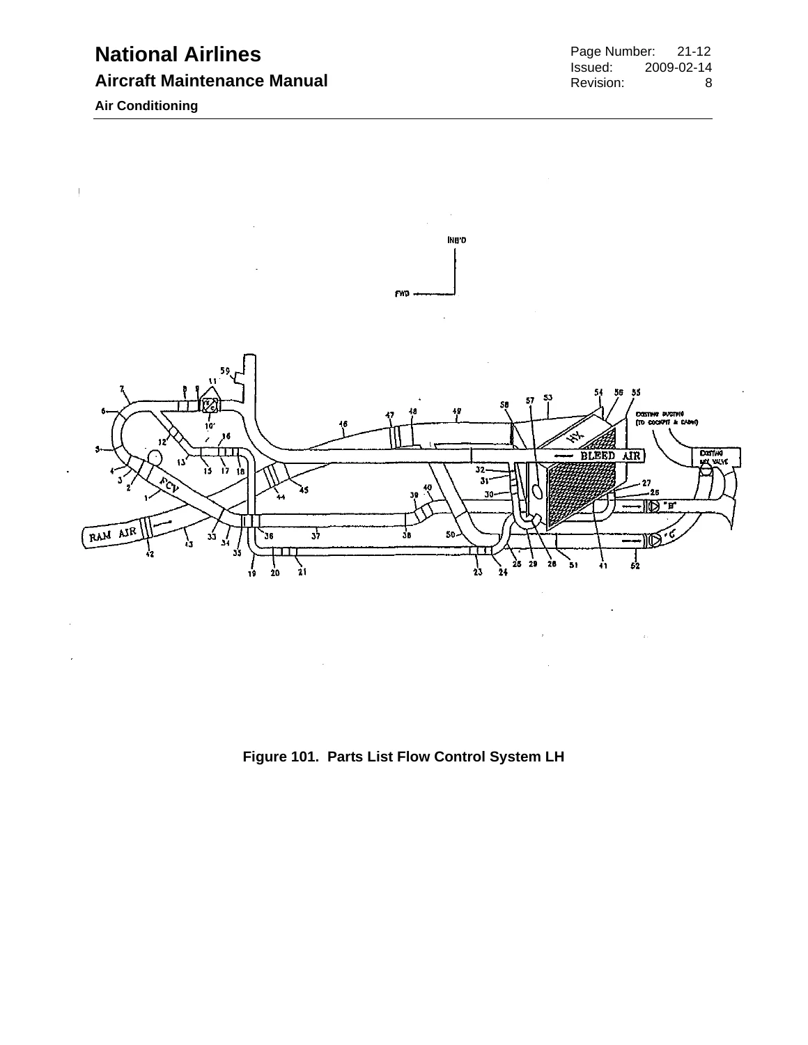
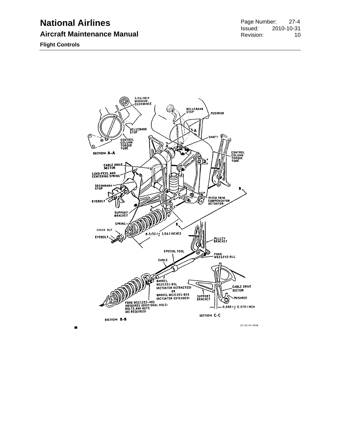
Reviews
There are no reviews yet.