
New Holland 70 Series 70A Series Tractor Service Repair Manual – 8670 8770 8870 8970 PDF
Original price was: $104.95.$69.95Current price is: $69.95.
Complete New Holland 70/70A Series tractor service repair manual covering 8670, 8770, 8870 and 8970 models. Engine, transmission, hydraulics, electrical, cab and bodywork – instant PDF download.
Description
New Holland 70 & 70A Series Tractor Service Repair Manual – 8670, 8770, 8870, 8970
This is the complete New Holland 70 Series and 70A Series Tractor Service Repair Manual, covering the 8670, 8670A, 8770, 8770A, 8870, 8870A, 8970 and 8970A models. It is the same comprehensive workshop manual used by professional technicians for everything from routine maintenance to full engine overhauls, transmission disassembly, hydraulic diagnostics, electrical fault-finding and cab removal. Every major system on these tractors is documented in detail, with clear procedures, exploded illustrations, wiring and hydraulic schematics, torque values and specification tables throughout.
Whether you are servicing your own 8670, repairing a customer’s 8970A, or maintaining a fleet of 70 Series tractors, this New Holland service manual gives you the correct procedures, the right specs, and the detailed diagrams needed to get the job done properly. It covers the entire machine – from the engine and fuel system through the powershift transmission, drive lines, front and rear axles, PTO, brakes, steering, hydraulic system, climate control, electrical system, and the complete cab and bodywork.
File Details
- Manual Type: Service Repair Manual
- Brand: New Holland
- Series: 70 Series / 70A Series
- Models Covered: 8670, 8670A, 8770, 8770A, 8870, 8870A, 8970, 8970A
- Engine: 7.5 L (456 cu in), 6-cylinder turbocharged
- Language: English
- Format: PDF
- Pages: 2,000+
Chapters Covered
- Section 00 – General Information
- Section 10 – Engine (Lubrication, Cooling, Induction, Fuel System, Engine Removal, Fuel Tank)
- Section 21 – Transmission (Operation and Overview, Separating Engine and Front Axle, Separating Rear Axle, Mechanical System, Hydraulic System, Electrical System)
- Section 23 – Drive Lines (Four-Wheel Drive Clutch)
- Section 25 – Front Mechanical Drive (Dana Axle, SuperSteer Linkage, Carraro Axle)
- Section 27 – Rear Drive Axle
- Section 31 – Power Take-Off (Mechanical System, Electro-hydraulic System)
- Section 33 – Brakes and Controls (Power Brakes, Parking Brake, Trailer Air Brakes, Trailer Air Brake Electrical System)
- Section 35 – Hydraulic Systems (Introduction, Low-Pressure System, Tandem Gear Pump, Axial Piston Pump, Flow Divider, 70 Series Remote Valves, 70A Series Electro-Hydraulic Remote Valves, Remote Valve Couplers, Remote Valve Removal and Repair, Three-Point Hitch, Power-Beyond Applicators, Hydraulic Brake System, Pressure and Flow Testing, EHR Calibration and Diagnostics)
- Section 41 – Steering (Hydrostatic Steering)
- Section 44 – Two-Wheel Drive Axle and Wheels (Front Axle, FWD Track Spacing, Rear Wheel Track Spacing, Rear Wheel Removal/Replacement)
- Section 50 – Climate Control
- Section 55 – Electrical Systems (EIC and System Overview, Fault Codes and Diagnostics, Starting System, Charging System, Lighting Auxiliary Power and Radios, Wiring Diagrams, Electro-Hydraulic Remote Valve Control System)
- Section 90 – Platform, Cab and Bodywork (Cab Components, Engine Hood Removal, Cab Removal)
Section 00 – General Information
Opens with the foreword, precautionary statements, and comprehensive safety precautions covering personal protection (skin, eye, breathing, hearing, lifting, hand and foot protection) and equipment considerations. Tractor identification data is detailed with locations for the vehicle identification plate, engine identification, fuel injection pump identification, starter motor identification, transmission identification, tandem gear pump identification, axial piston pump identification, rear axle identification, and cab identification. Also includes service techniques, sealer specifications, hardware torque values, and recommended lubricants and coolants for North America and Europe.
Section 10 – Engine
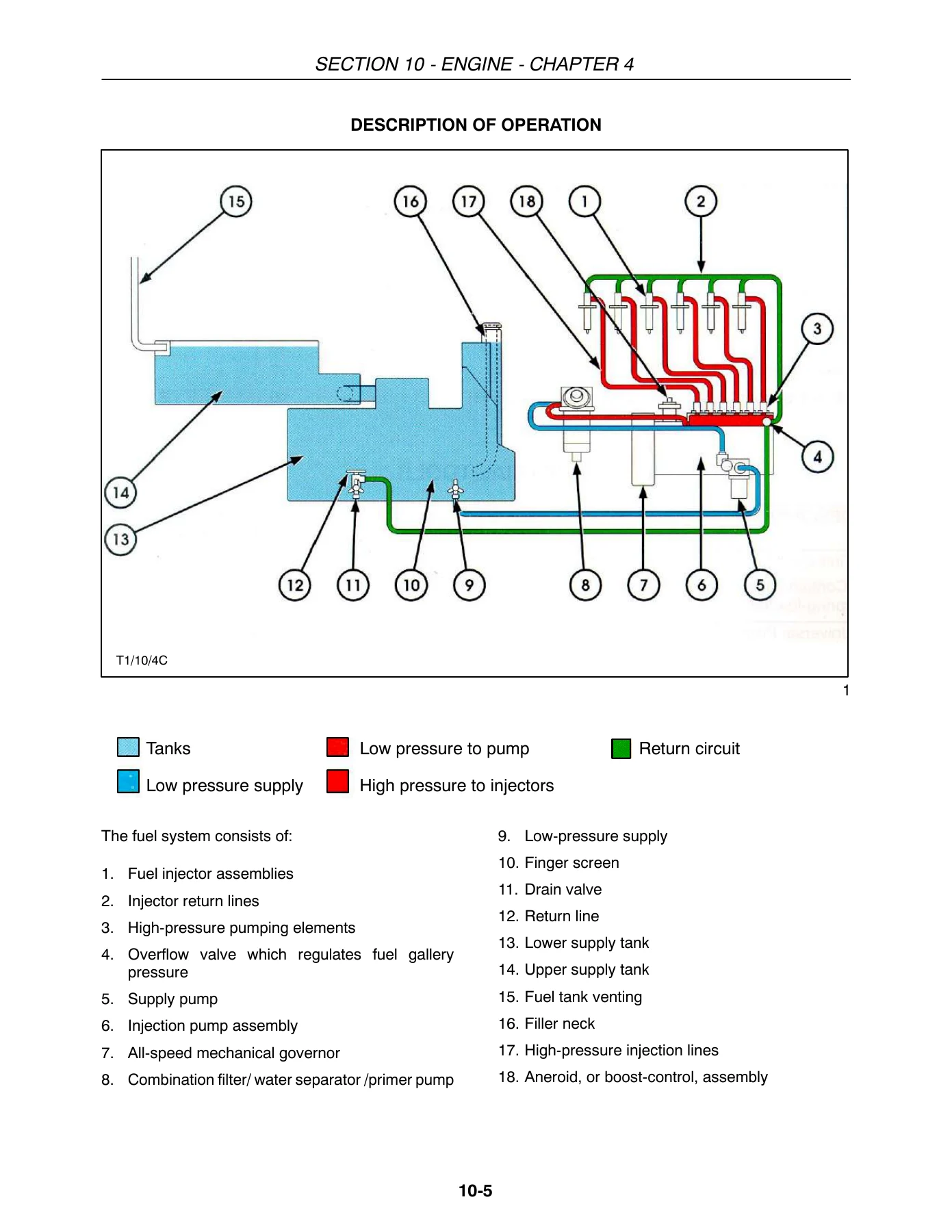
Covers the complete engine assembly including cylinder head, camshaft, crankshaft, connecting rods, pistons, manifolds, cylinder block, timing gears, and engine lubrication. Includes detailed specifications, torque values, and step-by-step procedures for cylinder head removal and reassembly, crankcase front cassette seal, oil pan, connecting rods, bearings, pistons and rings, cylinder block overhaul, main bearings, flywheel, crankshaft, camshaft, and engine timing gears. Also includes an engine compression test procedure, cooling system specifications and troubleshooting, radiator, thermostat, water pump, fan blade, viscous clutch, fan belt tensioner and idler pulley procedures. The induction system chapter covers the air cleaner, turbocharger and intercooler with troubleshooting and overhaul procedures. The fuel system chapter provides complete coverage of the fuel tank, low-pressure and high-pressure fuel systems, fuel tank valves, filter inlet and outlet pressure tests, injection timing check, fuel injector nozzle check, injector assembly bench testing, surging diagnosis, fuel shutoff diagnosis, bleeding the fuel system, throttle cable adjustment, high idle and low idle adjustment, fuel lift pump, fuel shutoff solenoid, fuel injection pump, fuel injection lines, injector leak-off line, fuel filter, and injection nozzles. Engine removal and fuel tank removal procedures are also included.
Section 21 – Transmission
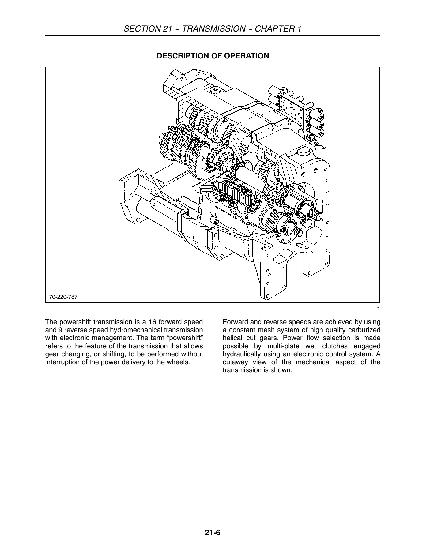
Provides complete coverage of the 16×9 powershift transmission with specifications, gear ratios, ground speed charts for 8670/8670A and 8770/8770A/8870/8870A/8970/8970A with 18.4-42 tires, electrical system component locations and functions, transmission housing, powershift transmission controls, digital display, inching pedal, starting and moving forward, starting and moving in reverse, shuttle operations, speed matching, auto shift, creeper gears, programmable upshift/downshift, transmission components, clutches, speed clutches, directional clutches, clutch engagement, and troubleshooting. Separating the engine and front axle from the transmission and separating the rear axle from the transmission are covered in dedicated chapters, along with the mechanical system including rear housing and directional clutch removal, front housing and speed clutch removal, main input gear assembly removal, speed clutch disassembly and inspection, directional clutch disassembly and inspection, reassembly, transmission shimming, and creeper gear repair. The hydraulic system chapter covers the low-pressure hydraulic system, regulator valve operation, clutch valve operation, modulator valve operation, electro-hydraulic pilot line, troubleshooting and diagnosis, transmission test sheet, electrical/electronic system checks, hydraulic system checks, clutch apply pressure chart, pressure testing and adjustments, clutch apply circuit pressure testing, transmission pressure checklist, transmission programming, programmable upshift/downshift, reverse gear ratio programming, transmission calibration, calibration review, calibrating F1, F2, and reverse directional clutches, exit calibration mode, calibration of shift constant, removal and disassembly of the complete valve assembly, disassembly, solenoid and valve assembly, speed and directional clutch circuit valves, modulator valves, regulator valve, lubrication and cooling circuit relief valve, inspection, reassembly, and installation. The electrical system chapter covers the clutch apply circuits, modulation solenoids, shift control lever, inching pedal, speed sensors, display module, troubleshooting and diagnosis, transmission solenoid and pressure testing, control valve solenoids, chassis control module, inching pedal switches, transmission shift control, shift control circuit board assembly, shift control assembly, handle disassembly, neutral latch adjustment, shifter pivot assembly, and installing the shift control assembly.
Section 23 – Drive Lines
Covers the four-wheel drive clutch with description of operation for 70 Series FWD electronic control, 70A Series FWD electronic control, engaging and disengaging four-wheel drive, FWD operating precautions, removal, disassembly, inspection, reassembly, installation, and pressure testing.
Section 25 – Front Mechanical Drive
Provides complete coverage of the Dana front axle including specifications, special tools, description of operation, troubleshooting, wheel toe-in adjustment, FWD steering stop adjustment, hub bearing preload adjustment, checking for correct pinion to ring gear tooth contact, wrong tooth contact pattern diagnosis, swivel pin bearing adjustment, FWD ratios, FWD tire vs gear ratios, four-wheel drive lead factor, front axle serviceability, lubrication, disassembly and repair including front axle, steering cylinders, planetary reduction, hub, swivel housing, center housing swivel bearing, drive shaft, outer yoke, differential, and crown wheel to backlash adjustment. Also covers the Dana SuperSteer linkage with description of operation, supersteer linkage removal, removal of rear support assembly and spherical ball bushing, and supersteer linkage adjustment. The Carraro axle chapter covers specifications, special tools, general information, front axle differential line, overall dimensions, general checks prior to disassembly, disassembly operations, front axle removal and installation, steering cylinders group disassembly and assembly, final drive removal, wheel hub disassembly and assembly, swivel housing removal and assembly, axle housing swivel bearing, differential support group disassembly and assembly, input flange end play adjustment, limited slip differential removal, limited slip pinion disassembly, limited slip differential disassembly and assembly, lockable differential removal, lockable pinion disassembly, lockable differential disassembly and assembly, adjustment of pinion shaft, differential adjustments, pinion to ring gear tooth contact adjustment, wrong tooth contact pattern, swivel housing bearing adjustment, standard steer/toe-in adjustment, supersteer linkage adjustment, potentiometer removal, installation, and calibration, Mode 12 tractor features configuration, Mode 13 steering angle sensor operation/calibration, new parameter code, new fault codes, testing after assembly, and troubleshooting.
Section 27 – Rear Drive Axle
Covers the rear axle assembly with specifications, special tools including dealer constructed special tools, description of operation, differential carrier, final reduction drive, differential lock mechanical operation, 70 Series differential lock control system operation, 70A Series differential lock control system operation, differential lock electrical circuit operation, differential lock hydraulic circuit operation, front axle differential line for 70A Series, troubleshooting for differential lock will not engage and will not disengage with electrical and hydraulic troubleshooting charts, adjustments including axle shaft bearing preload adjustment, pinion depth adjustment, pinion bearing preload adjustment, differential support bearings preload adjustment, ring and pinion gear backlash adjustment, and ring and pinion gear tooth contact pattern check and adjustment. Disassembly and repair includes axle assembly removal and installation, axle housing assembly overhaul for 8670/8670A and 8770/8770A/8870/8870A/8970/8970A, planetary overhaul, axle seal, top cover removal and installation, differential and differential lock assembly overhaul, pinion assembly overhaul, differential lock solenoid, pressure testing, and circuit pressure test.
Section 31 – Power Take-Off
Covers the mechanical system with specifications, special tools, description of operation, power flow for all models, engaging and disengaging the PTO, troubleshooting and diagnosis, PTO assembly removal and installation, upper PTO input shaft removal and installation, PTO output shaft and driven gear overhaul for 8670/8670A and 8770/8770A/8870/8870A/8970/8970A, and PTO clutch assembly overhaul. The electro-hydraulic system chapter covers specifications, special tools, description of operation, engaging and disengaging the PTO, PTO hydraulic system operation, PTO control valve operation including PTO disengaged mode, PTO feathering mode, PTO engaged mode, lubrication oil, PTO electrical system operation including PTO off circuit, PTO start-up circuit, PTO running circuit, PTO shutdown circuit, troubleshooting for PTO will not engage, PTO will not disengage, PTO clutch slips under load, PTO shaft continually turns slowly with engine running when PTO is turned off, PTO retaining ring is difficult to replace, adjustments for PTO clutch brake band, PTO solenoid, PTO control valve assembly, PTO system pressure testing, pilot oil circuit pressure test, clutch apply circuit pressure test, and PTO lubrication circuit pressure test.
Section 33 – Brakes and Controls
Covers power brakes with specifications, description of operation, boosters, master cylinders, rear axle brake assemblies, four wheel braking, troubleshooting, adjustments including bleeding the brakes, brake pedal adjustment, brake switch adjustment, power brake valve overhaul, inspection, reassembly, installation of the brake lube kit, and rear axle brakes overhaul. The parking brake chapter covers specifications, special tools, description of operation, adjustments, troubleshooting, and parking brake overhaul. Trailer air brakes chapter covers specifications, torque specifications, safety, general air brake safety, general maintenance instructions, description of operation, system operation, air compressor, unloader valve, reservoir tank, right hand brake lamp switch, solenoid valve, dual control valve, single control valve, air pressure switch, trailer brake solenoid power, disassembly and repair of air compressor, air compressor lubrication supply line, air compressor lubrication return line, air pressure supply line, unloader valve/silencer, reservoir, pressure switch, single control valve, dual control valve, solenoid control valve, coupler connectors, adjustments, system testing, troubleshooting, towed vehicle, and towed vehicle troubleshooting. Trailer air brake electrical system chapter covers description of operation, trailer brake light, low pressure alarm, air pressure switch power, harness removal and installation, cab trailer wiring harness, rear trailer harness, and troubleshooting.
Section 35 – Hydraulic Systems
Provides the most extensive coverage of any section. The introduction covers specifications, description of operation, closed center load sensing (CCLS) pump and remote valve system, standard flow hydraulic system, MegaFlow hydraulic system, variable displacement pump, priority flow divider, remote control valves for standard flow tractors and MegaFlow tractors, and low-pressure return circuit. The low-pressure system chapter covers specifications, description of operation, hydraulic pump drive assembly, tandem gear pump assembly, tandem gear pump fluid supply, oil filters, oil reservoir, oil cooler and bypass valve, low-pressure control hydraulic schematic, removal and disassembly, hydraulic pump inlet screen, charge pressure regulator valve, filters, filter head, cooler bypass valve, hydraulic oil cooler, accumulator, hydraulic pump drive gear case, and repairing the pump drive gear case bearings. The tandem gear pump chapter covers specifications, special tools, description of operation, operation, disassembly and repair, removal, disassembly, inspection of parts, assembly, performance testing, and installation. The axial piston pump chapter covers specifications, special tools, description of operation, pressure control valve, variable displacement pump, operation including tractor not running, low pressure standby, pump going into stroke, pressure flow compensation, high-pressure standby, removal, tools required, disassembly, input shaft seal replacement, seal installation, compensator valve disassembly, main pump disassembly, swash plate removal, input shaft, pump reassembly, rotating group assembly, flow and pressure compensator valves, and pump installation. The flow divider chapter covers specifications, description of operation, priority flow divider, disassembly and repair, removal, teardown, and assembly. The 70 Series remote valves chapter covers specifications, special tools, description of operation, remote valve assembly, remote valve section for series logic and parallel logic, control cables, return tube, primary and secondary shuttles, order of priority operation. The 70A Series electro-hydraulic remote valves chapter covers specifications, electro hydraulic remote valves, control switches, flow control adjustment, description of operation, flow control operation, and order of priority operation. The remote valve couplers chapter covers specifications, coupler mounting block and coupler repair for 70 Series before and after serial number D408953. The remote valve removal and repair chapter covers removal, remote valve removal, removing individual valve assemblies, valve reassembly, teardown and reassembly, individual valve section disassembly, valve section overhaul for 70 Series, detent release overhaul for 70 Series, valve section overhaul for 70A Series. The three-point hitch chapter covers specifications, description of operation, three-point hitch, three-point hitch external linkage components, quick hitch, troubleshooting including three-point hitch will not raise, will not lower, electronic draft control will not function, slip control will not operate, disassembly and repair, rockshaft removal, seal and bushing replacement, rockshaft installation, and lift cylinder removal. The power-beyond applicators chapter covers special tools and power-beyond applications. The hydraulic brake system chapter covers closed center load sensing hydraulic brake system, operation of the European trailer brake system, operation of the 10 bar trailer brake system for Italian market only, trailer brake valve pilot head operation, trailer brake valve operation, trailer brake valve specifications, torques, special tools, description, trailer brake valve removal, disassembly, inspection and repair, re-assembly and installation, bleeding the brakes, bleeding rear axle brakes, trailer brake valve bleed screws, and trailer brake pressure test. The pressure and flow testing chapter covers specifications, special tools, description of operation, low-pressure system testing, testing low-pressure system, high-pressure system testing, axial piston pump, steering flow divider relief pressure, steering flow divider flow test, remote valve, detent release operation, timed detent release operation, three-point hitch, and three-point hitch and remote valve troubleshooting aid tool. The EHR calibration, diagnostics and hydraulic system troubleshooting chapter covers calibration of the electro-hydraulic control system, functions of the PDT, set up, start calibration, set defaults, deadband, calibration of the pod levers, set currents, setting the flow control potentiometer, changing the lever deadband, diagnostics of the electro-hydraulic remote valve control system, solenoid errors, lever errors, system errors, other screens, troubleshooting electro-hydraulic self test, troubleshooting hydraulic system, and hydraulic system quick checks.
Section 41 – Steering
Covers hydrostatic steering with specifications, minimum hardware tightening torques, description of operation, steering system control valve, steering control valve types, steering cylinders, troubleshooting, removal and disassembly, steering control valve, parts inspection, assembling the steering control unit, and installing the steering control valve.
Section 44 – Two-Wheel Drive Axle and Wheels
Covers the two-wheel drive front axle with specifications, special tools, description of operation, troubleshooting, adjustments including front wheel track spacing, 2WD axle adjustment, front wheel position, front wheel toe-in, disassembly and repair, axle removal, axle installation, axle center beam bushing replacement, axle extension installation, spindle removal and disassembly, axle extension/spindle bushing replacement, spindle reassembly, front wheel bearing, steering cylinder, center steering arm, and steering rod. The FWD front axle track spacing chapter covers specifications, four wheel drive front axle track spacing, four wheel drive track adjustment, and front wheel positions. The rear wheel track spacing chapter covers specifications, special tools, rear wheel track spacing, introduction, Model 8670/8670A tractors, Model 8770/8770A, 8870/8870A and 8970/8970A tractors, rear wheel track adjustment, adjusting rear wheels, and dual rear wheels. The rear wheel removal/replacement chapter covers specifications, special tools, description of operation, removal, and installation.
Section 50 – Climate Control
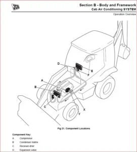
Covers the climate control system with introduction, specifications, tightening torques, description of operation, controls, air conditioning process, air conditioning system components, compressor, compressor operation, condenser, receiver/drier, sight glass, expansion valve, expansion valve operation, evaporator coil, heater core, air conditioning electrical controls, blower fan, air filtration, air-conditioner thermostatic control switch, blower motor resistor, relay switch, high/low-pressure cutout switch, water valve, engine coolant shutoff valves, lubricants, refrigerant R-134a, troubleshooting and servicing air conditioning system, general safety and service precautions, cleanliness, primary troubleshooting and testing, diagnosis chart, test procedure for stabilizing the system, check for leaks first, refilling, contaminants, prevent mixing of service equipment, refrigerant recovery and recycling equipment, using recovery equipment, using recycling equipment, recycled versus reclaiming, refrigerant recovery procedure, flushing, recharge/refilling, use of a manifold gauge set, checking refrigerant for excess air, containers for the storage of recycled refrigerant, transfer of refrigerant, disposal of empty or near empty disposable containers, applicable SAE standards, A/C system performance test and diagnosis chart, manifold gauge readings and interpretations, and component removal and installation.
Section 55 – Electrical Systems
Covers the electronic instrument cluster (EIC) and system overview with specifications, description of operation, main distribution panel, service diagnostics, electronic instrument cluster, central LCDs, tractor performance monitor, automatic engine shutdown, 70 Series indicator warning lamps and audible alarm, 70A Series indicator warning lamps and audible alarm, air filter restriction, differential lock, cold start assist (ether), cold start assist (air inlet), coolant level low, alternator charge indicator, intercooler overheated, transmission pressure low, transmission rear axle/hydraulic oil temperature, hydraulic/transmission filters restricted, PTO engaged, programmable up shift, programmable down shift, 70 Series FWD on, FWD auto, 70A Series FWD on, four wheel drive (FWD) switch, headlight high beam, system status, parking brake, bar graph displays, stop and audible alarm conditions, central display, lower selectable display, electronic instrument cluster tractor performance monitor, automatic display information, selectable display information, EIC lighting display, troubleshooting and diagnostics, EIC harness tool, Mode 1 operator calibrations, Mode 2 view stored fault codes, Mode 3 all module input parameters, Mode 4 EIC output diagnostics, Mode 5 RHC output diagnostics, Mode 6 EDC output diagnostics, Mode 7 ETC output diagnostics, Mode 8 EIC full display test, Mode 9 hardware/software revision level, Mode 10 transmission calibration review and programming, Mode 11 3-point hitch and EDC calibration, Mode 12 tractor features configuration, and Mode 13 steering angle sensor operation/calibration for 70A Series. The fault codes and diagnostics chapter covers description of operation, 70/70A Series diagnostics procedure overview and checklist, system grounds, 70 Series electrical system grounds, troubleshooting checklist, special tool for testing electrical systems, electrical test procedures including continuity test for short to ground, voltage measurement or short to positive supply volts, resistance test for electrical parts, continuity test for open circuits, fault codes F001 to F099 for 3-point hitch/EDC, fault codes F100 to F199 for right-hand controls, fault codes F200 to F299 for EIC module, fault codes F300 to F399 for ETC transmission control, and fault codes F400 to F499 for engine control. The starting system chapter covers specifications, description of operation, batteries, cold start system ether operation, ether cold start circuit troubleshooting, cold start system air inlet heater, air inlet heater troubleshooting, fuel stop solenoid and override system, shutdown override, troubleshooting the cranking circuit, disassembly and repair, cleaning, armature servicing, field coil checks, field coil removal, solenoid checks, three-terminal solenoid, reassembly, lubrication, and pinion clearance. The charging system chapter covers specifications, torque specifications, description of operation, features, operating principles, troubleshooting and diagnosis, disassembly and repair, unit repair, disassembly and bench checks, and generator assembly. The lighting, auxiliary power and radios chapter covers specifications, description of operation, controls, multi-function switch, hazard warning lights, light operation, work lights, auxiliary power, auxiliary control mounting locations, auxiliary control cable routing, radio installation, troubleshooting, fuse and relay identification, circuit diagrams, brake lights, head lights, hazard warning lights, 70 Series turn signals, 70A Series turn signals, taillights, work lights, work lights #1, #2, #3, #4, interior lights, auxiliary power sockets, 70 Series seven-pin trailer connector, 70A Series seven-pin trailer connector, disassembly and repair, replace headlight assembly bulbs, replace work sealed beam units, replace roof mounted turn signal bulbs, replace the fender mounted turn signal and stop light/parking light bulbs, electronic instrument cluster bulb replacement, harness repair, connector repair and replacement, and main harness routing. The wiring diagrams chapter covers description of operation, harness and connectors, wiring diagram index and key, wiring diagram circuit explanation, glossary of terms/abbreviations, component index, NASO schematic, and ISO schematic. The electro-hydraulic remote valve control system chapter covers system description, electrical operation, electro-hydraulic remote valve switch control pod locations, the switch control pod components, remote valve solenoid connections, programmable controller location, switch valve color-coding, electro-hydraulic control switch function positions, electro-hydraulic flow control knob, manual programmable operation switch, electro-hydraulic remote valve engagement switch, fuse panel location, fuse panel access, fuse location, control relays, main fuse panel location, main fuse panel access, main fuses, manual operation, programmable mode, flow control, EHR electrical test procedures, continuity test for short to ground, continuity test for open circuits, voltage measurement or short to positive supply volts, EHR system has no power, removal of the electro-hydraulic remote control valve switch pod assembly, reassembly, removal of the electro-hydraulic remote control valve programmable controller, and installation of the electro-hydraulic remote control valve programmable controller.
Section 90 – Platform, Cab and Bodywork
Covers cab components with description, disassembly and assembly, headliner, cab trim, seat, door removal, rear window, instrument cluster, steering column, right-hand console, and procedures for right-hand console upgrade. Engine hood removal chapter covers specifications, description of operation, disassembly and repair, hood removal, and hood and upper engine frame removal. Cab removal chapter covers specifications, special tools, description of operation, disassembly and repair, cab removal, and cab installation.
Who This New Holland 70 Series Service Manual Is For
This New Holland 70 and 70A Series tractor service manual is essential for anyone responsible for the maintenance, repair or overhaul of 8670, 8670A, 8770, 8770A, 8870, 8870A, 8970 or 8970A tractors. That includes professional agricultural mechanics, fleet maintenance technicians, farm owners who service their own equipment, and equipment dealers who need factory-level procedures and specifications. Because these tractors are widely used in heavy tillage, planting, harvesting and transport operations, having the correct service information on hand is the difference between a quick, correct repair and a costly comeback.
What This New Holland 70 Series Repair Manual Enables You To Do
With this manual, you can confidently perform engine overhauls – including cylinder head removal, valve seat replacement, piston and ring installation, and crankshaft and main bearing service. You can diagnose and repair the powershift transmission, including clutch pack replacement, hydraulic control valve service, and electronic calibration. You can separate the tractor at the engine/transmission or transmission/rear axle connections and complete major internal repairs. The drive lines, front and rear axles, PTO clutch, brakes, steering system, hydraulic pumps and valves, climate control system, and the full electrical system with fault code diagnostics are all covered in step-by-step detail.
The New Holland 70 Series service manual also provides the torque values, clearances, pressure specifications, and diagnostic procedures you need to verify every repair. Whether you are troubleshooting a transmission pressure lamp, calibrating the three-point hitch, setting up the differential lock, or bleeding the brakes after a major service, the correct specs are here.
Why Correct Procedures and Specifications Matter
Modern agricultural tractors like the New Holland 8670, 8770, 8870 and 8970 are complex machines. The powershift transmission uses electrohydraulic control, the engine relies on precise fuel injection timing, and the hydraulic system operates at pressures up to 200 bar (2900 PSI) on 70A Series models. Using the wrong torque value, missing a critical adjustment, or skipping a calibration step can lead to premature failure, expensive component damage, or unsafe operating conditions. This manual gives you the exact procedures and specifications that New Holland engineers published for these tractors, so you can work with confidence.
IMAGES PREVIEW
Instant PDF Download – No Shipping, No Waiting
This New Holland 70/70A Series Tractor Service Repair Manual is delivered as an instant PDF download. There is no physical book to ship, no waiting for delivery, and no risk of a lost or damaged manual. After purchase, you can download the file immediately and access it on any device – laptop, desktop, tablet or smartphone. The PDF can be printed in full or in sections, so you can take the pages you need to the shop or the field. Whether you are working on an 8670 in the barn or an 8970A at a remote job site, this manual puts the complete service information at your fingertips.
Reviews
There are no reviews yet.