New Holland Crawler Excavator E16B E18B Service Repair Manual 87743534 – PDF DOWNLOAD
Original price was: $78.95.$28.95Current price is: $28.95.
New Holland Crawler Excavator E16B E18B Service Repair Manual 87743534
Description
New Holland Crawler Excavator E16B E18B Service Repair Manual 87743534
FILE DETAILS:
New Holland Crawler Excavator E16B E18B Service Repair Manual 87743534
Language : English
Pages : 614
Downloadable : YES
Format : PDF
Size : 37.6 MB
Print No. 87743534
DESCRIPTION:
New Holland Crawler Excavator E16B E18B Service Repair Manual 87743534
SAFETY INSTRUCTION:
The operator or serviceman may be unfamiliar with many of the systems in this machine. This makes a careful use of the systems very important when performing maintenance operations. Getting familiar with the system or its components is very important before removing or disassembling any of them. Because of the size of some of the machine’s components, the operator or serviceman should check the weights noted in this manual. Use proper lifting procedures when removing any components. The following is a list of basic precautions that must always be observed.
- Read and understand all warning labels and safety decals before operating, servicing or repairing this machine. Always wear protective glasses and protective shoes when working around machines. In particular, wear safety goggles when using hammers, punches or drifts on any part or attachment of the machine.
- Use gloves, safety goggles, aprons and protective clothing appropriate for welding jobs. Do not wear loose accessories or torn clothes. Remove all rings from fingers, loose jewellery, confine long hair and loose clothing before working on this machine. Disconnect the battery and hang a “Maintenance in progress” tag in the operator’s compartment. Remove the starter switch key. If possible, make all repairs with the machine parked on a level and firm surface.
- Block the machine so it does not roll while working on or under the machine. Hang a “Maintenance in progress” tag in the operator’s compartment. Do not work on any machine that is supported only by lift, jacks or a hoist. Always use blocks or stops for the jack before carrying out any disassembly operation. Relieve all pressure in air, oil or fuel systems before any lines, fittings or related devices are disconnected or removed. Always make sure that all raised components are blocked correctly and pay attention to possible pressures when disconnecting any device from a system under pressure.
- Lower the bucket, dozer or other attachments to the ground before performing any operation on the machine. If this cannot be done, make sure the bucket, dozer or other attachment is blocked correctly to prevent it from dropping unexpectedly. Use the steps and the grab handles when mounting or dismounting the machine. Remove any debris or mud from steps, walkways or work platforms before using them. Always face the machine when using steps, ladders and walkways.
- When it is not possible to use the designed access system, provide ladders, scaffolds, or work, platforms to perform safe repair operations. To prevent back injury, use a hoist when lifting components which weigh 20 kg (45 lbs) or more. Make sure all chains, hooks, slings, etc., are in good condition and have the correct capacity. Be sure hooks are positioned correctly. Lifting eyes are not to be side loaded during a lifting operation. In order to prevent burns, be careful not to touch hot machine parts and hot liquids in systems.
- Be careful when removing cover plates. Gradually back off the last two screws or nuts located at opposite ends of the cover or device and carefully pry the cover loose to relieve any spring or other pressure before removing the last two screws or nuts completely.
- Be careful when removing filler caps, breathers and plugs on the machine. Hold a rag over the cap or plug to prevent being sprayed or splashed by liquids under pressure. Danger is even greater if the machine has just been stopped, as liquids might be boiling hot. Always use proper tools that are in good condition and that are suited for the job at hand. Be sure you understand how to use them before performing any service work. Replace all clamps with original spare parts. Do not use clamps of a lesser quality.
TABLE OF CONTENTS:
New Holland Crawler Excavator E16B E18B Service Repair Manual 87743534
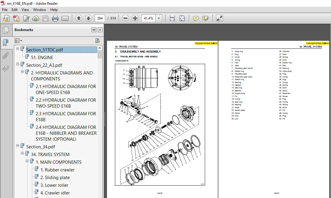
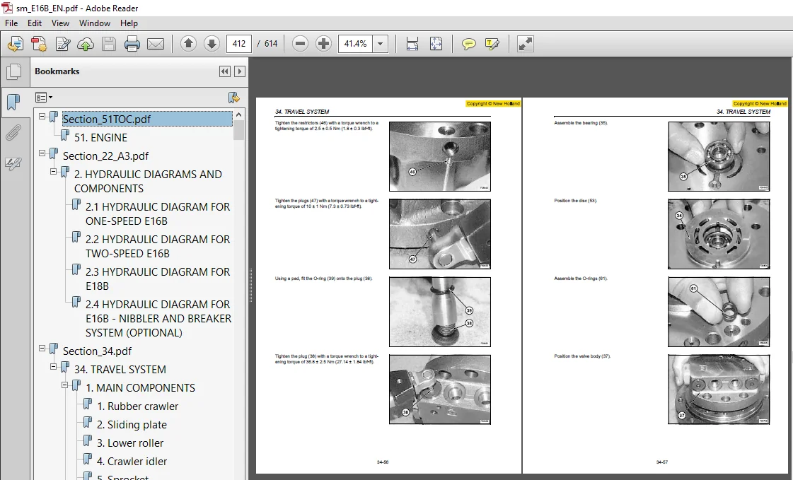
Section_51TOC.pdf...................................................................................................................................................................................................  0
	51. ENGINE......................................................................................................................................................................................................461
Section_22_A3.pdf...................................................................................................................................................................................................  0
	2. HYDRAULIC DIAGRAMS AND COMPONENTS............................................................................................................................................................................111
		2.1 HYDRAULIC DIAGRAM FOR ONE-SPEED E16B....................................................................................................................................................................111
		2.2 HYDRAULIC DIAGRAM FOR TWO-SPEED E16B....................................................................................................................................................................113
		2.3 HYDRAULIC DIAGRAM FOR E18B..............................................................................................................................................................................115
		2.4 HYDRAULIC DIAGRAM FOR E16B - NIBBLER AND BREAKER SYSTEM (OPTIONAL)......................................................................................................................................117
Section_34.pdf......................................................................................................................................................................................................  0
	34. TRAVEL SYSTEM...............................................................................................................................................................................................357
		1. MAIN COMPONENTS..........................................................................................................................................................................................359
			1. Rubber crawler.......................................................................................................................................................................................359
			2. Sliding plate........................................................................................................................................................................................359
			3. Lower roller.........................................................................................................................................................................................359
			4. Crawler idler........................................................................................................................................................................................359
			5. Sprocket.............................................................................................................................................................................................359
			6. Travel motor.........................................................................................................................................................................................359
			7. Slewing bearing......................................................................................................................................................................................359
			8. Track width enlargement device.......................................................................................................................................................................359
		2. REMOVAL AND INSTALLATION.................................................................................................................................................................................360
			2.1 RUBBER CRAWLER......................................................................................................................................................................................360
				Tension value (A):..................................................................................................................................................................................361
					If the machine is operated with a loose rubber crawler, there is the risk that the crawler springs and wears prematurely........................................................................361
				Rib height..........................................................................................................................................................................................361
				Crack of rubber shoe................................................................................................................................................................................361
				Metal core detachment...............................................................................................................................................................................362
					The metal core can easily detach if the rubber crawler is not used correctly....................................................................................................................362
			2.2 SLIDING PLATE.......................................................................................................................................................................................363
				Slowly rotate the grease cup, paying attention not to rotate it by more than one turn. Prevent grease from spattering...............................................................................363
			2.3 LOWER ROLLER........................................................................................................................................................................................364
				1. Seal ring........................................................................................................................................................................................364
				2. Roller body......................................................................................................................................................................................364
				3. Plug.............................................................................................................................................................................................364
				4. Shaft............................................................................................................................................................................................364
				5. Bearing..........................................................................................................................................................................................364
				6. Elastic ring.....................................................................................................................................................................................364
				7. Collar...........................................................................................................................................................................................364
				8. Washer...........................................................................................................................................................................................364
				9. Screw............................................................................................................................................................................................364
					- Replace the seal ring with a new one during assembly..........................................................................................................................................367
					- If the seal ring is incorrectly installed because of an uneven pressure, it could get damaged quickly and not guarantee sealing...............................................................367
					- After assembling the roller, manually check for smooth rotation and make sure that there are no leaks.........................................................................................367
			2.4 CRAWLER IDLER.......................................................................................................................................................................................368
				B. Idler assy.......................................................................................................................................................................................368
				1. Screw............................................................................................................................................................................................368
				2. Wheel............................................................................................................................................................................................368
				3. Shaft............................................................................................................................................................................................368
				4. Bracket..........................................................................................................................................................................................368
				5. Bearing..........................................................................................................................................................................................368
				6. Elastic ring.....................................................................................................................................................................................368
				7. Seal ring........................................................................................................................................................................................368
				8. Plug.............................................................................................................................................................................................368
				9. Piston...........................................................................................................................................................................................368
				10. Seal ring.......................................................................................................................................................................................368
				11. O-ring..........................................................................................................................................................................................368
				12. Cylinder........................................................................................................................................................................................368
				13. Spring..........................................................................................................................................................................................368
				14. Plate...........................................................................................................................................................................................368
				15. Nut.............................................................................................................................................................................................368
				16. Split pin.......................................................................................................................................................................................368
				17. Pin.............................................................................................................................................................................................368
				18. Valve...........................................................................................................................................................................................368
				19. Disc............................................................................................................................................................................................368
				- Crawler idler weight: 22 kg (48 lb)...............................................................................................................................................................369
				- loosen and remove the screws (4);.................................................................................................................................................................369
				- remove the free wheel (3) complete with the two side supports (5).................................................................................................................................369
				free wheel weight: 16 kg (35 lb)....................................................................................................................................................................369
				idler weight: 6 kg (13 lb)..........................................................................................................................................................................369
				Reassemble the free wheel and the idler. Tightening torque of screws (4): 33 Nm (24.33 lbf.ft)......................................................................................................369
				Install the crawler idler assy by inserting it between the plates of the lower frame. Pay attention that the idler valve remains oriented upwards...................................................369
				Assemble the rubber crawler.........................................................................................................................................................................369
				Adjust the crawler and the crawler idler tension....................................................................................................................................................369
				If bearing (5) replacement is not necessary, do not remove it from the shaft (3)....................................................................................................................370
				In case the bearing is reused, check that its rotation is correct and that it does not show defects or rust.........................................................................................370
				Apply some grease to the wheel (2), press-fit the shaft (3) along with the bearing (5) into the crawler idler.......................................................................................370
				Install the elastic ring (6)........................................................................................................................................................................370
					- Replace the seal ring with a new one during reassembly........................................................................................................................................370
					- If the seal ring is incorrectly installed because of an uneven pressure, it could get damaged quickly and not guarantee sealing...............................................................370
				Following the same procedure, assemble the seal ring (7) on the opposite side.......................................................................................................................370
				Idler disassembly...................................................................................................................................................................................371
				A. Support base.....................................................................................................................................................................................371
				B. Base.............................................................................................................................................................................................371
				C. Lock plate.......................................................................................................................................................................................371
				D. Nut..............................................................................................................................................................................................371
					H. Hydraulic jack...............................................................................................................................................................................371
					Idler reassembly................................................................................................................................................................................373
						Apply some grease to the seal ring (10) and to the O-ring (11)..............................................................................................................................374
			2.5 SPROCKET............................................................................................................................................................................................375
			2.6 TRAVEL MOTOR........................................................................................................................................................................................376
				Loosen the plug of the hydraulic oil tank and bleed the air from the tank...........................................................................................................................376
				Disconnect the lines connected to the travel motor and plug all openings in order to prevent oil leaks and dust or dirt from entering the systems...................................................376
				Travel motor weight (with sprocket): 22 kg (48 lb)..................................................................................................................................................376
				Eliminate burrs and dust from the different parts. Sling the travel assy with a rope as for the removal and install it onto the lower frame.........................................................377
				Assemble the motor complete with sprocket by loosening the screws (8). Tighten the screws to a tightening torque of 66 Nm (48.67 lbf.ft)............................................................377
				Oil capacity: 700 cm3 (42.71 in3)...................................................................................................................................................................377
				Stop the machine so that the drain plug (11) is in the lowest possible position.....................................................................................................................377
				Remove the level plug (10) and check the oil level and any possible contamination. The oil level is correct if it is level with the plug hole.......................................................377
				Fill with oil if necessary..........................................................................................................................................................................377
				Start the engine at low idle for several minutes and check for leaks or noise.......................................................................................................................377
			2.7 SLEWING BEARING.....................................................................................................................................................................................378
				A. Ball introduction hole...........................................................................................................................................................................379
					S. Reference for non-hardened area..............................................................................................................................................................379
					1. Non-hardened area of the outer ring..........................................................................................................................................................379
					2. Non-hardened area of the inner ring..........................................................................................................................................................379
			2.8 TRACK WIDTH ENLARGEMENT DEVICE (E18B)...............................................................................................................................................................381
				Lift the machine complete with attachment and dozer, support the lower frame (machine body) by placing stable supports under the lower frame (machine body) to free the half-frame..................382
				Disconnect the lines connected to the travel motor and plug all openings to prevent oil leaks and dust or dirt from entering the systems............................................................382
				Lift the half-frame with a crane or remove it by pulling it to the side with a truck................................................................................................................382
				Adjust the insertion direction so that the tubulars enter the opposite tubulars.....................................................................................................................382
				Reassemble the cover (4) fastening it with the screws (1) and the washers (2) and (3)...............................................................................................................383
				Pressurize the hydraulic oil tank, then check that the track width enlargement cylinder and the travel motor operate correctly and do not show any leaks............................................383
		3. DISASSEMBLY AND ASSEMBLY.................................................................................................................................................................................384
			3.1 TRAVEL MOTOR (E16B - ONE SPEED).....................................................................................................................................................................384
				1. Snap ring........................................................................................................................................................................................385
				2. Plug.............................................................................................................................................................................................385
				3. Cover............................................................................................................................................................................................385
				4. O-ring...........................................................................................................................................................................................385
				5. Disc.............................................................................................................................................................................................385
				6. Gear.............................................................................................................................................................................................385
				7. Planetary gear carrier...........................................................................................................................................................................385
				8. Elastic ring.....................................................................................................................................................................................385
				9. Planetary gear...................................................................................................................................................................................385
				10. Reduction gear body.............................................................................................................................................................................385
				11. Elastic ring....................................................................................................................................................................................385
				12. Bearing.........................................................................................................................................................................................385
				13. Gasket..........................................................................................................................................................................................385
				14. Seal ring.......................................................................................................................................................................................385
				15. Washer..........................................................................................................................................................................................385
				16. Engine body.....................................................................................................................................................................................385
				17. Pin.............................................................................................................................................................................................385
				18. O-ring..........................................................................................................................................................................................385
				19. Seal ring.......................................................................................................................................................................................385
				20. Bearing.........................................................................................................................................................................................385
				21. Shaft...........................................................................................................................................................................................385
				22. Swash plate.....................................................................................................................................................................................385
				23. Piston..........................................................................................................................................................................................385
				24. Disc............................................................................................................................................................................................385
				25. Link............................................................................................................................................................................................385
				26. Cylinder........................................................................................................................................................................................385
				27. Shim............................................................................................................................................................................................385
				28. Spring..........................................................................................................................................................................................385
				29. Shim............................................................................................................................................................................................385
				30. Elastic ring....................................................................................................................................................................................385
				31. Disc............................................................................................................................................................................................385
				32. Bearing.........................................................................................................................................................................................385
				33. Valve body......................................................................................................................................................................................385
				34. Plug............................................................................................................................................................................................385
				35. O-ring..........................................................................................................................................................................................385
				36. Plug............................................................................................................................................................................................385
				37. O-ring..........................................................................................................................................................................................385
				38. Spring..........................................................................................................................................................................................385
				39. Shim............................................................................................................................................................................................385
				40. Spool...........................................................................................................................................................................................385
				41. Restrictor......................................................................................................................................................................................385
				42. Screw...........................................................................................................................................................................................385
				43. Plug............................................................................................................................................................................................385
				44. O-ring..........................................................................................................................................................................................385
				45. Spring..........................................................................................................................................................................................385
				46. Shim............................................................................................................................................................................................385
				47. Pin.............................................................................................................................................................................................385
				48. O-ring..........................................................................................................................................................................................385
				49. Plug............................................................................................................................................................................................385
				50. Pin.............................................................................................................................................................................................385
			3.2 TRAVEL MOTOR (E16B - E18B TWO-SPEED)................................................................................................................................................................387
				1. Snap ring........................................................................................................................................................................................388
				2. Plug.............................................................................................................................................................................................388
				3. Cover............................................................................................................................................................................................388
				4. O-ring...........................................................................................................................................................................................388
				5. Disc.............................................................................................................................................................................................388
				6. Gear.............................................................................................................................................................................................388
				7. Planetary gear carrier...........................................................................................................................................................................388
				8. Elastic ring.....................................................................................................................................................................................388
				9. Planetary gear...................................................................................................................................................................................388
				10. Reduction gear body.............................................................................................................................................................................388
				11. Elastic ring....................................................................................................................................................................................388
				12. Bearing.........................................................................................................................................................................................388
				13. Gasket..........................................................................................................................................................................................388
				14. Seal ring.......................................................................................................................................................................................388
				15. Washer..........................................................................................................................................................................................388
				16. Pin.............................................................................................................................................................................................388
				17. Engine body.....................................................................................................................................................................................388
				18. Spring..........................................................................................................................................................................................388
				19. Displacement change piston......................................................................................................................................................................388
				20. Plug............................................................................................................................................................................................388
				21. O-ring..........................................................................................................................................................................................388
				22. Seal ring.......................................................................................................................................................................................388
				23. Bearing.........................................................................................................................................................................................388
				24. Shaft...........................................................................................................................................................................................388
				25. Swash plate.....................................................................................................................................................................................388
				26. Piston..........................................................................................................................................................................................388
				27. Disc............................................................................................................................................................................................388
				28. Link............................................................................................................................................................................................388
				29. Cylinder........................................................................................................................................................................................388
				30. Shim............................................................................................................................................................................................388
				31. Spring..........................................................................................................................................................................................388
				32. Shim............................................................................................................................................................................................388
				33. Elastic ring....................................................................................................................................................................................388
				34. Disc............................................................................................................................................................................................388
				35. Bearing.........................................................................................................................................................................................388
				36. Pin.............................................................................................................................................................................................388
				37. Valve body......................................................................................................................................................................................388
				38. Plug............................................................................................................................................................................................388
				39. O-ring..........................................................................................................................................................................................388
				40. Plug............................................................................................................................................................................................388
				41. O-ring..........................................................................................................................................................................................388
				42. Spring..........................................................................................................................................................................................388
				43. Ring............................................................................................................................................................................................388
				44. Displacement change valve.......................................................................................................................................................................388
				45. O-ring..........................................................................................................................................................................................388
				46. Restrictor......................................................................................................................................................................................388
				47. Plug............................................................................................................................................................................................388
				48. Screw...........................................................................................................................................................................................388
				49. Displacement change spool.......................................................................................................................................................................388
				50. Spring..........................................................................................................................................................................................388
				51. O-ring..........................................................................................................................................................................................388
				52. Plug............................................................................................................................................................................................388
				53. Restrictor......................................................................................................................................................................................388
				54. Spool...........................................................................................................................................................................................388
				55. O-ring..........................................................................................................................................................................................388
				56. Spool terminal..................................................................................................................................................................................388
				57. Ring............................................................................................................................................................................................388
				58. Spring..........................................................................................................................................................................................388
				59. O-ring..........................................................................................................................................................................................388
				60. Plug............................................................................................................................................................................................388
				61. O-ring..........................................................................................................................................................................................388
				62. Pin.............................................................................................................................................................................................388
				When reassembling, it is necessary to take some precautions.........................................................................................................................................402
				In case of damaged gears, such as a planetary gear, do not replace the single gear, but the planetary gear carrier assy.............................................................................402
				Always replace the O-rings and the seal rings to be reassembled, after carefully cleaning the seats and applying some grease on the seats and the O-rings, to facilitate reassembly.................402
				Always replace all components which seem damaged or excessively worn with original spare parts......................................................................................................402
				Use care when inserting the shaft (24) into the seal ring (22); the seal ring must be lubricated....................................................................................................403
				Make sure that the pistons move freely in their seats...............................................................................................................................................404
				The two grooves must be aligned.....................................................................................................................................................................405
				Carefully clean the seats (A) and (B) by using metal brushes or solvent, if necessary. The surfaces in contact with (C) must be perfectly clean and dry.............................................415
				Make sure that the gasket surfaces (D) of the metal rings (E) do not present scratches, pitching or foreign bodies; the surfaces of the metal rings must be perfectly clean and dry.................415
				Carefully clean the overlapping surfaces (D) of the metal rings (E) and remove dust or fingermarks. Then lubricate with a thin oil coat, paying attention not to lubricate the other components.....415
					Oil leak from seal ring.........................................................................................................................................................................420
					Damaged seal ring...............................................................................................................................................................................420
					Replace the seal ring...........................................................................................................................................................................420
					Oil leak from cover.............................................................................................................................................................................420
					Damaged O-ring..................................................................................................................................................................................420
					Replace the O-ring..............................................................................................................................................................................420
					Oil leak from plugs.............................................................................................................................................................................420
					Damaged plug O-ring.............................................................................................................................................................................420
					Loose plugs or screws...........................................................................................................................................................................420
					Replace the O-ring..............................................................................................................................................................................420
					Tighten the plugs and the screws................................................................................................................................................................420
					Oil leak from the engine........................................................................................................................................................................420
					Damaged O-rings.................................................................................................................................................................................420
					Loose plugs or screws...........................................................................................................................................................................420
					Damaged engine internal parts...................................................................................................................................................................420
					Replace the damaged O-rings.....................................................................................................................................................................420
					Tighten the plugs and the screws................................................................................................................................................................420
					Check the engine................................................................................................................................................................................420
					Too much noise inside the engine................................................................................................................................................................420
					Damaged engine internal parts...................................................................................................................................................................420
					Check the engine................................................................................................................................................................................420
					Too much hydraulic noise (while slowing down)...................................................................................................................................................420
					Damaged engine internal parts...................................................................................................................................................................420
					Malfunctioning hydraulic system.................................................................................................................................................................420
					Check the engine................................................................................................................................................................................420
					Check that the pressure of the engine ports is ³ 3 bar..........................................................................................................................................420
					Check the hydraulic system......................................................................................................................................................................420
					Too much noise inside the reduction gear........................................................................................................................................................420
					Internal damage.................................................................................................................................................................................420
					Check the gearmotor.............................................................................................................................................................................420
					Overheating.....................................................................................................................................................................................420
					Low oil level...................................................................................................................................................................................420
					Check the oil level and fill....................................................................................................................................................................420
					Insufficient supply.............................................................................................................................................................................420
					Damaged engine internal parts...................................................................................................................................................................420
					Malfunctioning valves...........................................................................................................................................................................420
					Check the engine................................................................................................................................................................................420
					Check the valves................................................................................................................................................................................420
					Blocked sprocket................................................................................................................................................................................420
					Stuck engine....................................................................................................................................................................................420
					Check the engine................................................................................................................................................................................420
NEW HOLLAND CRAWLER EXCAVATOR E16B E18B SERVICE REPAIR MANUAL 87743534 – PDF DOWNLOAD:
IMAGES PREVIEW OF THE MANUAL:
PLEASE NOTE:
- This is the SAME MANUAL used by the dealerships to diagnose your vehicle
- No waiting for couriers / posts as this is a PDF manual and you can download it within 2 minutes time once you make the payment.
- Your payment is all safe and the delivery of the manual is INSTANT – You will be taken to the DOWNLOAD PAGE.
- So have no hesitations whatsoever and write to us about any queries you may have : heydownloadss @gmail.com


Lane Corbin –
I had a hard time finding the manual until i googled the information, and found your website!