New Holland Crawler Excavator E265B Repair Manual_87495895A – PDF DOWNLOAD
Original price was: $89.00.$36.95Current price is: $36.95.
New Holland Crawler Excavator E265B Repair Manual_87495895A
Description
New Holland Crawler Excavator E265B Repair Manual_87495895A
FILE DETAILS:
New Holland Crawler Excavator E265B Repair Manual_87495895A
Size: 92.2 MB
Format: PDF
Language: English
Number of Pages: 964 pages
Brand: New Holland
Type of document: Repair Manual
Model: E265B
Part No: 87495895A
NEW HOLLAND CRAWLER EXCAVATOR E265B REPAIR MANUAL_87495895A – PDF DOWNLOAD:
IMAGES PREVIEW OF THE MANUAL:


DESCRIPTION:
New Holland Crawler Excavator E265B Repair Manual_87495895A
The service technicians may be unfamiliar with many of the systems on this machine. This makes it important to use caution when performing service work. A knowledge of the system and or components is important before the removal or disassembly of any component. Because of the size of some of the machine components, the technician should check the weights noted in this manual. Use proper lifting procedures when removing any components. Weight of components table is shown in the section ; SPECIFICATIONS. The following is a list of basic precautions that must always be observed.
(1) Read and understand all Warning plates and decals on the machine before Operating, Maintaining or Repairing this machine.
(2) Always wear protective glasses and protective shoes when working around machines. In particular, wear protective glasses when using hammers, punches or drifts on any part of the machine or attachments. Use welders’ gloves, hood/goggles, apron and the protective clothing appropriate to the welding job being performed. Do not wear loose fitting or torn clothing. Remove all rings from fingers, loose jewelry, confine long hair and loose clothing before working on this machinery.
(3) Disconnect the battery and hang a “Do Not Operate” tag in the Operator’s Compartment. Remove ignition keys.
(4) If possible, make all repairs with the machine parked on a firm, level surface. Block the machine so it does not roll while working on or under the machine. Hang a “Do Not Operate” tag in the Operator’s Compartment.
(5) Do not work on any machine that is supported only by lift, jacks or a hoist. Always use blocks or jack stands, capable of supporting the machine, before performing any disassembly. Do not operate this machine unless you have read and understand the instructions in the OPERATOR’S MANUAL. Improper machine operation is dangerous and could result in injury or death.
(6) Relieve all pressure in air, oil or water systems before any lines, fittings or related items are disconnected or removed. Always make sure all raised components are blocked correctly and be alert for possible pressure when disconnecting any device from a system that utilizes pressure.
(7) Lower the bucket, dozer, or other attachments to the ground before performing any work on the machine. If this cannot be done, make sure the bucket, dozer, ripper or other attachment is blocked correctly to prevent it from dropping unexpectedly.
(8) Use steps and grab handles when mounting or dismounting a machine. Clean any mud or debris from steps, walkways or work platforms before using. Always face to the machine when using steps, ladders and walkways. When it is not possible to use the designed access system, provide ladders, scaffolds, or work platforms to perform safe repair operations.
(9) To avoid back injury, use a hoist when lifting components which weigh 20 kg (45 lbs) or more. Make sure all chains, hooks, slings, etc., are in good condition and are the correct capacity. Be sure hooks are positioned correctly. Lifting eyes are not to be side-loaded during a lifting operation.
(10)To avoid burns, be alert for hot parts on machines which have just been stopped and hot fluids in lines, tubes and compartments.
(11)Be careful when removing cover plates. Gradually back off the last two capscrews or nuts located at opposite ends of the cover or device and carefully pry cover loose to relieve any spring or other pressure, before removing the last two capscrews or nuts completely.
(12)Be careful when removing filler caps, breathers and plugs on the machine. Hold a rag over the cap or plug to prevent being sprayed or splashed by liquids under pressure. The danger is even greater if the machine has just been stopped because fluids can be hot.
TABLE OF CONTENTS:
New Holland Crawler Excavator E265B Repair Manual_87495895A
SPECIFICATIONS SECTION
0-SAFETY
01 GENERAL SAFETY INFORMATION 0-2
02 SAFETY PRECAUTIONS 0-3
1-OUTLINE
11 GENERAL PRECAUTIONS FOR MAKING REPAIRS 1-3
111 PREPARATION BEFORE DISASSEMBLING1-3
112 SAFETY WHEN DISASSEMBLING AND ASSEMBLING1-3
113 DISASSEMBLING AND ASSEMBLING HYDRAULIC EQUIPMENT 1-3
114 ELECTRICAL EQUIPMENT 1-4
115 HYDRAULIC PARTS 1-5
116 WELD REPAIR 1-5
117 ENVIRONMENTAL ISSUES1-5
12 INTERNATIONAL UNIT SYSTEM 1-6
2-SPECIFICATIONS
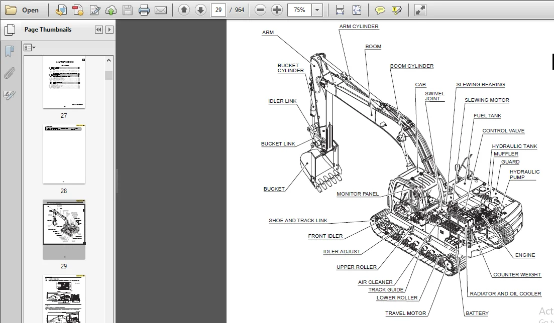
21 NAME OF COMPONENTS2-3
22 GENERAL DIMENSIONS 2-4
221 SK260–8 [602m (19ft-9in) Boom+298m (9ft-9in) Standard Arm+10m3
(13cu•yd) Bucket Shoe] 2-4
222 SK260–8 [602m (19t-9in) Boom+366m (12ft-0in) Long Arm+081m3
(106cu•yd) Bucket Shoe] 2-4
23 WEIGHT OF COMPONENTS2-5
24 TRANSPORTATION2-7
241 OVERALL DIMENSIONS OF MACHINE ON A TRAILER 2-7
242 DIMENSIONS OF ATTACHMENT2-8
25 SPECIFICATIONS AND PERFORMANCE2-10
251 SPEED AND CLIMBING CAPABILITY 2-10
252 ENGINE 2-10
253 HYDRAULIC COMPONENTS 2-10
254 WEIGHT2-10
26 TYPE OF CRAWLER2-11
27 COMBINATIONS OF ATTACHMENT2-12
28 ENGINE SPECIFICATIONS 2-13
281 SPECIFICATIONS2-13
3-ATTACHMENT DIMENSIONS
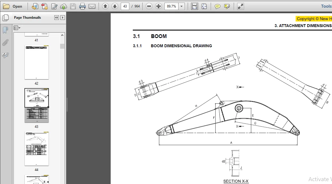
31 BOOM3-3
311 BOOM DIMENSIONAL DRAWING3-3
312 BOOM MAINTENANCE STANDARD3-4
32 ARM 3-6
321 ARM DIMENSIONAL DRAWING3-6
322 ARM MAINTENANCE STANDARD3-7
33 BUCKET AND PIN3-10
331 BUCKET AND PIN DIMENSIONAL DRAWING3-10
332 BUCKET AND PIN DIMENSIONAL TABLE3-11
MAINTENANCE SECTION
11-TOOLS
111 STANDARD TORQUE SPECIFICATIONS FOR CAPSCREWS AND NUTS11-3
112 SCREW SIZE11-5
1121 CAPSCREW (BOLT) 11-5
1122 CAPSCREW (SOCKET BOLT)11-5
1123 SOCKET SET SCREW11-5
113 TORQUE SPECIFICATIONS FOR HOSE AND FITTINGS11-6
1131 JOINT (O-RING TYPE)11-6
1132 HYDRAULIC HOSE (30° FLARE TYPE) 11-6
1133 JOINT (ORS TYPE) 11-6
1134 SPLIT FLANGE11-6
114 TORQUE SPECIFICATIONS FOR NUTS AND SLEEVES 11-7
115 PLUG 11-8
1151 PLUG FOR HYDRAULIC PIPE JOINT 11-8
1152 PLUG FOR HYDRAULIC EQUIPMENT 11-9
116 SPECIAL SPANNER FOR TUBE 11-11
117 SPECIAL TOOLS11-12
118 APPLICATION OF SCREW LOCKING COMPOUND AND SEALING COMPOUND11-14
119 SUCTION STOPPER11-15
1191 COMPONENTS 11-15
1192 DIMENSION11-15
1193 APPLICABLE MODEL 11-15
1110 COUNTER WEIGHT LIFTING JIG11-16
11110 UPPER FRAME LIFTING JIG11-17
1111 ENGINE TURNOVER STAND11-18
1113 TRACK SPRING SET JIG11-19
12-STANDARD MAINTENANCE TIMETABLE
121 STANDARD WORKING TIME TABLE FOR THE MAINTENANCE OF EXCAVATOR12-4
13-MAINTENANCE STANDARD AND TEST PROCEDURE
131 HOW TO USE THE MAINTENANCE STANDARD13-3
132 PERFORMANCE INSPECTION STANDARD TABLE13-4
133 MEASUREMENT OF ENGINE SPEED 13-6
1331 MEASUREMENT OF ENGINE SPEED13-6
134 MEASUREMENT OF HYDRAULIC PRESSURE13-7
1341 PREPARING TO MEASURE HYDRAULIC PRESSURE 13-7
1342 PLACE TO INSTALL PRESSURE GAUGE13-7
1343 PRESSURE ADJUSTMENT POSITION13-8
1344 PROCEDURE FOR ADJUSTING RELIEF VALVE13-10
135 MEASURING TRAVEL PERFORMANCES13-12
1351 TRAVEL SPEED13-12
1352 DEVIATION OF TRAVEL13-12
1353 PERFORMANCES OF PARKING BRAKE 13-13
1354 DRAIN RATE OF TRAVEL MOTOR13-14
136 MEASURING SWING PERFORMANCES13-15
1361 SWING SPEED13-15
1362 PERFORMANCE OF SWING BRAKE13-15
1363 PERFORMANCE OF SWING PARKING BRAKE 13-16
1364 DRAIN RATE OF SWING MOTOR13-17
137 MEASURING ATTACHMENT OPERATING PERFORMANCES 13-18
1371 OPERATING TIME OF CYLINDERS13-18
1372 CYLINDER LEAK CHECK13-19
138 MEASURING PERFORMANCES OF SWING BEARING13-20
139 MECHATRO CONTROLLER13-21
1391 ENGINE CONTROL INPUT / OUTPUT13-21
1392 ENGINE CONTROL13-22
1393 ADJUSTMENT OF MECHATRO CONTROLLER OUTPUT
(A-B-C ADJUSTMENT)13-24
1394 OPERATIONS IN THE EVENT OF A MECHATRO CONTROLLER FAILURE13-29
SYSTEM SECTION
21-MECHATRO CONTROL SYSTEM
211 SUMMARY OF MECHATRO CONTROL SYSTEM21-4
2111 MECHATRO CONTROL SYSTEM IN GENERAL 21-4
2112 UNLOAD VALVE CONTROL21-6
2113 POSITIVE CONTROL & P-Q CONTROL 21-7
2114 BOOM UP CONFLUX CONTROL 21-9
2115 ARM IN RECIRCULATION & CONFLUX CONTROL21-10
2116 ARM-IN ANTI-CAVITATION CONTROL21-12
2117 ARM-OUT CONFLUX CONTROL 21-13
2118 BUCKET DIGGING (DUMP) CONFLUX CONTROL 21-14
2119 BUCKET DIGGING ANTI-CAVITATION CONTROL 21-15
21110 SWING PRIORITY CONTROL 21-17
21111 TRAVEL STRAIGHT CONTROL 21-18
21112 TRAVEL INDEPENDENT CONTROL21-20
21112 PRESSURE RELEASE CONTROL21-22
21113 N&B SWITCH CONTROL (OPTION)21-23
21114 OPTION CONFLUX CONTROL (OPTION) 21-24
212 MECHATRO CONTROLLER21-25
2121 SUMMARY OF MULTI DISPLAY21-25
2122 SELF DIAGNOSIS DISPLAY21-30
2123 SERVICE DIAGNOSIS DISPLAY FUNCTION 21-31
2124 TROUBLE HISTORY DIAGNOSIS 21-42
2125 TROUBLE DIAGNOSIS MODE 21-43
2126 SET PROCEDURE OF MAINTENANCE SCHEDULE 21-43
2127 ADJUSTING PROCEDURE OF DISPLAY 21-44
2128 MECHATRO CONTROL EQUIPMENT 21-47
22-HYDRAULIC SYSTEM
221 SUMMARY22-3
222 HYDRAULIC CIRCUITS AND COMPONENTS22-4
223 COLOR CODING STANDARD FOR HYDRAULIC CIRCUITS22-8
224 NEUTRAL CIRCUIT22-8
225 TRAVEL CIRCUIT 22-10
226 BUCKET CIRCUIT22-12
227 BOOM CIRCUIT 22-14
228 SWING CIRCUIT 22-18
229 ARM CIRCUIT 22-20
2210 COMBINED CIRCUIT 22-26
2211 PRESSURE DRAINING (RELEASING) CIRCUIT 22-32
23-ELECTRICAL SYSTEM
231 ELECTRIC CIRCUIT DIAGRAM23-3
232 ELECTRICAL EQUIPMENT LIST23-8
233 HARNESS23-10
2331 HARNESS LIST 23-10
2332 INSTRUMENT PANEL ASSY23-11
2333 TUNER INSTALL23-12
2334 UPPER ELECTRIC ASSY 23-13
2335 UPPER FRAME HARNESS ASSY23-14
2336 UPPER FLOOR PLATE HARNESS ASSY23-20
2337 CAB HARNESS ASSY23-25
2338 BOOM HARNESS ASSY23-28
2339 INSTALLING BOOM LIGHT 23-28
23310 INSTALLING DECK LIGHT 23-29
23311 TRAVEL ALARM ASSY23-29
23312 FLASHER LAMP INSTALL23-35
24-COMPONENTS SYSTEM
241 HYDRAULIC COMPONENTS24-3
2411 HYDRAULIC PUMP, REGULATOR 24-3
2412 CONTROL VALVE24-21
2413 PILOT VALVE (ATT)24-59
2414 PILOT VALVE (TRAVEL)24-63
2415 SWING MOTOR 24-65
2416 TRAVEL MOTOR24-76
2417 SWIVEL JOINT24-93
2418 CYLINDER24-95
242 ELECTRIC EQUIPMENT24-100
2421 ELECTRIC EQUIPMENT LIST 24-100
2422 SPECIFICATION OF ELECTRIC EQUIPMENT 24-104
–
25-AIR CONDITIONER SYSTEM
251 BASIC AIR CONDITIONER SYSTEM (HVAC AIR CONDITIONER)25-3
2511AIR CYCLE 25-3
2512 AUTO AIR CONDITIONER SYSTEM OUTLINE 25-4
252 COMPONENT AND CONSTRUCTION 25-5
2521 COMPONENT25-5
2522 CONSTRUCTION25-6
253 PIPING25-9
2531 AIR CONDITIONER25-9
2532 RECEIVER DRYER ASSY 25-11
254 FUNCTION25-12
2541 MECHANISM OF COOLING CIRCUIT25-12
2542 COOLING CIRCUIT25-14
2543 COMPONENT PARTS25-15
255 DISASSEMBLY AND ASSEMBLY25-19
2551 PRECAUTIONS TO BE EXERCISED IN OPERATION25-19
2552 DISASSEMBLY AND ASSEMBLY OF UNIT 25-20
256 CHARGING REFRIGERANT25-24
2561 PRECAUTIONS TO BE EXERCISED IN OPERATION25-24
2562 OPERATING PROCEDURE25-25
2563 CHARGING PROCEDURE25-26
257 ELECTRIC CIRCUIT25-32
2571 WIRING DIAGRAM AND CONNECTORS25-32
2572 STRUCTURE AND OPERATION OF EACH PART AND INSPECTION25-34
258 TROUBLESHOOTING25-37
259 SELF DIAGNOSIS FUNCTION ON DISPLAY OF PANEL 25-44
2591 POSITION OF INDICATION FOR FAILURE 25-44
2592 EXPLANATION OF INDICATION FOR FAILURE 25-44
2593 EXPLANATION OF MONITOR MODE25-46
DISASSEMBLING SECTION
31-DISASSEMBLY AND ASSEMBLING
311 DISASSEMBLY & ASSEMBLY OVERVIEW31-3
3111 GENERAL INFORMATION31-3
3112 TORQUE SPECIFICATIONS31-3
32-ATTACHMENT
321 REMOVING AND INSTALLING 32-3
3211 ATTACHMENT ASSEMBLY32-3
3212 BUCKET 32-3
3213 ARM32-6
3214 BOOM32-9
322 DISASSEMBLING AND ASSEMBLING32-13
3221 CYLINDER32-13
33-UPPER STRUCTURE
331 REMOVING AND INSTALLING33-3
3311 OPERATOR SEAT 33-3
3312 CAB33-4
3313 BATTERY 33-6
3314 GUARD33-7
3315 UNDER COVER 33-13
3316 FUEL TANK 33-14
3317 HYDRAULIC TANK33-16
3318 HYDRAULIC PUMP33-20
3319 AIR CLEANER33-25
33110 MUFFLER33-26
33111 COUNTERWEIGHT33-28
33112 RADIATOR & OIL COOLER33-29
33113 ENGINE 33-35
33114 CONSOLE COVER33-38
33115 CONTROL VALVE33-39
33116 PILOT VALVE (FOR ATT) 33-42
33117 PILOT VALVE (FOR TRAVEL) 33-43
33118 SWING MOTOR 33-46
33119 SWIVEL JOINT33-48
33120 UPPER FRAME33-51
332 DISASSEMBLING AND ASSEMBLING33-54
3321 HYDRAULIC PUMP • REGULATOR 33-54
3322 CONTROL VALVE33-80
3323 PILOT VALVE (ATT)33-111
3324 PILOT VALVE (FOR TRAVEL) 33-121
3325 SWIVEL JOINT33-130
3325 SWIVEL JOINT33-163
34-TRAVEL SYSTEM
341 REMOVING AND INSTALLING34-3
3411 TRAVEL SYSTEM34-3
3412 CRAWLER34-3
3413 UPPER ROLLER 34-7
3414 LOWER ROLLER 34-13
3415 FRONT IDLER (IDLER ADJUSTER ASSY) 34-21
3416 SPROCKET 34-30
3417 TRAVEL MOTOR34-33
3418 SWING BEARING34-35
342 REMOVAL AND INSTALLATION OF TRAVEL MOTOR UNIT34-38
3421 CONSTRUCTION OF TRAVEL MOTOR34-38
TROUBLESHOOTING SECTION
46-TROUBLESHOOTING (BY ERROR CODES)
461 EVALUATION OF ACTUAL PROBLEM AT THE SITE46-3
462 CLASSIFICATION OF FAILURE AND TROUBLESHOOTING46-4
463 MECHATRO CONTROLLER BLOWN FUSE 46-4
464 TROUBLESHOOTING BY ERROR CODE46-4
47-TROUBLESHOOTING (BY SYMPTOM)
471 HYDRAULIC SYSTEM47-3
472 ELECTRIC SYSTEMS 47-27
4721 WIRING CHECKING PROCEDURE47-27
4722 TROUBLE47-30
473 ENGINE RELATED TROUBLESHOOTING47-33
48-TROUBLESHOOTING (BY DIAGNOSIS MODE)
481 TROUBLE DIAGNOSIS MODE 48-3
ENGINE SECTION
51-ENGINE
CHAPTER 1 – DIAGNOSTICS 1-1
CHAPTER 2 – 67 L T/A ENGINE OVERHAUL2-1
CHAPTER 3 – CHARGING AND START-UP3-
PLEASE NOTE:
- This is the same manual used by the dealers to diagnose and troubleshoot your vehicle
- You will be directed to the download page as soon as the purchase is completed. The whole payment and downloading process will take anywhere between 2-5 minutes
- Need any other service / repair / parts manual, please feel free to contact [email protected] . We still have 50,000 manuals unlisted


Oscar Quinn –