New Holland Crawler Excavator E80BMSR Service Repair Manual 87483766A – PDF DOWNLOAD
Original price was: $65.95.$23.95Current price is: $23.95.
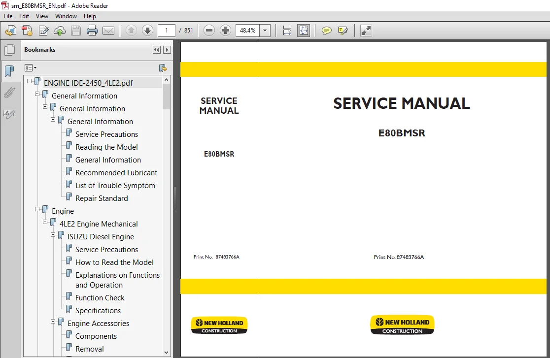
New Holland Crawler Excavator E80BMSR Service Repair Manual
Print No. 87483766A
Description
New Holland Crawler Excavator E80BMSR Service Repair Manual
FILE DETAILS:
New Holland Crawler Excavator E80BMSR Service Repair Manual
Language : English
Pages : 851
Downloadable : YES
Format : PDF
Size : 40.5 MB
Print No. 87483766A
DESCRIPTION:
New Holland Crawler Excavator E80BMSR Service Repair Manual
SAFETY PRECAUTIONS:
The serviceman or mechanic may be unfamiliar with many of the systems on this machine. This makes it important to use caution when performing service work. A knowledge of the system and or components is important before the removal or disassembly of any component. Because of the size of some of the machine components, the serviceman or mechanic should check the weights noted in this manual. Use proper lifting procedures when removing any components. Weight of components table is shown in the section .The following is a list of basic precautions that must always be observed.
(1) Read and understand all Warning plates and decal on the machine before Operating, Maintaining or Repairing this machine.
(2) Always wear protective glasses and protective shoes when working around machines. In particular, wear protective glasses when using hammers, punches or drifts on any part of the machine or attachments. Use welders gloves, hood/goggles, apron and the protective clothing appropriate to the welding job being performed. Do not wear loose fitting or torn clothing. Remove all rings from fingers, loose jewelry, confine long hair and loose clothing before working on this machinery.
(3) Disconnect the battery and hang a “Do Not Operate” tag in the Operators Compartment. Remove ignition keys.
(4) If possible, make all repairs with the machine parked on a firm level surface. Block the machine so it does not roll while working on or under the machine. Hang a “Do Not Operate” tag in the Operators Compartment.
(5) Do not work on any machine that is supported only by lift, jacks or a hoist. Always use blocks or jack stands, capable of supporting the machine, before performing any disassembly. Do not operate this machine unless you have read and understand the instructions in the OPERATOR’S MANUAL. Improper machine operation is dangerous and could result in injury or death.
(6) Relieve all pressure in air, oil or water systems before any lines, fittings or related items are disconnected or removed. Always make sure all raised components are blocked correctly and be alert for possible pressure when disconnecting any device from a system that utilizes pressure.
(7) Lower the bucket, dozer, or other attachments to the ground before performing any work on the machine. If this cannot be done, make sure the bucket, dozer, ripper or other attachment is blocked correctly to prevent it from dropping unexpectedly.
(8) Use steps and grab handles when mounting or dismounting a machine. Clean any mud or debris from steps, walkways or work platforms before using. Always face to the machine when using steps, ladders and walkways. When it is not possible to use the designed access system, provide ladders, scaffolds, or work platforms to perform safe repair operations.
(9) To avoid back injury, use a hoist when lifting components which weigh 20kg (45lbs) or more. Make sure all chains, hooks, slings, etc., are in good condition and are the correct capacity. Be sure hooks are positioned correctly. Lifting eyes are not to be side loaded during a lifting operation.
(10)To avoid burns, be alert for hot parts on machines which have just been stopped and hot fluids in lines, tubes and compartments.
TABLE OF CONTENTS:
New Holland Crawler Excavator E80BMSR Service Repair Manual
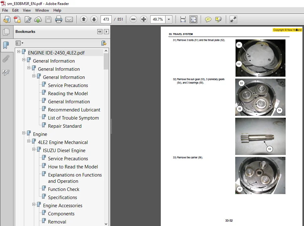
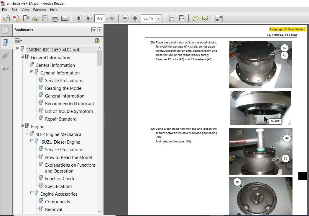
ENGINE IDE-2450_4LE2.pdf.............................................  0
	General Information..............................................628
		General Information..........................................628
			General Information......................................629
				Service Precautions..................................629
				Reading the Model....................................634
				General Information..................................635
				Recommended Lubricant................................641
				List of Trouble Symptom..............................642
				Repair Standard......................................651
	Engine...........................................................662
		4LE2 Engine Mechanical.......................................662
			ISUZU Diesel Engine......................................663
				Service Precautions..................................663
				How to Read the Model................................664
				Explanations on Functions and Operation..............664
				Function Check.......................................665
				Specifications.......................................672
			Engine Accessories.......................................673
				Components...........................................673
				Removal..............................................674
				Installation.........................................675
				Torque Specifications................................677
			Engine Exterior Equipment................................678
				Components...........................................678
				Removal..............................................681
				Installation.........................................687
				Torque Specifications................................696
			Rocker Arm Shaft.........................................697
				Components...........................................697
				Removal..............................................698
				Disassembly..........................................698
				Inspection...........................................698
				Reassembly...........................................700
				Installation.........................................701
				Torque Specifications................................702
			Cylinder Head............................................703
				Components...........................................703
				Removal..............................................704
				Disassembly..........................................705
				Inspection...........................................705
				Reassembly...........................................710
				Installation.........................................713
				Torque Specifications................................714
			Piston, Connecting Rod...................................715
				Components...........................................715
				Removal..............................................716
				Disassembly..........................................717
				Inspection...........................................718
				Reassembly...........................................722
				Installation.........................................723
				Torque Specifications................................725
			Flywheel.................................................726
				Components...........................................726
				Removal..............................................727
				Installation.........................................727
				Torque Specifications................................728
			Crankshaft Front Oil Seal................................729
				Components...........................................729
				Removal..............................................730
				Inspection...........................................731
				Installation.........................................731
				Torque Specifications................................733
			Crankshaft Rear Oil Seal.................................734
				Components...........................................734
				Removal..............................................735
				Installation.........................................735
				Torque Specifications................................736
			Timing Gear Train........................................737
				Components...........................................737
				Removal..............................................738
				Inspection...........................................738
				Installation.........................................740
				Torque Specifications................................741
			Camshaft.................................................742
				Components...........................................742
				Removal..............................................743
				Inspection...........................................743
				Installation.........................................746
				Torque Specifications................................747
			Crankshaft...............................................748
				Components...........................................748
				Removal..............................................749
				Disassembly..........................................749
				Inspection...........................................750
				Reassembly...........................................752
				Installation.........................................752
				Torque Specifications................................754
			Cylinder Block...........................................755
				Components...........................................755
				Removal..............................................756
				Inspection...........................................756
				Installation.........................................758
			Special Tool.............................................759
				List of Special Tool.................................759
	Engine...........................................................760
		4LE2 Cooling System..........................................760
			Cooling System...........................................761
				Service Precautions..................................761
				Explanations on Functions and Operation..............761
				Function Check.......................................763
			Water Pump...............................................766
				Components...........................................766
				Inspection...........................................766
			Thermostat...............................................767
				Inspection...........................................767
			Fan Clutch, Cooling Fan..................................768
				Inspection...........................................768
	Engine...........................................................770
		4LE2 Fuel System.............................................770
			Fuel System..............................................771
				Service Precautions..................................771
				Explanations on Functions and Operation..............772
			Governor.................................................775
				Service Precautions..................................775
				Components...........................................776
				Disassembly..........................................778
				Reassembly...........................................779
	Engine...........................................................784
		4LE2 Electrical System.......................................784
			Charging System..........................................785
				General Description..................................785
				Maintenance..........................................786
			Generator (24V-30A)......................................787
				Structure............................................787
				Removal..............................................788
				Installation.........................................788
				Torque Specifications................................789
				Specifications.......................................790
				Connector Terminal...................................790
				Internal Connections.................................790
				Components...........................................791
				Disassembly..........................................792
				Inspection...........................................794
				Reassembly...........................................795
				Bench Test...........................................795
				Trouble Diagnosis....................................797
				Maintenance Standard.................................797
			Generator (24V-50A)......................................798
				Structure............................................798
				Removal..............................................799
				Installation.........................................799
				Torque Specifications................................800
				Specifications.......................................801
				Connector Terminal...................................801
				Internal Connections.................................801
				Disassembly..........................................802
				Inspection...........................................803
				Bench Test...........................................805
				Handling.............................................807
				Trouble and Action...................................807
			Starting System..........................................808
				General Description..................................808
				Service Precautions..................................809
				List of Trouble Symptom..............................809
				Specifications.......................................810
				Sectional View.......................................811
			Starter..................................................812
				Components...........................................812
				Removal..............................................812
				Installation.........................................812
				Torque Specifications................................813
				Disassembly..........................................813
				Inspection...........................................815
				Reassembly...........................................818
				No Load Test.........................................821
				Maintenance Standard.................................821
	Engine...........................................................822
		4LE2 Exhaust System..........................................822
			EGR Control..............................................823
				Appearance of EGR Controller.........................823
				EGR Controller Wiring Diagram........................823
				Connector Pin Layout.................................824
				Engine Coolant Temperature Sensor Circuit Diagram....824
				Tachosensor Circuit Diagram..........................824
				Boost Pressure Sensor Circuit Diagram................825
				Engine Coolant Temperature Control...................825
				Engine Speed and Boost Pressure Control..............825
				Control When the Sensor Has an Open Circuit..........826
				Inspection...........................................826
	Engine...........................................................828
		4LE2 Lubrication System......................................828
			Lubrication System.......................................829
				Service Precautions..................................829
				Explanations on Functions and Operation..............829
				Function Check.......................................830
			Oil Filter...............................................831
				Removal..............................................831
				Installation.........................................831
			Oil Pump.................................................832
				Components...........................................832
				Inspection...........................................832
	Engine...........................................................834
		4LE2 Intake System...........................................834
			Turbocharger.............................................835
				Table of Specifications..............................835
				Structure............................................836
				Disassembly..........................................837
				Inspection...........................................840
				Reassembly...........................................843
				List of Measurement Tool.............................848
				List of Other Material...............................848
	Engine...........................................................850
		4LE2 Preheating System.......................................850
			Preheating System........................................851
				Explanations on Functions and Operation..............851
				Glow Plug Check......................................851
				List of Trouble Symptom..............................851
NEW HOLLAND CRAWLER EXCAVATOR E80BMSR SERVICE REPAIR MANUAL 87483766A – PDF DOWNLOAD:
IMAGES PREVIEW OF THE MANUAL:
PLEASE NOTE:
- This is not a physical manual but a digital manual – meaning no physical copy will be couriered to you. The manual can be yours in the next 2 mins as once you make the payment, you will be directed to the download page IMMEDIATELY.
- This is the same manual used by the dealers inorder to diagnose your vehicle of its faults.
- Require some other service manual or have any queries: please WRITE to us at [email protected]

Duke –
Fast and perfect!