
New Holland L565 LX565 LX665 Skid Steer Loader Service Repair Manual PDF
Original price was: $44.95.$26.95Current price is: $26.95.
Complete New Holland service and repair manual covering L565, LX565, and LX665 skid-steer loaders. Includes N844 and N844T engine service, troubleshooting, specifications, electrical and wiring information, hydrostatic and hydraulic repair, final drives, brakes, cab/boom components, and optional equipment.
Description
New Holland L565 LX565 LX665 Skid Steer Loader Service Repair Manual PDF
The New Holland L565 LX565 LX665 Skid Steer Loader Service Repair Manual PDF is a comprehensive service reference for the L565, LX565, and LX665 skid-steer loader range. The manual states that it provides the technical information needed to properly service and maintain these three models, and its coverage extends from general machine information through engine overhaul, electrical diagnosis, final drive work, hydrostatic and hydraulic system repair, cab and boom service, and optional equipment. Model-specific differences are identified throughout the book, including the naturally aspirated N844 diesel used in the L565 and LX565 and the N844T turbocharged diesel used in the LX665.
File Details
- Manual type: Service manual / repair and maintenance reference
- Brand: New Holland
- Models: L565, LX565, LX665 skid-steer loaders
- Language: English
- Pages: 827
- File format: PDF
Repair Information Built Around Complete Machine Systems
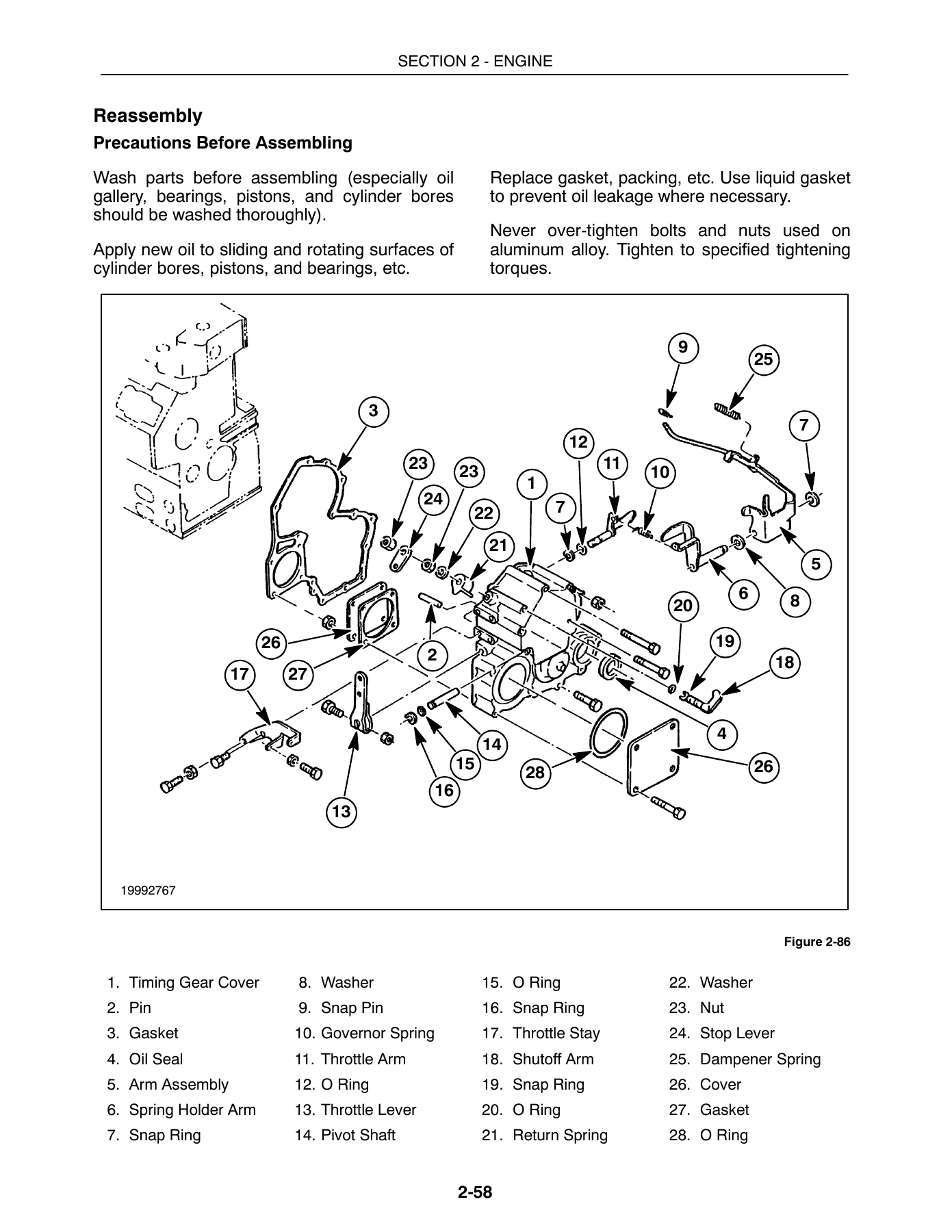
This New Holland skid-steer loader service manual is structured for hands-on diagnosis, disassembly, inspection, adjustment, reassembly, and testing. It does not stop at basic maintenance information. The engine section alone includes general engine data, troubleshooting charts, torque specifications, engine removal by two methods, a dismantling sequence, component inspection with fits and clearances, engine reinstallation, cooling and fuel systems, turbocharger service for the LX665, alternator and starter information, special tools, and labor guidance.
For engine work, the manual identifies the N844 engine for the L565 and LX565 and the N844T turbocharged engine for the LX665. Published service data includes bore and stroke, displacement, compression ratio, idle and high-speed ranges, horsepower and torque figures, valve clearances, firing order, fluid capacities, injection information, cooling data, lubrication requirements, electrical specifications, wear limits, and tightening torques. Inspection procedures cover parts such as the cylinder head, valve train, cylinder block, pistons and rings, connecting rods, crankshaft, bearings, camshaft, timing gears, oil pump, injection equipment, cooling components, and turbocharger. The LX665 material also includes dedicated turbocharger troubleshooting, lubrication precautions, removal, disassembly, inspection, clearances, and repair data.
Electrical coverage is similarly detailed. The electrical section contains specifications, wiring information, early- and later-model advanced warning systems, electrical circuits, component removal and installation, fuel-system electrical components, wire-harness information, alternator and starter service, and maximum circuit-resistance guidance. This makes the manual useful when a fault involves more than one system, such as a no-start condition that may involve the battery, fuses, switches, EIC circuits, fuel shutoff solenoid, glow-plug system, or starter circuit.
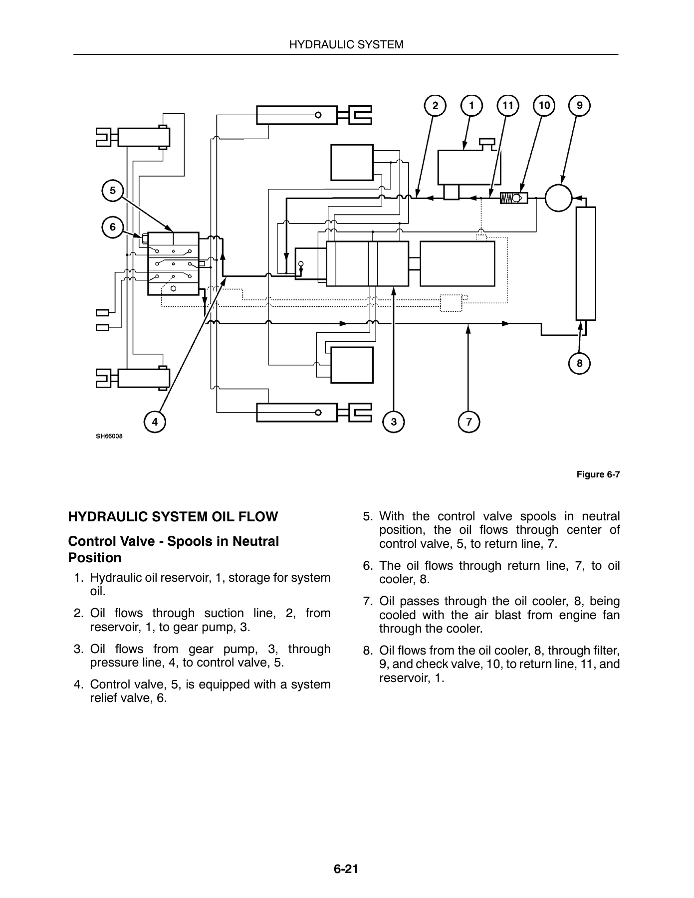
The drivetrain and hydraulic chapters support deeper mechanical repairs. Final drive, axles, parking brake, and gearboxes are treated as serviceable systems with specifications, troubleshooting and testing. The hydrostatic section covers drive-system testing, pumps, motors, hydraulic-system cleaning, post-rebuild start-up, the charge check valve, and steering controls. The separate hydraulic-system section adds compatibility information, system specifications, troubleshooting, pressure and flow testing, two control-valve configurations, the hydraulic pump, boom and bucket cylinders, and the cooling/filter/reservoir circuit. Diagrams show system oil flow and component relationships so procedures can be followed with the hydraulic circuit in context.
Specifications, Testing and Adjustment Data
The manual combines procedures with the numerical service data needed to carry them out correctly. General specifications include machine dimensions, operating weights, operating capacity, tire data, engine information, electrical-system data, hydraulic pressure and flow figures, cylinder dimensions and cycle times, hydrostatic charge and relief pressures, fluid capacities, and hardware and hydraulic fitting torque charts. Component chapters then add their own service limits, clearances, adjustment values, test conditions, and torque values.
Troubleshooting appears throughout the manual rather than being confined to a single chapter. Engine symptom charts address crank/no-start faults, irregular running, overheating, charging problems, starter faults, oil-pressure indications, smoke, power loss, turbocharger problems, and oil consumption. Fuel-system testing gives step-by-step checks for the electric fuel pump, shutoff solenoid, and fuel-level sender. Hydrostatic, hydraulic, electrical, final-drive, and optional-equipment sections provide their own diagnostic and testing material, helping narrow a fault before parts are removed.
Chapters Covered
- Section 1 – General Information
- Introduction and safety information
- Hardware torque specifications
- Hydraulic tube and fitting installation and torque specifications
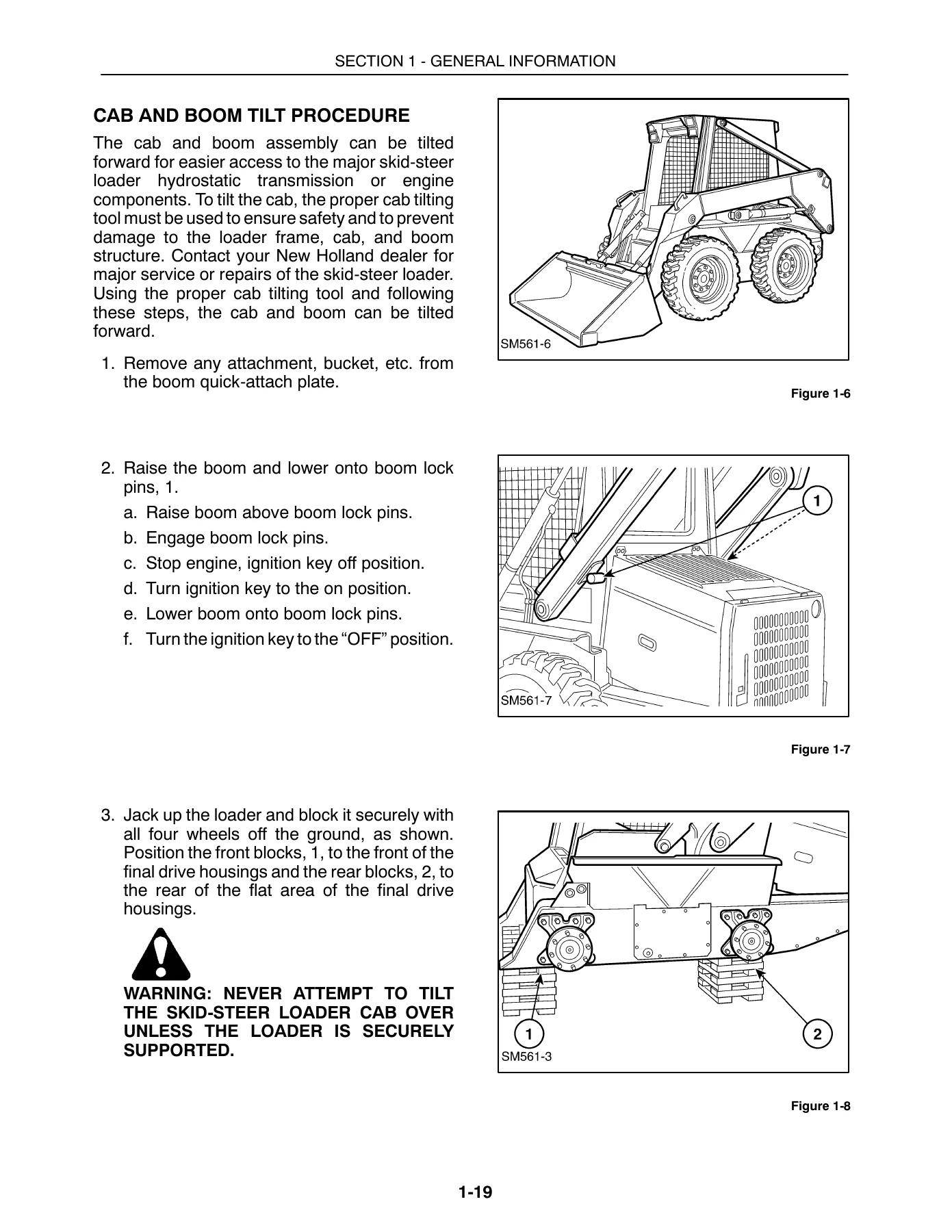
- Supporting a raised machine; cab and boom tilt procedure
- Craning the skid-steer loader
- 12V attachment power and hydraulic-system compatibility
- Accessory relay and engine fuse block
- Machine specifications
- Section 2 – Engine
- General engine information, model/serial-number location, and engine data
- Troubleshooting, specifications, and torque specifications
- Engine removal, dismantling, inspection, fits, and clearances
- Engine reinstallation and post-overhaul operation
- Cooling system and fuel system
- LX665 N844T turbocharger
- Alternator, starter, circuit resistance, special tools, and labor guide
- Section 3 – Electrical System
- General electrical information and specifications
- Wiring diagram
- Advanced Warning System – early model, silver frame
- Advanced Warning System – later model, gold frame
- Electrical circuits and electrical-component removal/installation
- Fuel-system electrical components and wire harness
- Alternator, starter, and maximum circuit resistance
- Section 4 – Final Drive, Axles, Brakes, Gearboxes
- General information and specifications
- Troubleshooting and testing
- Axles
- Final drive
- Parking brake
- Gearboxes
- Section 5 – Hydrostatic System and Steering System
- General information, specifications, and troubleshooting
- Hydrostatic drive system testing
- Hydrostatic pump removal, disassembly, inspection, reassembly, and installation
- Hydrostatic motor removal, disassembly, inspection, reassembly, and installation
- Hydraulic system cleaning and start-up after rebuild
- Charge check valve removal and replacement
- Steering system and hydrostatic system controls
- Section 6 – Hydraulic System
- General information and hydraulic-system compatibility
- Specifications, troubleshooting, and hydraulic-system testing
- Control valve with bolt-on solenoid blocks
- Control valve with threaded solenoid ports
- Hydraulic pump
- Boom and bucket cylinders
- Hydraulic cooling, filter, and reservoir system
- Section 7 – Seat, Cab, ROPS, Boom Lock, Boom, Attachment Mounting Plate
- General information
- Seat and cab inner shell
- ROPS frame
- Boom lock pin linkage
- Boom, upper and lower link
- Round-bar and square-bar attachment mounting plates
- Section 8 – Optional Equipment
- Auxiliary boom hydraulics and high-flow hydraulics
- Back-up alarm, block heater, and 12V electric power supply
- Buckets and related attachment checks
- Hand controls and heater/defroster
- Horn, road/work lights, warning lights, and rotary beacon
- Shoulder belt, SMV sign kit, tires/wheels, and rear counterweights
Taken as a whole, the New Holland L565 LX565 LX665 service repair manual provides a technician with a connected view of the machine rather than isolated repair notes. It supports work that begins with symptom diagnosis and system testing, continues through safe component removal and disassembly, and finishes with measurement, adjustment, reassembly, specified tightening, installation, and operational checks. The inclusion of wiring and hydraulic diagrams, service limits, model-specific engine information, serial-number breaks for selected components, and labor guides makes it especially useful for repairs where correct configuration and sequence matter.
IMAGES PREVIEW
Useful for L565, LX565 and LX665 Service Work
Because these models share many systems while differing in areas such as engine output and lifting capacity, the manual repeatedly separates common procedures from model-specific data. That is particularly important for the LX665, where the N844T turbocharged engine introduces dedicated lubrication, troubleshooting and turbocharger repair information. Early- and later-model component differences are also called out where applicable, including electrical and accessory arrangements.
Whether the job involves engine overhaul, injection timing, cooling-system repair, electrical fault tracing, hydrostatic drive diagnosis, pump or motor service, control-valve work, boom cylinder repair, axle or gearbox service, parking-brake adjustment, cab access, ROPS and boom components, or optional high-flow hydraulics, the manual provides procedures and supporting specifications in the same reference.
Get the Complete New Holland Service Reference
The New Holland L565 LX565 LX665 Skid Steer Loader Service Repair Manual PDF gives owners, mechanics, and technicians the information needed to diagnose faults, dismantle and inspect major assemblies, check wear limits and clearances, follow correct adjustment and reassembly procedures, and verify repairs against published specifications. Using the specified procedures, pressures, clearances, fluid data, torque values, wiring information, and system diagrams helps reduce guesswork when servicing these skid-steer loaders.
Delivery is instant as a PDF after payment, with no shipping delay. The manual can be viewed on a compatible phone, tablet, laptop, or desktop computer and printed as needed for workshop use.
Reviews
There are no reviews yet.