
New Holland TM115 TM125 TM135 TM150 TM165 Tractor Repair Manual
Original price was: $39.95.$23.95Current price is: $23.95.
New Holland TM-series repair coverage for engine, transmissions, axles, PTO, hydraulics, steering and electrical fault diagnosis in 1898 pages.
Description
New Holland TM115 TM125 TM135 TM150 TM165 Tractor Repair Manual
The New Holland TM115, TM125, TM135, TM150 and TM165 repair material brings mechanical overhaul and electronic diagnosis together in a substantial 1898-page PDF. The collected contents identify the TM115-TM165 repair manual and carry publication reference 87015506, dated 5/02. Its numbered sections follow the tractor from the engine and clutch through the transmission, axles, power take-off, brakes and hydraulic lift, finishing with extensive electrical diagnosis and wiring information.
This is a repair reference for a range of tractor configurations. Range Command, Dual Command, Shuttle Command and Power Command material appears in the transmission and electrical sections; open-centre and closed-centre load-sensing hydraulics are distinguished as well. Selecting the chapter for the installed equipment is part of using the volume correctly. The manual does not treat every TM tractor as if it has the same transmission, hydraulic pump or front axle.
File Details
- Type: tractor repair manual.
- Brand and models: New Holland TM115, TM125, TM135, TM150 and TM165.
- Contents publication reference: 87015506, 5/02.
- Language: English.
- Length: 1898 PDF pages.
- Format: PDF.
Chapters Covered
- Section 00 – General: health and safety.
- Section 10 – Engine: specifications, fuel test plans, tightening torques, special tools, fault finding, description and operation.
- Engine: removal and installation, overhaul, fuel-system components and cooling-system components.
- Section 18 – Clutch: specifications, sectional views, troubleshooting, removal and installation, hydraulic-control assembly.
- Section 21 – Transmission: Range Command, Dual Command, Shuttle Command and Power Command.
- Transmission: calibration, fault finding, pressure testing and limp-home procedures.
- Section 23 – Drive Lines.
- Section 25 – Mechanical Front Axle: front-axle service and Terraglide suspension.
- Section 27 – Mechanical Rear Wheel Drive.
- Section 31 – Power Take-Off.
- Section 33 – Brakes.
- Section 35 – Hydraulic Systems: hydraulic circuits, variable-flow pump and fixed-displacement arrangements.
- Hydraulic Systems: electronic draft control, mechanical rear hydraulic lift and remote-control valves.
- Section 41 – Steering: hydrostatic steering system.
- Section 44 – Front Axle and Wheels.
- Section 50 – Auxiliary Units: air conditioning.
- Section 55 – Electrical System: electronic management unit and instrument clusters.
- Electrical System: starting, charging, battery, wiring diagrams and component testing.
- Electrical System: diagnostic H routines and electrical harnesses.
The result is a workshop resource that connects component construction with operating descriptions, test points, adjustment data and diagnostic routines. It can support both a mechanical strip-down and investigation of a control-system fault, with the applicable configuration identified before work begins.
Engine service from measurements to cooling
The engine chapter includes fuel test plans, compression testing, cylinder-head work, front-cover and timing-gear work, oil-pan removal, connecting rods, bearings, pistons and rings. Cylinder-block overhaul, main bearings, flywheel, rear cover, oil seals, crankshaft, camshaft and oil-pump work are also named in the contents. Fuel-pump removal and timing, injectors, turbocharger, air cleaner, fuel tank and throttle cable appear alongside cooling-system components.
Service data include oil-pump clearances, minimum oil pressure at idle and rated speed, filter-support relief pressure and oil quantities with and without the filter. The cooling material identifies thermostat opening and fully-open ranges, radiator-cap pressure, belt drive and model-group cooling capacities. These details support planning a repair and checking measurements against the relevant specification rather than relying on a generic engine checklist.
Transmission choice changes the diagnostic route
The New Holland TM-series workshop material gives separate attention to transmission construction and transmission control. Range Command and Dual Command chapters include calibration, pressure tests, fault finding and limp-home information; Power Command has its own service and diagnostic coverage. The electrical section then supplies the appropriate wiring diagrams and diagnostic H routines. This separation is useful when the symptom could arise from a sensor, command input, hydraulic circuit or mechanical assembly.
Component testing extends to clutch-pedal potentiometers, speed sensors, range potentiometers, forward/reverse inputs, pressure switches and transmission-side-cover solenoids. The manual also identifies individual harness groups and their connectors. A technician can therefore follow an electrical symptom back toward a named component and then consult the transmission material for its mechanical or hydraulic function.
Hydraulic lift, pump systems and steering
The hydraulic chapters distinguish closed-centre load-sensing high-pressure circuits, open-centre high-pressure circuits and low-pressure services. Variable-flow-pump testing includes pressure and flow checks with separate low- and high-pressure standby material. Electronic draft control and mechanical rear-lift sections address their respective control arrangements rather than merging them into one procedure.
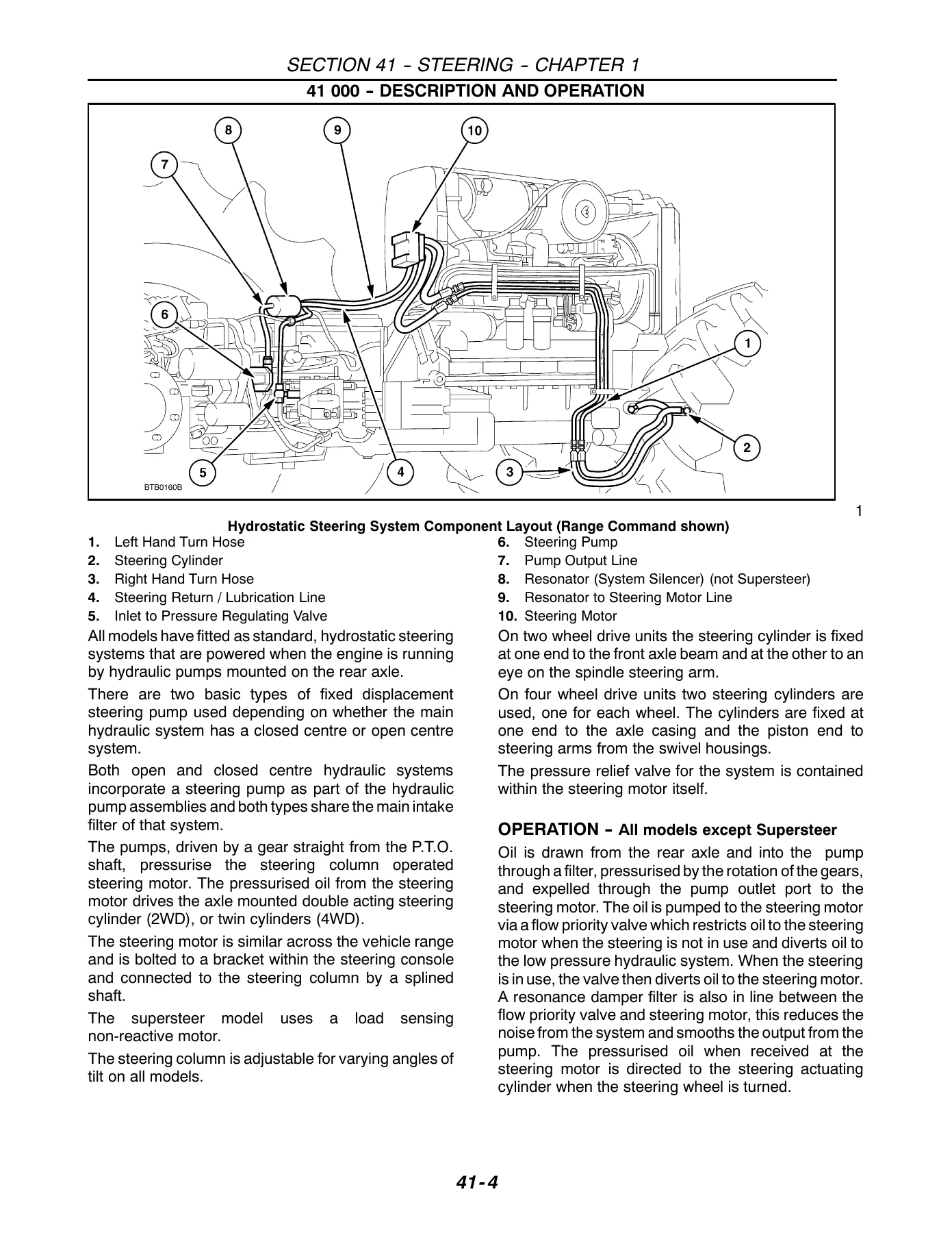
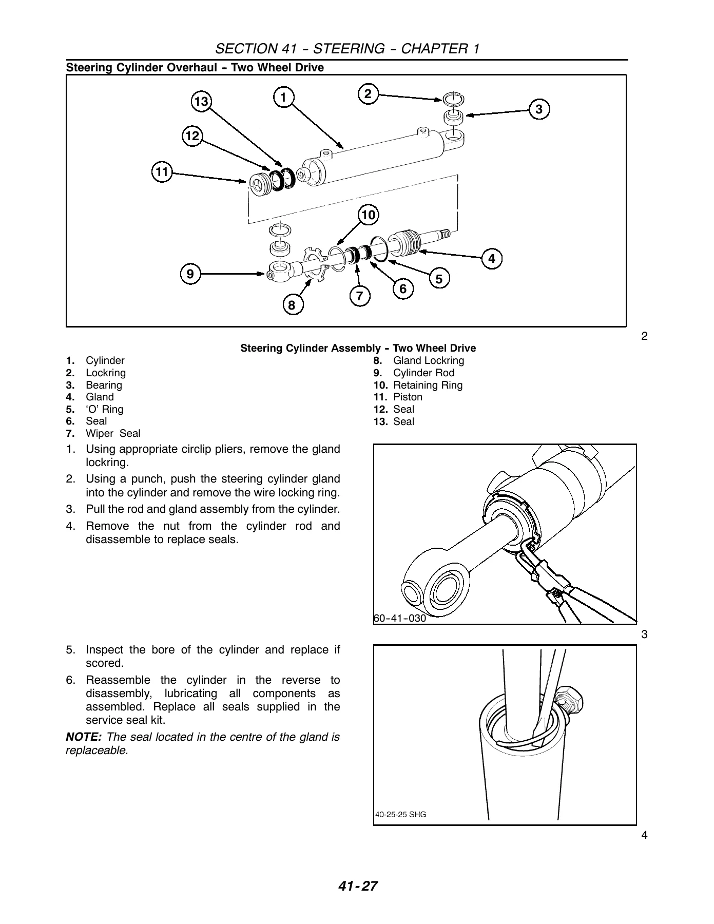
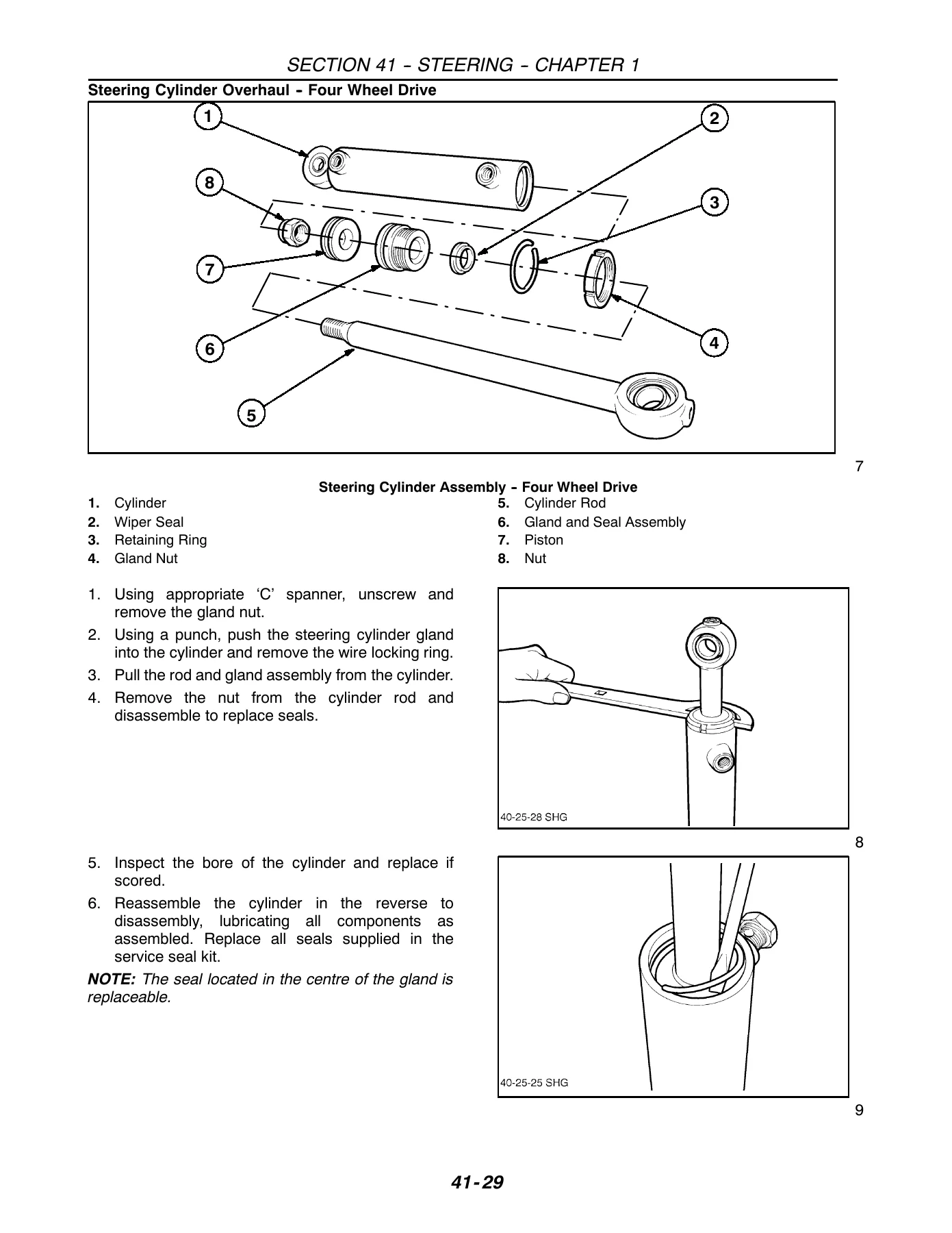
Lift specifications cover cylinder and piston dimensions, clearances, cross-shaft end float and valve settings. Mechanical-lift data extend to shaft and bush dimensions, spool clearances and spring dimensions. The steering chapter provides a component layout and separate two-wheel-drive and four-wheel-drive cylinder illustrations, with SuperSteer differences identified in the system description and specifications. Front-axle and Terraglide material completes the connection between hydraulic control and the physical steering or suspension assembly.
Electrical equipment and operator information
The electronic management unit section includes functions with and without Terralock, calibration, brake-switch adjustment, removal and installation, and error codes. Instrument coverage includes electronic, analogue-electronic and analogue clusters, with sender and switch information, serviceability and fault-finding material appropriate to each type. Starting, charging and battery sections include their own specifications and tests.
Wiring diagrams are grouped by transmission and cab configuration. The manual explains how to use the linear diagrams, identifies symbols and component locations, and supplies wire-identification keys. Electrical harness coverage includes lighting, front engine, rear transmission, cab and console groups. Air-conditioning service in the auxiliary-unit section broadens the repair scope to the operator environment.
Plan disassembly around the relevant assembly
The engine contents distinguish removal of the complete engine from overhaul of the individual assemblies. Cylinder-head work, timing gears and front cover, oil pan, pistons and connecting rods, crankshaft and camshaft are separate tasks. That organization lets a workshop identify the likely access work and tools before starting to dismantle the tractor. Fuel-pump timing and injector work are also clearly separated from the main engine strip-down, while radiator, fan, belt tensioner and water-pump procedures address the cooling installation around it.
Engine measurements include six cylinders, a bore of 111.8 mm and a stroke of 127.0 mm across the listed model group. The oil-pressure values carry an explicit normal-operating-temperature condition. Oil quantities distinguish the filter from the engine-only quantity, and the cooling chart separates the smaller and larger TM model groups. These are useful examples of why the service-data pages should stay beside the procedure throughout inspection and reassembly.
IMAGES PREVIEW
Read a lift complaint through its control system
A rear-lift complaint can involve the hydraulic supply, control valve, mechanical linkage or electronic command. The book provides separate coverage for hydraulic circuits, variable-flow-pump testing, electronic draft control and the mechanical rear lift. The component-testing contents include load-sensing pins, the EDC control unit, raise and lower solenoids, the lift-arm potentiometer and the electronic draft-control panel. Those subjects give the electronic side of the lift a defined place in diagnosis rather than treating every lifting symptom as a worn pump.
On the mechanical side, the rear-lift tables specify cross-shaft and bush dimensions, draft-control and position-control shaft clearances, and the fit of the control spool and pilot valve. Spring information includes free lengths and compressed lengths under stated loads. The associated illustrated procedures show how these pieces belong to the assembly. A dimensional check can therefore be related to the actual control or support being examined, not transferred to another component with a similar appearance.
Keep electrical symptoms connected to their inputs
The component-test list covers coolant-level and temperature devices, engine oil-pressure switches and senders, the air-filter restriction switch, water-in-fuel sensor, fuel sender, PTO speed sensor and hydraulic-filter switches. Other entries address steering-angle and transmission-control inputs. This breadth is valuable when a warning or operating complaint may be caused by a signal or connection rather than the system the warning names.
Instrument-cluster chapters identify their senders, sensors and switches and provide the serviceability or fault-finding material appropriate to the cluster type. The electronic-cluster contents include diagnostic memory and fault-code charts as well as programming of the central LCD and performance monitor. The electronic management unit material separately identifies functions, calibration and error codes. These divisions help keep the display, management unit and field component from being treated as the same diagnostic target.
Use the diagram conventions before tracing a circuit
The wiring section explains linear diagrams and symbols before presenting configuration-specific circuit groups. Component identification and location keys, wire identification, connector information and harness drawings form the link between a diagram and the tractor. Starting with the correct transmission and cab diagram helps preserve the meaning of a connector or wire reference through a test.
The starting and charging chapters add their own component procedures and checks. Alternator specifications distinguish the standard and optional output ratings, while battery maintenance, testing and charging receive dedicated coverage. Together with lighting and cab harness information, these sections support investigating both an isolated component fault and a wider electrical-supply complaint.
Use the TM repair information throughout the job
The New Holland TM115 TM125 TM135 TM150 TM165 Tractor Repair Manual supports diagnosis, removal, inspection, adjustment and reassembly across the tractor’s principal systems. Keeping the correct configuration, special-tool requirements and service values together helps avoid carrying a procedure from one transmission or hydraulic arrangement into another. Instant PDF delivery after payment means no shipping delay: consult the volume on a compatible computer, tablet or phone and print the specific diagrams and working pages required.
Reviews
There are no reviews yet.