NEW HOLLAND TN75FA, TN85FA, TN95FA SERVICE REPAIR MANUAL (87675643) NEW HOLLAND TN75FA – PDF Download
Original price was: $87.95.$36.95Current price is: $36.95.
- NEW HOLLAND TN75FA, TN85FA, TN95FA SERVICE REPAIR MANUAL
- Part No:87675643
Description
NEW HOLLAND TN75FA, TN85FA, TN95FA SERVICE REPAIR MANUAL (87675643) NEW HOLLAND TN75FA
File Details:
NEW HOLLAND TN75FA, TN85FA, TN95FA SERVICE REPAIR MANUAL
Size :42.6 MB
Format : PDF
Language : English
Number of Pages : 1460 pages
Brand: New Holland
Type of machine: Tractor
Type of document: Service Manual
Model: TN75FA, TN85FA, TN95FA
Part No: 87675643
NEW HOLLAND TN75FA, TN85FA, TN95FA SERVICE REPAIR MANUAL (87675643) NEW HOLLAND TN75FA – PDF DOWNLOAD:
Image Preview:
Description:
NEW HOLLAND TN75FA, TN85FA, TN95FA SERVICE REPAIR MANUAL (87675643) NEW HOLLAND TN75FA
- All maintenance and repair operations described in this manual should be carried out exclusively by the authorized workshops. All instructions detailed should be carefully observed and special equipment indicated should be used if necessary.
- Everyone who carries out service operations described without carefully observing these prescriptions will be directly responsible of deriving damages.
Table of Contents:
NEW HOLLAND TN75FA, TN85FA, TN95FA SERVICE REPAIR MANUAL (87675643) NEW HOLLAND TN75FA
SECTION 00 – GENERAL
BOOK 1 – 87675644
Chapter 1 – General
CONTENTS
Section Description Page
General Instructions 3
Health and Safety 5
Precautionary Statements 15
Safety 16
Ecology and the Environment 19
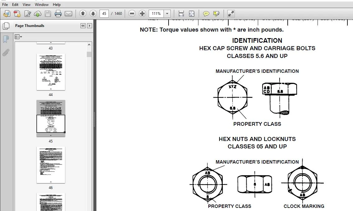
Minimum Hardware Tightening Torques 20
Federal Emissions Warranty 22
Consumables 25
SECTION 10 — ENGINE
BOOK 1 – 87675644
Chapter 1 — Engine
CONTENTS
Section Description Page
Specifications 2
Special Tools 10
Tightening Torques 12
Sectional Views 14
Troubleshooting 18
Overhaul 19
10 001 10 Engine 19
Removal 19
Installation 19
Compression Test 25
10 001 54 Disassembly 26
Assembly 27
Seal Installation 40
SECTION 10 — ENGINE
BOOK 1 – 87675644
Chapter 1 — Engine (Continued)
CONTENTS
Section Description Page
Checks, Dimensions and Repairs 50
Cylinder Block 50
Crankshaft 52
Main Bearings 54
Flywheel 55
Connecting Rods 56
Pistons 57
Valves 60
Valve Timing 60
Camshaft 61
Tappets 62
Cylinder Head 62
Valve Seats 63
Valve Guides 64
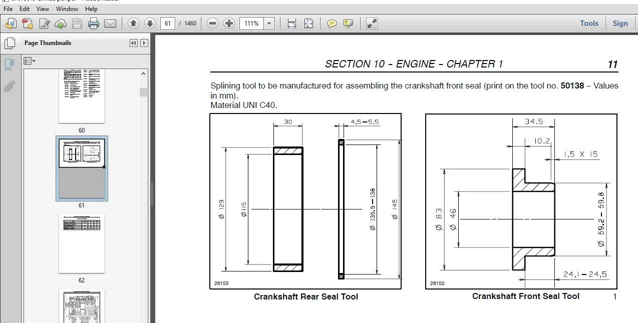
Crankshaft Front Oil Seal 67
10 102 70 Rotating Counterweight Dynamic Balancer 72
Valve/Rocker Arm 74
SECTION 10 — ENGINE
BOOK 1 – 87675644
Chapter 2 — Cooling System
CONTENTS
Section Description Page
Specifications 2
Special Tools 3
Sectional Views 4
Description and Operation 5
Cooling System 4
Radiator 4
Thermometer 4
Thermostat 4
Thermostatic Switch 4
Overhaul 6
10 406 10 Coolant Pump 6
Removal 6
Installation 10
Disassembly 11
Assembly 11
Drive Belt Tension Adjustment 12
10 402 30 Cooling System Thermostat 13
Removal 13
Installation 14
10 402 28 Radiator 15
Removal 15
Installation 18
SECTION 10 — ENGINE
BOOK 1 – 87675644
Chapter 3 — Lubrication System
CONTENTS
Section Description Page
Specifications 2
Special Tools 3
Sectional Views 4
Description and Operation 5
Oil Filter 5
Low Oil Indicator 5
10 001 10 Oil Pump 6
SECTION 10 — ENGINE
BOOK 1 – 87675644
Chapter 4 — Fuel System
CONTENTS
Section Description Page
Specifications 2
Special Tools 4
Tightening Torques 5
Description and Operation 6
Fuel Injection Pump (Bosch) 6
Turbocharged Models 6
All Models 8
Overhaul 10
10 218 30 Fuel Injectors 10
Removal 10
Installation 11
10 246 14 Injection Pump 12
Removal 12
Installation 16
Checking the Fuel Injection Pump Timing with the Pump on the Tractor 17
Lock-time the Fuel Injection Pump with the Pump Removed from the Tractor 21
Fuel Circuit Air Bleeding 26
SECTION 21 — TRANSMISSIONS
BOOK 2 – 87051829
Chapter 1 — Mechanical Transmission (16 x 16) Synchro-Command
CONTENTS
Section Description Page
21 000 Main data 2
Torque settings 2
Tools 4
Cross–sectional views 8
Description and operation 12
Troubleshooting 12
21 118 10 Rear transmission/gearbox casing Removal — Installation 14
21 118 85 Gearbox transmission casing Disassembly — Assembly 25
Transmission–Gearbox Casing 33
21 130 10 Gearbox control lever Removal — Installation 35
21 130 11 Range gear control lever Removal — Installation 36
SECTION 21 — TRANSMISSIONS
BOOK 2 – 87051829
Chapter 2 — 32 x 16 Dual Power with Electrohydraulic Power Shuttle
CONTENTS
Section Description Page
21 000 Main Data 2
Torque Settings 3
Tools 4
Description and operation 10
21 118 85 Transmission–Gearbox Disassembly — Assembly 11
21 154 34 Clutch Casing Disassembly — Assembly 14
21 134 46 Power Shuttle Control Valve Disassembly — Assembly 19
21 134 6 Accumulator Disassembly — Assembly 22
SECTION 21 — TRANSMISSIONS
BOOK 2 – 87051829
Chapter 3 — Power Shuttle Transmission Calibration,
Faults and Diagnostics
CONTENTS
Section Description Page
Fault Codes Indication 3
Description of Systems (ECM and CDU) 4
Automatic Self-Diagnosis (ECM) 5
ECM First Start Up (Self Configuration) 6
Transmission Disabled Indicators 7
ECM Diagnosis During Operation 9
Calibration and Diagnostics Unit (CDU) 10
Power Shuttle Fault Code Priority 11
Calibration and Diagnostic Unit Use 14
HH Menu Access 15
H1 — Clutches A and B Calibration 18
H2 — Clutches A and B Calibration Values Display 23
H3 — System Configuration 24
H4 — Software Revision Level 26
H5 — Control Switch Diagnosis 27
H6 — Clutch A Fill Time Modification and Display 32
H7 — Clutch B Fill Time Modification and Display 34
H8 — Erasure of Data Stored in the Non-Volatile
Memory (NVM) 36
H9 — Voltmeter Functions 37
HA — Clutch Pedal Potentiometer and Status Switch 41
Clutch Pedal Potentiometer Replacement and Clutch
Pedal Switch Adjustment 43
HC — Transmission Oil Temperature Sender 44
HD — Shuttle Synchronizer Operation 45
HE — Gear Change Adjustments 47
HF — Stored Error Codes 48
Troubleshooting Fault Codes 51
Description of Systems (ECM and EST) 52
Automatic Self-Diagnosis (ECM) 53
ECM First Start Up (Self Configuration) 54
Transmission Disabled Indicators 55
ECM Diagnosis During Operation 57
Power Shuttle Fault Code Priority 59
SECTION 21 — TRANSMISSIONS
BOOK 2 – 87051829
Chapter 3 — Power Shuttle Transmission Calibration,
Faults and Diagnostics (Continued)
CONTENTS
Section Description Page
Electronic Service Tool (EST) 62
Downloading the Latest Software into
TNFA Series Tractor Power Shuttle Control
Module with the Electronic Service Tool 63
Connecting the Electronic Service Tool
(EST) to the Tractor 67
H1 — Clutches A and B Calibration 71
H2 — Clutches A and B Calibration Values Display 76
H3 — System Configuration 77
H4 — Power Shuttle Hardware and Software
Revision Levels 79
H5 — Control Switch Diagnosis 80
H6 — Clutch A Fill Time Modification and Display 85
H7 — Clutch B Fill Time 87
H8 — Erasure of Data Stored in the Non-Volatile
Memory (NVM) 89
H9 — Voltmeter Functions 90
HA — Clutch Pedal Potentiometer and Status Switch 94
Clutch Pedal Potentiometer Replacement and Clutch
Pedal Switch Adjustment 96
HC — Transmission Oil Temperature Sender 97
HD — Shuttle Synchronizer Operation 98
HE — Gear Change Adjustments 100
HF — Stored Error Codes 101
Troubleshooting Fault Codes 104
SECTION 23 — FWD TRANSFER BOX AND AUTO FWD
BOOK 3 – 87051830
Chapter 1 — FWD Transfer Box
CONTENTS
Section Description Page
23 000 Main Specifications 1
Tightening Torques 2
Tools 3
Cross-Sectional Views 5
Description and Operation of the FWD Drive Gear 7
Troubleshooting 8
23 101 26 Transmission Shafts and Guard, Removal–Installation 9
23 101 40 Drive Gear Housing, Removal–Installation 10
23 202 52 Drive Gear Housing, Disassembly–Assembly 12
SECTION 23 — FWD TRANSFER BOX AND AUTO FWD
BOOK 3 – 87051830
Chapter 2 — Auto FWD, Calibration and Diagnostics
CONTENTS
Section Description Page
Automatic FWD Fault Codes 2
Calibration Using the CDU 3
HH — Menu Access 3
H3 — System Configuration 4
H4 — Software Revision Level 7
H5 — Control Switches Diagnosis 7
H8 — Deleting Data from the Non-Volatile Memory 8
H9 — Voltmeter Functions 9
HD — FWD Engagement Position 10
HF — Errors Stored in the Non-Volatile Memory of the ECM 10
First Start-Up 12
Electronic Service Tool (EST) 13
Downloading the Latest Software 13
Connecting the Electronic Service Tool (EST) to the Tractor 17
SECTION 23 — FWD TRANSFER BOX AND AUTO FWD
BOOK 3 – 87051830
Chapter 2 — Auto FWD, Calibration and Diagnostics (Continued)
CONTENTS
Section Description Page
HH Menu Access 20
H3 — System Configuration 21
H4 — Software Revision Level 24
H5 — Control Switches Diagnosis 24
H8 — Deleting Data from the Non-Volatile Memory 25
H9 — Voltmeter Functions 26
HD — FWD Engagement Position 27
HF — Errors Stored in the Non-Volatile Memory of the ECM 27
First Start-Up 29
Troubleshooting 30
ECM Location 31
SECTION 25 — FRONT AXLE (FWD)
BOOK 3 – 87051830
Chapter 1 — Front Axle (Super Steer Axle)
CONTENTS
Section Description Page
25 000 Main Data 1
Torque Settings 4
Tools 7
Cross-Sectional Views 10
Description and Operation 13
Troubleshooting 15
25 100 30 Front axle assembly Removal–Installation 16
25 102 15 Bevel drive and front axle differential housing Removal–Installation 25
25 102 20 Front axle bevel drive Overhaul 29
25 102 24 Front axle differential Overhaul 37
25 104 34 Front axle differential lock clutch assembly Overhaul 38
25 108 30 Front epicyclic final drive Removal–Installation 41
25 108 38 Wheel hub and steering knuckles Removal–Installation 46
25 108 46 Steering knuckle pins and bearings Replacement 49
44 511 80 Front wheels adjustment (Toe-in) 50
SECTION 27 — REAR MECHANICAL DRIVE
BOOK 3 – 87051830
Chapter 1 — Rear Mechanical Transmission
CONTENTS
Section Description Page
27 000 Main Data 1
Tightening Torques 3
Tools 5
Cross–Sectional Views 9
Description and Operation 12
Troubleshooting 12
27 106 16 Rear Transmission Gearbox Removal–Installation 14
27 110 10 Differential Lock Engagement Sleeve–Adjustment 20
27 120 10 Final Drive Box Assembly Removal–Installation 26
27 120 34 Drive Shaft Removal–Installation 28
27 120 32 Epicyclic Final Drive Removal–Installation 30
SECTION 31 — MECHANICAL POWER TAKE-OFF
BOOK 3 – 87051830
Chapter 1 — Servo-Assist PTO
CONTENTS
Section Description Page
31 000 Main Data 1
Troubleshooting 2
Tools 3
Tightening Torques 4
Independent Power Take-off Description and Operation 5
PTO Servo-Assist Valve Description and Operation 7
PTO Clutch Engagement/Oil Flow 8
PTO Clutch Disengagement/Oil Flow 9
PTO Clutch Servo Control Adjustment 10
Hydraulic PTO Servo Assist Cable Adjustment 11
PTO Engaged Switch Adjustment 12
31 112 20 Mechanical PTO Removal–Installation 13
PTO Brake 16
SECTION 33 — BRAKING SYSTEM
BOOK 3 – 87051830
Chapter 1 — Braking System
CONTENTS
Section Description Page
33 000 Main Data 1
Torque Settings 2
Cross-Sectional Views 3
Tools 5
Description and Operation 6
Troubleshooting 7
33 202 60 Right or Left-Hand Brake, Removal–Installation 9
33 202 46 Brake Hydraulic Pump (Master Cylinders), Removal–Installation 11
33 202 04 Brake Hydraulic System, Air Bleeding 16
33 110 40 Parking Brake Disks, Removal–Installation 18
33 110 08 Handbrake Control, Stroke Adjustment 20
SECTION 35 — HYDRAULIC SYSTEM
BOOK 4 – 87051831
Chapter 1 — High Pressure System Description and Operation
CONTENTS
Section Description Page
Precautionary Statements 2
Description and Operation 3
High-pressure System Hydraulic pump 4
Hydraulic System Configuration Table 5
Mechanically Controlled Rear Hydraulic Lift 6
HPL Lift-O-Matic (Fast Raise/Lower Control) 8
Rear Mechanical Hydraulic Power Lift (HPL) Control Valve Oil Flow 9
Remote Control Valves 12
Rear Remote Valve Arrangement 13
Rear Remote Valve Stacking 14
Rear Remote Valve Control Levers 14
Deluxe Quick-Release Couplers 15
Zero-pressure Return Port 15
Mid-mount Control Valves (Optional) 16
Switching Between Single and Double Acting Cylinders 17
Double-acting Valve with Automatic Detent Release and Float 18
Double-acting Valve Less Automatic Detent Release and Float 21
Single-acting Valve Less Automatic Release and Float 22
TN75FA, TN85FA, TN95FA (without Front HPL and PTO) Models With Mechanical
Shuttle Transmissions Hydraulic System Diagram 23
TN85FA, TN95FA (with power Shuttle and Rear Mechanical HPL)
Hydraulic System Diagram 25
Fault Codes 106
SECTION 55 — ELECTRICAL SYSTEMS
BOOK 6 – 87051833
Chapter 4 — Charging System
CONTENTS
Section Description Page
55 000 Technical information 1
Tightening torque 1
Description and operation 2
System testing and troubleshooting 4
55 301 Removal, re-installation and servicing 10
SECTION 55 — ELECTRICAL SYSTEMS
BOOK 6 – 87051833
Chapter 5 — Battery
CONTENTS
Section Description Page
55 000 Technical information 1
Description and operation 1
55 300 Removal and re-installation 2
Battery checking and maintenance 3
Charging the battery 4
Battery problems — Frequent causes 7
SECTION 55 — ELECTRICAL SYSTEMS
BOOK 6 – 87051833
Chapter 6 — Connectors
CONTENTS
Section Description Page
55 100 Electrical Circuit Connectors/Component Connectors Identification 2
Connector Location Points 7
Wire Color Coding 25
Connectors / Component Connectors 26
SECTION 55 — ELECTRICAL SYSTEMS
BOOK 6 – 87051833
Chapter 7 – Wiring Diagrams
CONTENTS
Section Description Page
How to Use Wiring Diagrams 1
2WD / Mechanical Diff Lock / Mechanical Lift / Less Cab 2
Auto 4WD / Hydraulic Diff Lock / Mechanical Lift / Less Cab 5
2WD / Mechanical Diff Lock / Mechanical Lift / With Cab 8
Auto 4WD / Hydraulic Diff Lock / Mechanical Lift / With Cab 12
Symbols Used in Electrical Diagrams 16
SECTION 90 — CAB, PLATFORM, AND BODYWORK
BOOK 6 – 87051833
Chapter 1 — Cab
CONTENTS
Section Description Page
Special Tools 2
90 150 10 Cab Removal — Installation 3
90 156 14 Cab Windows, Removal — Installation 11
90 160 16 Upright Seals, Removal — Installation 14
SECTION 90 — CAB, PLATFORM, AND BODYWORK
BOOK 6 – 87051833
Chapter 2 — Platform
CONTENTS
Section Description Page
90 110 35 Platform Assembly, Removal — Installation 2
SECTION 90 — CAB, PLATFORM, AND BODYWORK
BOOK 6 – 87051833
Chapter 3 — Bodywork
CONTENTS
Section Description Page
90 100 22 Hood Removal — Installation 2
90 100 80 Protective Grill Removal — Installation 3
90 100 84 Hood Guard Removal — Installation 4
90 110 14 Control Panel Guards Removal — Installation 5
90 114 10 Safety Frame Roof Removal — Installation 6
Please Note:
- This is the SAME exact manual used by your dealers to fix your vehicle.
- The same can be yours in the next 2-3 mins as you will be directed to the download page immediately after paying for the manual.
- Any queries / doubts regarding your purchase, please feel free to contact [email protected]

Vihaan Callum –