New Holland Tractor TC54, TC56, AL59 Utility Combine Service Repair Manual (6046496100) New Holland – PDF Download
Original price was: $84.95.$36.95Current price is: $36.95.
- New Holland Tractor TC54, TC56, AL59 Utility Combine Service Repair Manual
- Part No:6046496100
Description
New Holland Tractor TC54, TC56, AL59 Utility Combine Service Repair Manual (6046496100) New Holland
File Details:
New Holland Tractor TC54, TC56, AL59 Utility Combine Repair Manual_6046496100
Size: 14.4 MB
Format: PDF
Language: English
Number of Pages : 553 pages
Brand: New Holland
Type of document: Service Manual
Model: TC54, TC56, AL59 Utility Combine
Part No: 6046496100
NEW HOLLAND TRACTOR TC54, TC56, AL59 UTILITY COMBINE SERVICE REPAIR MANUAL (6046496100) NEW HOLLAND – PDF DOWNLOAD:
Image Preview:
Description:
New Holland Tractor TC54, TC56, AL59 Utility Combine Service Repair Manual (6046496100) New Holland
- This manual is subdivided in sections marked by two–digit numbers, with independent page numbering within each section. When one section is formed by more chapters, each new chapter starts from page 1.
- The paragraphs and information dealt with can be easily found out in the index, at the page of the relevant section, or in the table of contents at the beginning of the manual.
- At the bottom of each page there is the manual print number and the relevant publication/up–dating date. The pages of further up–dating shall have the same print number, followed by a two digit number (for example: 1st Up–dating 604.64.961.01; 2nd Up–dating 604.64.961.02; etc.) and the relevant publication date. Thesepages shall be completed by the new print of the index, duly revised.
- The information in this manual is up–dated at the date of the publication. As NEW HOLLAND continuously improves its product range, some information could be not up–dated due to modifications of technical or commercial type, as well as for suiting the law regulations of the different countries.
- In case of disagreement, refer to NEW HOLLAND Sales and Service networks.
Table of Contents:
New Holland Tractor TC54, TC56, AL59 Utility Combine Service Repair Manual (6046496100) New Holland
GENERAL INFORMATION
Introduction 2
Important information 2
General instruction 3
Shimming 3
Rotating shaft seals 3
O–ring seals 3
Sealing compounds 3
Cotter pins 3
Protecting the electronic/electrical systems during charging or welding 4
Spare parts 5
Tools 5
Safety regulations 6
Accident prevention 6
Safety rules 6
General guidelines 6
Start–up 8
Hydraulic systems 8
Wheels and Tyres 8
Removal and Re–fitting 8
Units of measure — conversion chart 9
Minimum hardware tightening torques 11
Explanation of machine serial numbers 12
Speed 13
SECTION 10 — ENGINE
Important information 2
Cylinder head screws 2
Valve clearance 2
Injector 3
Installation 5
System bleed 5
Filter change 6
Specifications 8
Tightening torques 16
Special tools 17
Troubleshooting 19
Description and operation 23
Engine overhaul — Introduction 29
Injection pump timing check 30
Engine disassembly and overhaul:
coupled cylinder head, valves and other parts 33
Engine front cover and timing gears 44
Oil pan 48
Flywheel 49
Rear cover plate 50
Oil pump 51
Oil pressure relief valve 53
Camshaft 54
Camshaft bearings 55
Pistons 57
Connecting rod bushing replacement 59
Cylinder block overhaul 60
Crankshaft 66
Engine compression test 75
CHAPTER 2 — COOLANT FILTER
Assembly 2
Assembly diagram 3
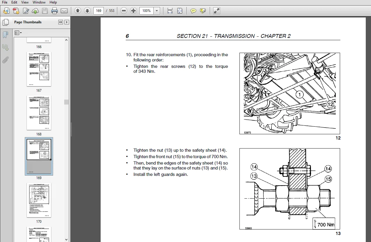
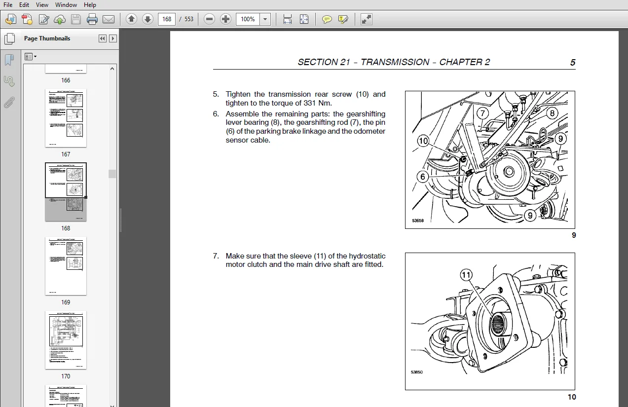
SECTION 21 — TRANSMISSION
CHAPTER 1 — TC TRANSMISSION
Mechanically–operated transmission, 4 gears 2
Hydrostatically–operated transmission, 4 gears 18
Mechanically–operated transmission, 3 gears 34
Assembly 45
Clutch 52
Clutch adjustments 53
Ground speed variator 57
CHAPTER 2 — AL TRANSMISSION
Transmission 2
Removal 2
Installation 4
Transmission 8
Preliminary remarks 8
Transmission disassembly 9
Transmission assembly 17
Transmission housing cover 32
Tools 33
SECTION 25 — FRONT MECHANICAL DRIVE
CHAPTER 1 — TC
Final drives 2
Removal 2
Assembly 3
CHAPTER 2 — AL
Final drives 2
Removal 2
Installation 4
Single stage final drive 8
Disassembly 8
Assembly 11
Tools 16
SECTION 29 — HYDROSTATIC TRANSMISSION
CHAPTER 1 — HYDRAULIC SYSTEM (TC)
Hydrostatic system diagram 2
Hydrostatic pump 4
Hydrostatic motor 6
Pump replacement 8
Motor replacement 8
System filling 9
Charge pump intake pressure 9
Input shaft replacement 10
Pressures 11
Hydrostatic system diagram 2
Hydrostatic pump 4
Hydrostatic motor 6
Pump replacement 8
Motor replacement 8
System filling 9
Oil and filter change 9
Charge pump intake pressure 9
Input shaft replacement 10
Pressures 11
CHAPTER 2 — HYDRAULIC SYSTEM (AL)
Hydrostatic system diagram 2
Hydrostatic pump 4
Hydrostatic motor 5
Pump drive pulley 6
SECTION 33 — BRAKES & CONTROLS
CHAPTER 1 — TC
Service brake 2
Removal 2
Assembly 2
Adjustment 2
Brake pedal adjustment 3
Brake master cylinder operation 4
Left circuit bleed 6
Bleed of the fitting between the two brake master cylinders 6
Right circuit bleed 7
Parking brake adjustment 7
Service brake 2
Removal 2
Assembly 2
Adjustment 2
Brake pedal adjustment 3
Brake master cylinder operation 4
Brake bleed 6
Left circuit bleed 6
Bleed of the fitting between the two brake master cylinders 6
Right circuit bleed 7
Parking brake adjustment 7
CHAPTER 2 — AL
Service brakes 2
Brake pedal adjustment 2
Brake master cylinder operation 3
Brake disc disassembly and replacement 5
Replacement of brake parts 7
Brake bleed 8
Parking brake 9
Replacement of brake parts 9
Parking brake disc — disassembly 10
6046496100 — 04 — 2003
SECTION 35 — HYDRAULIC SYSTEMS
CHAPTER 1 — TC
Hydraulic system components 2
Hydraulic valve functions 7
Explanation of symbols 8
Hydraulic pump 10
Hydraulic adjustment valve 12
Steering valve removal and installation 13
Hydropneumatic accumulator 22
Valve stack 23
Adjustment valve repair 25
Hydraulic cylinders 26
CHAPTER 2 — AL 59, LEVELLING AND PRESSURE CONTROL
Location of the hydraulic system main components 2
Power steering and hydraulic system line diagram 5
Location of the levelling hydraulic system main components 7
Location of the hydraulic system main components 8
Height compensation line diagram 9
Header side compensation 11
Header pressure limiting valve stack 13
Oil flow divider 13
Levelling control double pump 14
Pump identification data 14
Hydraulic cylinders 15
Cross levelling cylinder 18
Longitudinal levelling cylinder 20
Header cylinder 21
Header side compensation cylinder 22
Driving wheel control cylinder 23
SECTION 41 — STEERING
CHAPTER 1 — TC
Steering wheel spindle 2
Spindle disassembly 3
Spindle assembly 5
Steering wheel toe–in 7
Fixed steering axle 8
CHAPTER 2 — AL
Steering wheel spindle 2
Spindle disassembly 3
Spindle assembly 5
Steering wheel toe–in 7
SECTION 50 — CAB CLIMATE CONTROL
CHAPTER 1 — CLIMATE CONTROL SYSTEM
General information 2
A/C system utilization according to the law prescriptions 3
Storage conditions 3
A/C system circuit 4
Technical data 4
Coolant 4
Compressor 4
Compressor clutch 4
Components 6
Compressor 6
Condenser 7
Drying bottle 7
Expansion valve 8
Circuit parameters 9
Low pressure switch 9
High pressure switch 9
Drier filter 9
System filling 10
Electrical system 18
Troubleshooting 20
System flushing 32
CHAPTER 2 — COMPRESSOR
Compressor clutch replacement 2
Clutch removal 2
Clutch installation 6
SECTION 55 — ELECTRICAL SYSTEM
CHAPTER 1 — GENERAL INFORMATION
Diagram info 2
Wires 2
Symbols 3
Relays 5
Explanation of symbols 6
Location of main components 10
Ground speed calibration 16
Miscellaneous 17
CHAPTER 2 — WIRING DIAGRAMS
Electrical diagrams — Overview 2
List of symbols and where to find them 4
Electrical diagrams 21
Connectors 82
SECTION 60 — PRODUCT FEEDING
CHAPTER 1 — STRAW ELEVATOR
Straw elevator 2
Straw elevator chain 2
Lower shaft 3
Upper shaft 6
SECTION 66 — THRESHING
CHAPTER 1 — DRUM AND CONCAVE
Operating parts 2
Concave types 3
Concave adjustments 4
Concave replacement 6
Dust sheet 7
Threshing drum 8
Drum variator 10
Drum replacement 12
Threshing function adjustment 13
Threshing drum 14
Concave 15
Dust sheet 18
Stone trap 18
SECTION 72 — SEPARATION
Beater 2
Beater shaft, bearing and drive belt replacement 4
Straw walker and straw walker shaft replacement 6
Straw walker adjustment 13
SECTION 74 — CLEANING
CHAPTER 1
Fan variator replacement 2
Deflector and cleaning fan adjustment 3
Fan replacement 4
Grain pan and cleaning shoe removal 5
Upper and lower cleaning shoe removal and installation 6
Eccentric shaft 14
Upper and lower cleaning shoe removal —
Installation with sieve levelling cleaning system 15
Sieve levelling cleaning system upper sieve adjustment 17
Cleaning function adjustment 19
Introduction 19
Grain pan 20
Fan 21
Cleaning shoe 22
Self–levelling cleaning system 22
Adjustable sieve types 23
SECTION 80 — GRAIN STORAGE
CHAPTER 1 — CROP TRANSPORT
Lower augers 2
Grain tank filling auger 3
Tailing distribution auger 4
Unloading auger 5
SECTION 90 — CAB, PLATFORM, BODYWORK AND DECALS
CHAPTER 1
Introduction 2
Required tools 2
Broken windscreen removal 5
General instructions 10
Please Note:
- This is the SAME MANUAL used by the dealerships to diagnose your vehicle
- No waiting for couriers / posts as this is a PDF manual and you can download it within 2 minutes time once you make the payment.
- Your payment is all safe and the delivery of the manual is INSTANT – You will be taken to the DOWNLOAD PAGE.
- So have no hesitations whatsoever and write to us about any queries you may have : heydownloadss @gmail.com
Zev Ryder –