New Holland Tractor TN55, TN65, TN70, TN75 Service Repair Manual 87034092 – PDF DOWNLOAD
Original price was: $59.95.$39.95Current price is: $39.95.
New Holland Tractor TN55, TN65, TN70, TN75 Service Repair Manual
Part No: 87034092
Description
New Holland Tractor TN55, TN65, TN70, TN75 Service Repair Manual
FILE DETAILS:
New Holland Tractor TN55, TN65, TN70, TN75 Service Repair Manual
Size: 55.9 MB
Format: PDF
Language: English
Number of Pages: 886 pages
Brand: New Holland
Type of machine: Tractor
Type of document: Repair Manual
Model: TN55, TN65, TN70, TN75
Part No: 87034092
DESCRIPTION:
New Holland Tractor TN55, TN65, TN70, TN75 Service Repair Manual
GENERAL INSTRUCTIONS:
IMPORTANT NOTICE:
All maintenance and repair work described in this manual must be performed exclusively by NEW HOLLAND service technicians, in strict accordance with the instructions given and using any specific tools necessary. Anyone performing the operations described herein without strictly following the instructions is personally responsible for any eventual injury or damage to property.
BATTERY:
Before carrying out any kind of service operations, disconnect and isolate the battery negative lead, unless other- wise requested for specific operations (e.g.: operations that require the engine running). Once the specific operation has been completed, disconnect the lead in order to complete the operation.
SHIMMING:
For each adjustment operation, select adjusting shims and measure individually using a micrometer, then add up the recorder values. Do not rely on measuring the entire shimming set, which may be incorrect, or the rated value indicated for each on shim.
ROTATING SHAFT SEALS:
For correct rotating shaft seal installation, proceed as follows:
— before assembly, allow the seal to soak in the oil it will be sealing for at least thirty minutes;
— thoroughly clean the shaft and check that the working surface on the shaft is not damaged;
— position the sealing lip facing the fluid; with hydrodynamic lips, take into consideration the shaft rotation direction and position the grooves so that they will deviate the fluid towards the inner side of the seal;
— coat the sealing lip with a thin layer of lubricant (use oil rather than grease) and fill the gap between the sealing lip and the dust lip on double lip seals with grease;
— insert the seal in its seat and press down using a flat punch, do not tap the seal with a hammer or mallet;
— whilst inserting the seal, check that the it is perpendicular to the seat; once settled, make sure that it makes contact with the thrust element, if required;
— to prevent damaging the seal lip on the shaft, position a protective guard during installation operations.
O–RING SEALS:
Lubricate the O–RING seals before inserting them in the seats, this will prevent them from overturning and twist-
ing, which would jeopardise sealing efficiency.
SEALING COMPOUNDS:
Apply one of the following sealing compounds on the mating surfaces marked with an X: LOCTITE 518, LOC-TITE 5205, SUPERBOND 559 MASCHERPA or BETABLOCK A272M GURIT ESSEX.
Before applying the sealing compound, prepare the surfaces as follows:
— remove any incrustations using a metal brush;
— thoroughly de–grease the surfaces using one of the following cleaning agents: trichlorethylene, petrol or a
water and soda solution.
TABLE OF CONTENTS:
New Holland Tractor TN55, TN65, TN70, TN75 Service Repair Manual
Chapter 1 — General Instructions
CONTENTS
Section Description Page
10 000 General Instructions 1
SECTION 10 — ENGINE
BOOK 1 – 87034093
Chapter 1 — Engine
CONTENTS
Section Description Page
10 000 General specifications 2
Data 5
Torque settings 22
Tools 23
Cross–sectional views 25
Lubrication and cooling system diagrams 27
Troubleshooting 29
10 001 10 Engine, Removal–Installation 33
10 001 30 Compression test 35
10 001 54 Engine, Removal–Assembly 36
10 414 10 Coolant Pump and Alternator Drive Belt — Tension adjustment 72
10 101 53 Valve guides, Replacement 73
10 101 60 Injector holder casing, Replacement 76
10 102 70 Front engine oil seal, Removal–Installation 78
10 106 12 Valve clearance adjustment 80
10 126 10 Fuel tank, Removal–Installation 82
10 218 30 Engine injectors, Removal–Installation 84
10 246 14 Bosch injection pump, Removal–Installation, timing and air bleed check 86
10 254 44 Exhaust pipe, Removal–Installation 92
10 402 11 Coolant pump, Removal–Installation, with radiator removed 93
10 402 28 Coolant pump, Overhaul 94
10 402 30 Thermostat, Removal–Installation 95
10 406 10 Radiator, Removal–Installation 97
3
SECTION 18 — CLUTCH
BOOK 1 – 87034093
Chapter 1 — Clutch
CONTENTS
Section Description Page
18 000 General specifications 1
Torque settings 2
Tools 2
Cross–sectional views 3
Troubleshooting 5
18 110 10 Clutch — Removal–Installation 6
18 110 30 11/11 Dual disk clutch — Test bench overhaul 11
18 110 30 11 Single disk clutch (Version with Power–Shuttle) — Test bench overhaul 15
18 100 40 Clutch adjustments 19
SECTION 21 — TRANSMISSIONS
BOOK 2 – 87034094
Chapter 1 — Mechanical Transmission (8 x 8),
(16 + 16) Synchro-Command, and 8 x 8 Non-Synchronized Transmissions
CONTENTS
Section Description Page
21 000 Main data 1
Torque settings 2
Special Tools 4
Cross-sectional views 8
Description and operation 14
Troubleshooting 14
21 118 10 Rear Transmission/Gearbox, Removal–Installation
21 118 12 16
21 118 85 Rear Transmission/Gearbox, Disassembly–Assembly 23
Rear Transmission/Gearbox, driving and driven shafts clearance adjustments 31
21 130 10 Gearbox Control Lever, Removal–Installation 33
21 130 11 Range Gear Control Lever, Removal–Installation 34
4
SECTION 21 — TRANSMISSIONS
BOOK 2 – 87034094
Chapter 2 — Power Shuttle Transmission (8 + 8 and 16 + 16 versions)
CONTENTS
Section Description Page
21 000 Main data 2
Torque values 4
Special tools 5
Cross-sectional views 10
Description and operation 15
21 118 85 Transmission–Gearbox, Disassembly–Assembly 16
21 134 46 Power shuttle control valve, Disassembly–Assembly 18
21 134 70 A + B Clutch valve solenoids, Removal–Installation 21
21 134 70 Dump valve solenoid, Removal–Installation 22
21 154 34
21 154 60 Clutch casing, Disassembly–Assembly 23
Description of systems (ECM and CDU) 28
Automatic self-diagnosis (ECM) 29
ECM First start up 30
Diagnosis during operation 31
Calibration and diagnostic unit (CDU) 32
Power shuttle fault code priority 33
Fault codes indication 36
Calibration and diagnostics unit use 37
HH menu access 38
H1 — Clutches A and B calibration error codes 40
H2 — Clutches A and B calibration values display 45
H3 — System configuration 46
H4 — Power shuttle hardware and software revision levels 48
H5 — Control switch diagnosis 49
H6 — Clutch A fill time 54
H7 — Clutch B fill time 56
H8 — Erasure of data stored in NVM 58
H9 — Voltmeter functions 59
HA — Clutch pedal potentiometer and status switch 63
Clutch pedal potentiometer replacement 65
5
SECTION 21 — TRANSMISSIONS
BOOK 2 – 87034094
Chapter 2 — Power Shuttle Transmission (8 + 8 and 16 + 16 versions)
(Continued)
CONTENTS
Section Description Page
HC — Transmission oil temperature sender 66
HD — Hi/Lo Synchronizer operation (not used in standard) 67
HE — Gear change adjustments 69
HF — Stored error codes 70
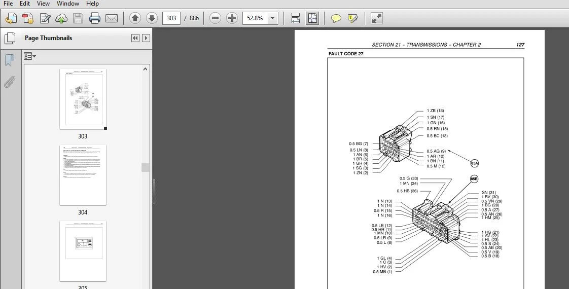
Troubleshooting fault codes 72
Power Shuttle (8 x 8 and 16 x 16) electronic control unit input/output wiring diagram 276
SECTION 23 — DRIVE LINES
BOOK 3 – 87034095
Chapter 1 — Drive Lines
CONTENTS
Section Description Page
23 000 Main data 1
Torque settings 2
Cross–sectional views 3
Description, operation and hydraulic diagrams 7
Troubleshooting 7
23 101 26 Transmission shafts and guard, Disassembly — Assembly 8
23 101 40 Drive gear housing assembly, Removal — Installation 9
23 202 50 Drive gear housing assembly, Removal — Installation 9
23 101 42 Drive gear housing assembly removed, Disassembly — Assembly 11
23 202 52 Drive gear housing assembly removed, Disassembly — Assembly 13
6
SECTION 25 — FRONT AXLE MECHANICAL TRANSMISSION
BOOK 3 – 87034095
Chapter 1 — Front Axle Mechanical Transmission
CONTENTS
Section Description Page
25 000 Main Data 1
Torque Settings 4
Tools 7
Cross–sectional Views 10
Description and Operation 11
25 100 30 Front Axle, Removal–Installation 12
25 108 30 Front Epicyclic Final Drive, Disassembly–Assembly 16
25 108 46 Steering Knuckle Bearing Pins, Replacement 22
25 100 38 Wheel Hubs and Steering Knuckle Pins and Bearings, Removal–Replacement–Installation 22
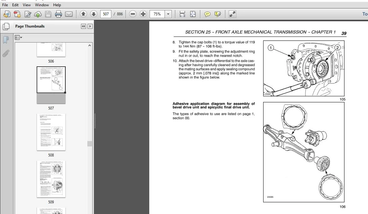
25 100 38 Bevel Drive and Front Axle Differential Axle Housing, Disassembly–Assembly 25
25 102 20 Front Axle Bevel Drive, Overhaul 30
Bevel Drive Adjustments 33
25 102 24 Front Axle Differential, Overhaul 40
25 102 27 Front Axle Differential with LIM–Slip Unit, Overhaul 41
44 511 80 Leading Drive Wheels Toe-in Check 43
SECTION 27 — REAR MECHANICAL TRANSMISSION
BOOK 3 – 87034095
Chapter 1 — Rear Mechanical Wheel Drive
CONTENTS
Section Description Page
27 000 Main data 1
Torque settings 3
Tools 5
Cross-sectional views 9
Description and operation 11
Troubleshooting 11
7
SECTION 27 — REAR MECHANICAL TRANSMISSION
BOOK 3 – 87034095
Chapter 1 — Rear Mechanical Wheel Drive (Continued)
Section Description Page
27 106 16 Rear Transmission/Gearbox, Removal–Installation 12
27 110 10 Differential Lock Engagement Sleeve, Adjusting 18
27 120 10 Final Drive Housing Assembly, Removal–Installation
27 120 20 25
27 120 34 Drive Wheel Shaft, Removal–Installation 27
27 120 32 Epicyclic Final Drive, Removal–Installation 29
SECTION 31 — MECHANICAL POWER TAKE–OFF
BOOK 3 – 87034095
Chapter 1 — Mechanical Power Take–Off
CONTENTS
Section Description Page
31 000 Main data 1
Tools 3
Tightening torque 4
Cross-sectional views 4
Description and operation 6
Troubleshooting 7
31 112 20 Mechanical power take-off, Removal–Installation 8
8
SECTION 33 — BRAKING SYSTEM
BOOK 3 – 87034095
Chapter 1 — Braking System
CONTENTS
Section Description Page
33 000 Main data 1
Torque settings 2
Cross-sectional views 3
Tools 4
Description and operation 5
Troubleshooting 6
33 202 60 Right or left–hand brake, Removal–Installation 8
33 202 46 Braking system hydraulic pump, Removal–Installation 10
33 202 04 Brake hydraulic system — Air Bleeding 15
33 110 40 Parking brake, Brake disks Removal–Installation
33 110 44 17
33 110 08 Handbrake control, Travel adjustment 18
SECTION 35 — HYDRAULIC SYSTEM
BOOK 4 – 87034096
Chapter 1 — Rear Mechanical Hydraulic Lift
CONTENTS
Operation Description Page
35 000 Main data 1
Torque settings 3
Tools 5
Cross-sectional views 7
Description and operation 12
Troubleshooting 16
35 110 40 Lift internal controls, Disassembly–Assembly 18
Lift adjustments 22
35 110 08 Tie-rod adjustments 28
Various adjustments 30
35 110 42 Lift cylinder and arms shaft, Disassembly–Assembly 32
35 114 14 Lift control valve (with control valve removed), Disassembly–Assembly 36
35 114 30 Lift pressure relief valve, Removal–Installation 40
35 114 32 Lift pressure relief valve (Setting) 40
9
SECTION 35 — HYDRAULIC SYSTEM
BOOK 4 – 87034096
Chapter 2 — Open Centre System Auxiliary Control Valves
CONTENTS
Operation Description Page
35 000 Main data — Tools — Torque settings 2
Cross-sectional views 3
Description and operation 5
Troubleshooting see Lift — Chapter 1
35 204 46 Auxiliary control valves, Disassembly–Assembly (with the unit removed) 9
SECTION 35 — HYDRAULIC SYSTEM
BOOK 4 – 87034096
Chapter 3 — Trailer Brake Auxiliary Control Valve
CONTENTS
Operation Description Page
35 000 Description and operation 1
Cross-sectional view 1
Troubleshooting 8
33 220 40 Trailer brake valve, Removal–Installation 11
SECTION 35 — HYDRAULIC SYSTEM
BOOK 4 – 87034096
Chapter 4 — Non–Stop Flow Gear Pump
Operation Description Page
35 000 Main data 1
Torque settings — Description and operation 2
Troubleshooting see Lift — Chapter 1
35 104 30 Lift circuit hydraulic pump, Disassembly–Assembly (with unit removed) 4
10
SECTION 41 — STEERING
BOOK 4 – 87034096
Chapter 1 — Steering
Operation Description Page
41 000 Torque settings main data — tools 2
Operation 3
Components 6
Troubleshooting 7
41 204 10 Hydrostatic steering wheel, Replacement 9
41 204 30 Hydrostatic steering control valve, Removal — Installation 10
41 204 34 Hydrostatic steering control valve, (removed) Disassembly — Assembly 15
41 204 38 Hydrostatic steering control valve — Bench testing 30
SECTION 41 — STEERING
BOOK 4 – 87034096
Chapter 2 — Non–Stop Flow Gear Pump
Operation Description Page
41 000 Main data 1
Torque settings — Description and operation 2
Troubleshooting see Lift — Chapter 1 Section 35
41 206 20 Power steering oil pump Disassembly — Assembly (with unit removed) 3
11
SECTION 44 — AXLES AND WHEELS
BOOK 4 – 87034096
Chapter 1 — Axles and Wheels
CONTENTS
Section Description Page
44 000 Main data 1
Cross–sectional views 3
Torque settings 4
Tools 6
Troubleshooting 7
44 101 22 Front axle hub, Removal–Installation 8
44 101 30 Front axle, Removal–Installation 11
44 101 46 Stub axle, Overhaul 14
44 511 80 Checking the alignment of the leading wheels 18
SECTION 55 — ELECTRICAL SYSTEM
BOOK 5 – 87034097
Chapter 1 –Instruments
CONTENTS
Section Description Page
55 000 Analog instruments 2
Controls 4
Transmitters, sensors and switches 6
12
SECTION 55 — ELECTRICAL SYSTEM
BOOK 5 – 87034097
Chapter 2 — Starting System
Section Description Page
55 000 Technical information 1
Torque settings 1
Description and operation 2
Troubleshooting 3
System testing 4
55 201 50 Starter motor, Removal–Installation 6
55 201 54 Starter motor, Disassembly–Assembly 7
Bench tests 9
SECTION 55 — ELECTRICAL SYSTEM
BOOK 5 – 87034097
Chapter 3 — Charging System
Section Description Page
55 000 Technical information 1
Torque settings 1
Description and operation 2
System testing and troubleshooting 4
55 301 10 Alternator, Removal–Installation 9
55 301 12 Alternator, Removed, Disassembly–Assembly 14
13
SECTION 55 — ELECTRICAL SYSTEM
BOOK 5 – 87034097
Chapter 4 — Battery
CONTENTS
Section Description Page
55 000 Technical information 1
Description and operation 1
55 301 40 Battery removal–Installation 2
Battery checking and maintenance 3
Battery charging 4
Battery problems — frequent causes 6
SECTION 55 — ELECTRICAL SYSTEM
BOOK 5 – 87034097
Chapter 5 — Electrical Circuits
(Before S/N 1268128)
CONTENTS
Section Description Page
55 000 Fuses and relays (Model with cab) 2
Symbols used in electrical circuits 4
Electric wire colour code 5
General diagram — Central part (electrohydraulic 4WD version ISO version) 6
General diagram — Central part (mechanical 4WD version ISO version) 9
General diagram — Front part (ISO version) 10
General diagram — Rear part (ISO version) 13
Lighting circuit diagram (ISO version) 14
Electrohydraulic 4WD and brake lights circuit diagram 15
Mechanical 4WD and brake lights circuit diagram 16
Front corner lights and rear work lights circuit diagram 17
General diagram — Central part (Power Shuttle version NASO version) 18
General diagram — Central part (Standard version NASO version) 21
General diagram — Front part (NASO version) 22
General diagram — Rear part (NASO version) 23
Lighting circuit diagram (NASO version) 24
14
SECTION 55 — ELECTRICAL SYSTEM
BOOK 5 – 87034097
Chapter 6 — Electrical Circuits
(After S/N 1268128)
Section Description Page
55 000 Electrical circuit components 2
Location of fuses and relays (mechanical shuttle and power shuttle versions) 4
Symbols used in electrical circuits 7
Electric wire color code 9
How to use the linear wiring diagrams 10
Electrical circuits (mechanical shuttle and power shuttle versions) 11
Ground location points (mechanical shuttle and power shuttle versions) 11
Front part circuit (mechanical shuttle and power shuttle versions) 13
Starting circuit (mechanical shuttle version) 18
Starting circuit (power shuttle version) A
Operator safety circuit description and operation B
Operator safety circuit (mechanical shuttle version) C
Operator safety circuit (power shuttle version) D
Front lights circuit (mechanical shuttle and power shuttle versions) E
Lighting circuit (mechanical shuttle version) F
Lighting circuit (power shuttle version) G
4WD and brake lights circuit (mechanical shuttle version) H
4WD and brake lights circuit (power shuttle version) I
Transmission circuit (mechanical shuttle version) J
Transmission circuit (power shuttle version) K
Transmission circuit (power shuttle version) L
Power Shuttle electronic control unit inputs/outputs wiring diagram M
15
SECTION 55 — ELECTRICAL SYSTEM
BOOK 5 – 87034097
Chapter 7 — Electrical Components
CONTENTS
Section Description Page
55 418 10 Multi–function instrument panel, Removal–Installation 2
55 440 08 Electronic Control Module (ECM), Replacement 3
55 510 20 Fuse box, Replacement 4
55 510 22 Fuses–Relays, Replacement 5
SECTION 90 — PLATFORM, CAB, BODYWORK
BOOK 5 – 87034097
Chapter 1 — Bodywork
Section Description Page
90 100 22 Hood opening, Removal — Installation 2
90 100 80 Protective grill, Removal — Installation 3
90 100 84 Hood guard, Removal — Installation 4
90 110 50 Dashboard, Removal — Installation 5
90 114 26 ROPS (Roll Over Protection Structure), Removal — Installation 9
90 116 10 Right or left–hand mudguard, Removal — Installation 11
90 116 24 Rear guard, Replacement 13
NEW HOLLAND TRACTOR TN55, TN65, TN70, TN75 SERVICE REPAIR MANUAL 87034092 – PDF DOWNLOAD:
IMAGES PREVIEW OF THE MANUAL:
PLEASE NOTE:
- This is the SAME MANUAL used by the dealerships to diagnose your vehicle
- No waiting for couriers / posts as this is a PDF manual and you can download it within 2 minutes time once you make the payment.
- Your payment is all safe and the delivery of the manual is INSTANT – You will be taken to the DOWNLOAD PAGE.
- So have no hesitations whatsoever and write to us about any queries you may have : heydownloadss @gmail.com
Gordon Hezekiah –
I have only had one issue with a manual and that was it downloaded in Spanish. Not much good to me but I did get the English version at no charge.