New Holland Tractor TS100A, TS110A, TS115A, TS125A TS130A, TS135A Service Manual 6045515107 – PDF DOWNLOAD
Original price was: $69.95.$34.95Current price is: $34.95.
New Holland Tractor TS100A, TS110A, TS115A, TS125A TS130A, TS135A Service Manual
Part No: 6045515107
Description
New Holland Tractor TS100A, TS110A, TS115A, TS125A TS130A, TS135A Service Manual
FILE DETAILS:
New Holland Tractor TS100A, TS110A, TS115A, TS125A TS130A, TS135A Service Manual
Size: 90.8 MB
Format: PDF
Language: English
Number of Pages : 4417 pages
Brand: New Holland
Type of document: Service Manual
Model: TS100A / TS110A / TS115A / TS125A TS130A / TS135A
Part No: 6045515107
NEW HOLLAND TRACTOR TS100A, TS110A, TS115A, TS125A TS130A, TS135A SERVICE MANUAL 6045515107 – PDF DOWNLOAD:
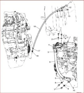
IMAGES PREVIEW OF THE MANUAL:
DESCRIPTION:
New Holland Tractor TS100A, TS110A, TS115A, TS125A TS130A, TS135A Service Manual
SAFETY RULES:
Generalities:
- Carefully follow specified repair and maintenance procedures.
- • Do not wear rings, wristwatches, jewels, unbuttoned or flapping clothing such as ties, torn clothes, scarves, open jackets or shirts with open zips which could get caught on moving parts. Use approved safety clothing such as anti-slipping footwear, gloves, safety goggles, helmets, etc.
- Wear safety glasses with side guards when cleaning parts using compressed air.
- Damaged or frayed wires and chains are unreliable. Do not use them for lifting or towing.
- Wear suitable protection such as approved eye protection, helmets, special clothing, gloves and footwear whenever welding. All persons standing in the vicinity of the welding process should wear approved eye protection. NEVER LOOK AT THE WELDING ARC IF YOUR EYES ARE NOT SUITABLY PROTECTED.
- Never carry out any repair on the machine if someone is sitting on the operator’s seat, except if they are qualified operators assisting in the operation to be carried out.
- Never operate the machine or use attachments from a place other than sitting at the operator’s seat or at the side of the machine when operating the fender switches.
- Never carry out any operation on the machine when the engine is running, except when specifically indicated. Stop the engine and ensure that all pressure is relieved from hydraulic circuits before removing caps, covers, valves, etc.
- All repair and maintenance operations should be carried out with the greatest care and attention.
- Disconnect the batteries and label all controls to warn that the tractor is being serviced. Block the machine and all equipment which should be raised.
- Never check or fill fuel tanks or batteries, nor use starting liquid if you are smoking or near open flames as such fluids are flammable.
- The fuel filling gun should always remain in contact with the filler neck. Maintain this contact until the fuel stops flowing into the tank to avoid possible sparks due to static electricity build-up.
- To transfer a failed tractor, use a trailer or a low loading platform trolley if available.
- To load and unload the machine from the transportation means, select a flat area providing a firm support to the trailer or truck wheels. Firmly tie the machine to the truck or trailer platform and block wheels as required by the transporter.
- Always use lifting equipment of appropriate capacity to lift or move heavy components.
- Chains should always be safely fastened. Ensure that fastening device is strong enough to hold the load foreseen. No persons should stand near the fastening point.
- The working area should be always kept CLEAN and DRY. Immediately clean any spillage of water or oil.
- Never use gasoline, diesel oil or other flammable liquids as cleaning agents. Use non-flammable non-toxic proprietary solvents.
- Do not pile up grease or oil soaked rags, as they constitute a great fire hazard. Always place them into a metal container.
TABLE OF CONTENTS:
New Holland Tractor TS100A, TS110A, TS115A, TS125A TS130A, TS135A Service Manual
GENERAL SECTION 00
General Information Chapter 1
Section Description Page
00 000 General Instructions 2
Health and Safety 5
Ecology and the Environment 13
Product Identification 14
International Symbols 17
General Dimensions 18
Vehicle Weights 22
Capacities 24
General Hardware Tightening Torques 25
SEPARATING THE TRACTOR SECTION 01
Separating front axle and front support Chapter 1
from the engine
Section Description Page
Torque Values 2
Special Tools 2
10 001 Separating Front Axle and Front Support from the Engine 3
10 001 Installing Front Axle and Front Support to the Engine 9
Front Axle to Front Support Shim Calculation 14
Separating Engine and Front Support from the Transmission Chapter 2
Section Description Page
Torque Values 2
Special Tools 2
Separating Engine and Front Support from the Transmission 4
Installing Engine and Front Support to the Transmission 11
Contents Continued:
604 55 151 06 –06–2005 ii
Separating Transmission, Engine and Front Support Chapter 3
from the Rear Axle
Section Description Page
Torque Values 2
Special Tools 2
Separating Transmission, Engine and Front Support from the Rear Axle 3
Installing Transmission, Engine and Front Support to the Rear Axle 8
Engine Removal Chapter 4
Section Description Page
Torque Values 2
Special Tools 2
Engine Removal 3
Engine Installation 12
Transmission Removal Chapter 5
Section Description Page
Torque Values 2
Special Tools 2
Transmission Removal 3
Transmission Installation 6
Cab Removal Chapter 6
Section Description Page
Torque Values (Tractors with Cab Suspension) 2
Torque Values (Tractors with Standard Cab) 3
Special Tools 3
90 150 Cab Removal 4
90 150 Cab Installation 13
ENGINE SECTION 10
Engine — 4 Cylinder Electronic Chapter 1
Section Description Page
10 000 General specifications 2
Assembly Clearances — Data 4
Torque wrench settings 7
Tools 13
Cooling system 14
Lubrication system 15
Lubrication system components 16
Engine overhaul 17
Contents Continued:
iii 604 55 151 06 –06–2005
Bushings 29
Assembly on the workbench 30
Fitting engine components 35
Checks, dimensions and repairs (cylinder liner block) 52
Checks, dimensions and repairs — crankshaft, bearings 54
Timing system 59
Bushings 60
Checks, dimensions and repairs — pistons 61
Connecting rod — piston assembly 70
Valves 72
Valve guides 73
Valve seats 73
Valve springs 75
Fitting the cylinder head 76
Fuel supply gear pump 79
CP3 high–pressure pump 80
Rail (pressure accumulator) 85
Pressure relief valve 86
Electro–injector 87
Pressure limiter for fuel return 88
Engine — 6 Cylinder Electronic Chapter 2
Section Description Page
10 000 General specifications 2
Assembly Clearances — Data 4
Torque wrench settings 8
Tools 13
Cooling system 14
Lubrication system 15
Camshaft timing operations 16
Fitting the cylinder head 17
Cylinder block repairs 19
Crankshaft 21
Timing system 24
Bushings 25
Checks, dimensions — connecting rod–piston assembly 26
Valves 28
Valve guides 28
Valve seats 28
Spindle — Rocker arms 30
Rail (pressure accumulator) 31
Contents Continued:
604 55 151 06 –06–2005 iv
Engine — 4 Cylinder Mechanical Chapter 3
Section Description Page
General specifications 2
Assembly Clearances — Data 4
Torque wrench settings 7
Tools 11
Mechanical Grid Heater Operation 11
Cooling system 12
Lubrication system 13
Lubrication system components 14
Engine overhaul with rotary mechanical pump 15
Disassembly at the bench 16
Assembly at the bench 29
Checks and measurements 51
Crankshaft 53
Timing system 58
Bushings 59
Checks, dimensions and repairs — connecting rod/piston assembly 60
Cylinder head 69
Valves 71
Valve guides 72
Valve seats 72
Valve springs 74
Fitting the cylinder head 74
Spindle — Rocker arms 75
Rotary fuel pump — disassembly, assembly and timing procedure 77
Engine — 6 Cylinder Mechanical Chapter 4
Section Description Page
General specifications 2
Assembly Clearances — Data 4
Torque wrench settings 7
Tools 11
Mechical Grid Heater Operation 11
Cooling system 12
Lubrication system 13
Camshaft timing operations 14
Fitting the cylinder head 15
Cylinder block repairs 16
Crankshaft 18
Contents Continued:
v 604 55 151 06 –06–2005
Timing system 21
Bushings 21
Checks, dimensions — connecting rod–piston assembly 22
Valves 25
Valve guides 25
Valve seats 25
Spindle — Rocker arms 26
Rotary fuel pump disassembly, assembly and timing procedure 28
Cooling Chapter 5
Section Description Page
Specifications 2
Torque Values 2
Description and Operation 3
Troubleshooting 7
Cooling System Drain 8
Cooling System Refill 9
10 406 Radiator Removal 9
10 406 Radiator Installation 12
Radiator Inspection and Repair 14
10 402 Thermostat Removal — Engines with Common Rail Fuel Injection 14
10 402 Thermostat Installation — Engines with Common Rail Fuel Injection 15
10 402 Thermostat Removal — Engines with Mechanical Fuel Injection 16
10 402 Thermostat Installation — Engines with Mechanical Fuel Injection 17
Thermostat Inspection 18
Coolant Temperature Sensor Removal — Engines with Common Rail Fuel Injection 19
Coolant Temperature Sensor Installation — Engines with Common Rail Fuel Injection 19
Coolant Temperature Sender Removal — Engines with Mechanical Fuel Injection 19
Coolant Temperature Sender Installation — Engines with Mechanical Fuel Injection 19
10 414 Viscous Fan Assembly Removal 20
10 414 Viscous Fan Assembly Installation 21
Fan Blade Removal 22
Fan Blade Installation 22
Fan Belt Removal 22
Fan Belt Installation 22
10 414 Spring–loaded Automatic Fan Belt Tensioner Removal 22
10 414 Spring–loaded Automatic Fan Belt Tensioner Installation 23
Fan Belt Tensioner Inspection and Repair 23
10 402 Coolant Pump Removal 23
10 402 Coolant Pump Installation 23
Contents Continued:
604 55 151 06 –06–2005 vi
Fuel Tank Removal Chapter 6
Section Description Page
10 216 Fuel Tank Removal 2
10 216 Fuel Tank Installation 3
Fuel Injection Pump —
4 Cylinder TS–A Delta Models (06–2005) with Delphi Pumps Chapter 7
Section Description Page
Specifications 1
Tightening Torques 1
Special Tools 1
Description and Operation 2
Pump Removal 4
Pump Installation 6
CLUTCHES SECTION 18
Clutches Chapter 1
Section Description Page
18 000 Specifications, Tightening Torques and Special Tools 1
Fault Finding 2
Description and Operation 4
18 110 Clutch Overhaul — Removal 5
Clutch Inspection and Repair 5
Hydraulic Release Bearing / Slave Cylinder Assembly Overhaul 6
TRANSMISSION SYSTEM SECTION 21
16 x 16 Transmission Chapter 1
Section Description Page
Specifications 2
Torque Values 3
Special Tools 7
Description And Operation 9
Fault Finding Diagrams 41
Transmission Disassembly/Assembly Information 50
Transmission Disassembly 52
Front Section Removal 53
Middle Section Removal 57
Rear Section Removal 59
Front Section Disassembly/Assembly 62
Middle Section Disassembly/Assembly 77
Contents Continued:
vii 604 55 151 06 –06–2005
Rear Section Disassembly/Assembly 85
Transmission Top Cover Overhaul 105
Transmission Control Valve Overhaul 107
Synchroniser Inspection 111
Transmission Housing Transfer Tubes Removal/Installation 112
Transmission Assembly 113
Forward/Reverse Synchroniser End–Float Adjustment 117
Adjustment of Forward/Reverse and Main (1–4/5–8) Synchronisers 122
High/Low Range Cable adjustment 123
Adjustment of the High/Low Synchroniser 124
24 x 24 Transmission Chapter 2
Section Description Page
Specifications 2
Torque Values 4
Special Tools 6
Description And Operation 8
Fault Finding 33
C1/C2 Clutch Housing Removal 36
C1/C2 Clutch Housing Disassembly 38
C1/C2 Clutch Components Inspection 46
C1/C2 Clutch Housing Assembly 46
C1/C2 Clutch Plate Set Adjustment 54
C1 Clutch Cluster Gear Shaft End Float Adjustment 55
C1/C2 Clutch Housing Installation 57
Lubrication Oil Control Valve Disassembly/assembly 60
Transmission Disassembly 61
Front Section Removal 63
Rear Section Removal 64
Middle Section Removal 66
Transmission Component Disassembly/Assembly 68
Front Section 72
Rear Section 73
Middle Section 76
Transmission Assembly 81
Middle Section Installation 81
Rear Section Installation 83
Front Section Installation 85
Output Shaft End Float Adjustments 89
Gearshift Cable Adjustments 91
Contents Continued:
604 55 151 06 –06–2005 viii
12 x 12 Transmission Chapter 3
Section Description Page
Specifications 2
Torque Values 3
Special Tools 5
Description And Operation 7
Fault Finding 19
Transmission Disassembly 21
Front Section Removal 24
Rear Section Removal 25
Middle Section Removal 27
Transmission Component Disassembly/Assembly 29
Front Section 32
Rear Section 34
Middle Section 37
Transmission Assembly 42
Middle Section Installation 42
Rear Section Installation 44
Front Section Installation 46
Output Shaft End Float Adjustment 51
Gearshift Cable Adjustments 53
Reduction Units Chapter 4
Section Description Page
21 000 Specifications 2
Sectional Views 2
Description and Operation 4
Fault Finding 7
Refer to the rear axle section for the removal of creeper components
DRIVE LINES SECTION 23
Drive Lines Chapter 1
Section Description Page
23 000 Specifications 2
Torque Values 3
Special Tools 4
Description and Operation 5
Fault Finding 12
23 101 Standard Front Axle Four Wheel Driveshaft Removal 13
23 101 Standard Front Axle Four Wheel Driveshaft Installation 14
Contents Continued:
ix 604 55 151 06 –06–2005
23 101 SuperSteer Front Axle Four Wheel Driveshaft Removal 16
23 101 SuperSteer Front Axle Four Wheel Driveshaft Installation 17
23 202 Four Wheel Drive Clutch Removal 18
23 202 Four Wheel Drive Multi–Wet Plate Clutch Disassembly 21
23 202 Four Wheel Drive Multi–Wet Plate Clutch Assembly/Adjustments 24
23 202 Four Wheel Drive Dog Clutch Disassembly 29
23 202 Four Wheel Drive Dog Clutch Assembly 31
23 202 Four Wheel Drive Clutch Installation 32
Four Wheel Driveshaft Oil Supply Manifold Removal 35
Four Wheel Driveshaft Oil Supply Manifold Installation 36
MECHANICAL FRONT AXLE SECTION 25
Mechanical Front Axle Chapter 1
Section Description Page
25 000 Specifications 2
Torque Values 4
Special Tools 6
Sectional Views 9
Description and Operation 9
Troubleshooting 12
25 100 Standard Axle Removal 13
25 100 Standard Axle Installation 16
Hub Cassette Seal Removal / Installation 19
Front Axle Overhaul — All Options 23
Multi–Wet Plate Clutch Differential Lock — Disassembly 29
Multi–Wet Plate Clutch Differential Lock — Assembly 33
Crown Wheel / Differential — Disassembly —
Multi–Wet Plate Clutch Differential Lock 35
Crown Wheel / Differential — Assembly / Adjustments
Multi–Wet Plate Clutch Differential Lock 38
Dog Clutch Differential Lock — Disassembly / Assembly 43
Crown Wheel / Differential — Disassembly / Assembly —
Dog Clutch Differential Lock 45
Pinion Shaft Removal — Standard Front Axle 47
Pinion Shaft Installation / Adjustments — Standard Front Axle 49
Pinion Shaft Removal — SuperSteer and Suspended Front Axle 56
Pinion Shaft Installation / Adjustments — SuperSteer and Suspended Front Axle 58
Crown Wheel Adjustments — Multi–Wet Plate Clutch Differential Lock 64
Differential Bearing Preload — Multi–Wet Plate Clutch Differential Lock 65
Crown Wheel Adjustments — Dog Clutch Differential Lock 66
Differential Bearing Preload — Dog Clutch Differential Lock 68
Limited Slip Self Locking Differential — Description and Operation 69
Limited Slip Self Locking Differential — Overhaul 70
Axle Assembly — All Options 73
Swivel Pin & Potentiometer — Removal / Installation 74
Stub Axle Adjustments 77
Checking the Alignment of Steering & Drive Wheels 79
Refer to Brake Section Of Repair Manual For Overhaul Of Front Axle Brakes Where
Fitted
Contents Continued:
604 55 151 06 –06–2005 x
Front Axle Suspension Chapter 2
Section Description Page
25 000 Specifications 2
Tightening Torques 2
Description and Operation 3
System Schematics 8
Suspended Front Axle Calibration Procedure 17
Fault Code Listing 20
Suspension Control Valve Assembly–Removal 22
Suspension Control Valve Assembly–Overhaul 22
Supersteer Front Axle Chapter 3
Section Description Page
Specifications 2
Torque Values 3
Special Tools 4
Description and Operation 5
25 100 33 SuperSteer Axle Removal 7
25 100 33 SuperSteer Axle Installation 10
Swivel Bearing Adjustment 14
MECHANICAL REAR WHEEL DRIVE (Rear Axle) SECTION 27
Mechanical Rear Wheel Drive Chapter 1
Section Description Page
27 000 Specifications 1
Torque Values 3
Special Tools 6
Sectional Views 9
Description and Operation 12
Troubleshooting 15
Rear Axle Disassembly 18
Rear Axle Assembly / Adjustments 29
Rear Pinion and Crown Wheel Adjustments 32
Hydraulic Pump Idler Gear Bearing Adjustment 44
Hydraulic Differential Lock Control Unit (Multi–Wet plate clutch) Inspection 50
Hydraulic Differential Lock Control Unit (Multi–Wet plate clutch) Disassembly 50
Hydraulic Differential Lock Control Unit (Multi–Wet plate clutch) Assembly/Adjustments 54
Final Drive Case (Left or Right Hand) Removal 60
Final Drive Case (Left or Right Hand) Installation 63
Drive Wheel Shaft Removal/Installation 66
Planetary Gear Set Removal/Installation 69
Contents Continued:
xi 604 55 151 06 –06–2005
50 Km/h Drive (17th Gear) Chapter 2
Section Description Page
27 000 Specifications 2
Torque Values 3
Special Tools 4
Sectional Views 5
Description And Operation 7
Fault Finding 10
50 Km/h Clutch (17th Gear) Removal 11
50 Km/h Clutch (17th Gear) Disassembly 17
50 Km/h Clutch (17th Gear) Assembly 20
50 Km/h Clutch (17th Gear) Installation 23
50 Km/h Solenoid Valve Block Removal 29
50 Km/h Solenoid Valve Block Disassembly/Assembly 30
50 Km/h Solenoid Valve Block Installation 30
Contents Continued:
604 55 151 06 –06–2005 xii
CONTENTS — VOLUME 2
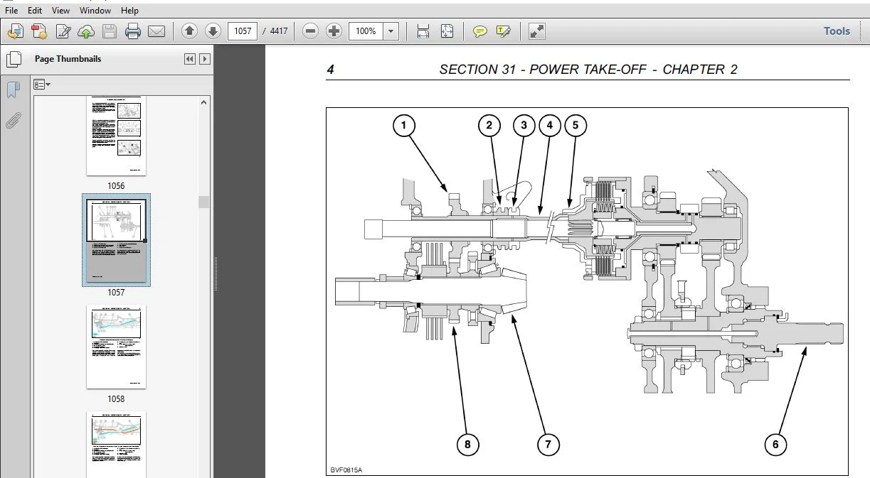
POWER TAKE–OFF SECTION 31
Shiftable Rear Power Take–Off Chapter 1
Section Description Page
31 000 Specifications 2
Special Tools 3
540/750/1000 RPM PTO Sectional View and Torque Values 4
540/1000 RPM PTO Sectional Views and Tightening Values 5
Description and Operation 6
PTO Functionality 12
Fault Finding 20
Power Take–Off (PTO) Removal 21
Power Take–Off (PTO) Installation 23
Power Take–Off (PTO) 540/750/1000 RPM Disassembly 25
Power Take–Off (PTO) 540/750/1000 RPM Assembly 33
2 Speed Shaft Change PTO — Initial PTO shaft set up
For tractors with Driveline Serial Number up to 009017242 only 41
For tractors with Driveline Serial Number from 009017243 only 43
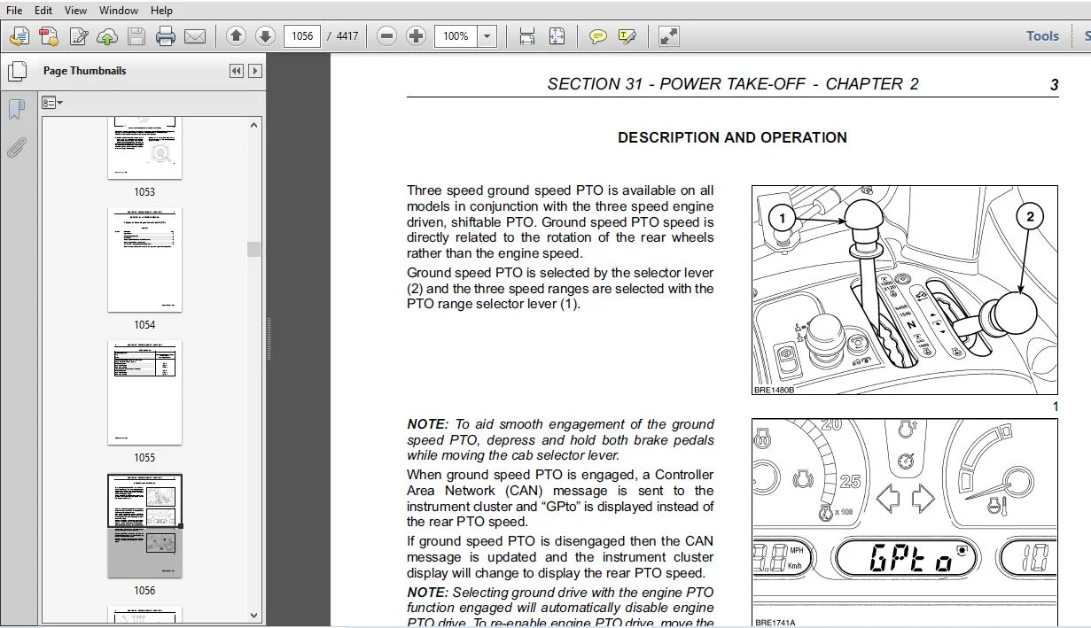
Ground Speed Power Take–Off (PTO) Chapter 2
Section Description Page
31 000 Specifications 2
Description and Operation 3
Fault Finding 7
Ground Speed PTO Selector Cable Adjustment 8
Ground Speed PTO Switch Adjustment 8
PTO Clutch Oil Supply Cut–Off Valve Adjustment 8
Refer to the rear axle section for the removal of ground speed PTO components
BRAKES SECTION 33
Tractor Brakes Chapter 1
Section Description Page
33 000 Specifications 2
Special Tools 3
Torque Values 4
Sectional Views 5
Description and Operation 7
Fault Finding 14
33 202 Rear Service Brake Piston (Left or Right Hand) Removal 16
Contents Continued:
xiii 604 55 151 06 –06–2005
Rear Service Brake Inspection 17
33 202 Rear Service Brake Piston (Left or Right Hand) Installation 18
Front Service Brake Valve Removal 20
Front Service Brake Valve Installation 22
33 204 Front Service Brake (Left or Right Hand) Disassembly 24
33 204 Front Service Brake (Left or Right Hand) Assembly 29
33 202 Hydraulic Brake Master Cylinder Removal (All Models) 34
33 202 Hydraulic Brake Master Cylinder Installation (All Models) 36
33 202 Hydraulic Brake System Air Bleeding 38
Front Service Brake Valve Removal — Models with integrated front lift 42
Front Service Brake Valve Installation — Models with integrated front lift 44
Brake Pedal Switch Removal 46
Brake Pedal Switch Installation 47
Brake Pedal Linkage Adjustment 48
Brake Pedal Switch Adjustment 49
33 110 Parking Brake Removal 49
33 110 Parking Brake Disassembly 50
33 110 Parking Brake Assembly 51
33 110 Parking Brake Installation 53
Parking Brake Cable Adjustment 55
Additional Information — Brake Overhaul 56
Air Trailer Brakes Chapter 2
Section Description Page
33 000 Specifications 1
Tightening Torques 2
Description and Operation 3
Fault Finding 13
33 000 Removal and Installation 15
33 000 Overhaul 21
Pressure Testing 31
Contents Continued:
604 55 151 06 –06–2005 xiv
HYDRAULIC SYSTEMS SECTION 35
Introduction and Hydraulic Circuits Chapter 1
Section Description Page
35 000 Introduction and Circuit Identification 2
Variable Displacement Pump High Pressure Hydraulic Circuits 7
Fixed Displacement Pump High Pressure Hydraulic Circuit 23
Low Pressure Hydraulic Circuits
Tractors with 16 x 16 Transmission 28
Tractors with 24 x 24 Transmission 37
Tractors with 12 x 12 Transmission 43
General Hydraulic Fault Finding 47
Initial Fault Finding Check 47
Transmission Low Pressure Warning Light ‘ON’ 51
Charge Pressure Light 51
Intake Filter Restriction Warning Light 51
Power Steering 52
Trailer Brakes 52
Hydraulic Lift 53
Remote Control Valves 54
Variable Flow Hydraulic Pump Assembly Chapter 2
Section Description Page
35 000 Specifications 2
Tightening Torques 3
Description and Operation 4
Hydraulic Circuit Operation 12
Generating Low Pressure Standby 14
Regulating Low Pressure Standby 16
High Pressure Circuit High Demand 18
High Pressure Circuit Low Demand 20
Limiting Maximum System Pressure 22
Low Pressure Regulating valve operation 24
Fault Finding 27
Initial Fault Finding Check 27
Transmission Low Pressure Warning Light ‘ON’ 28
Charge Pressure Light 29
Intake Filter Restriction Warning Light 29
Power Steering 30
Trailer Brakes 30
Contents Continued:
xv 604 55 151 06 –06–2005
Hydraulic Lift 31
Remote Control Valves 32
Pump Pressure and Flow Testing 34
35 106 Overhaul 35
Steering Pump Overhaul 36
Pressure and Flow Compensating Valve 38
Pump Removal and Installation 40
Charge Pump Overhaul 44
Variable Flow Piston Pump Overhaul 46
Hydraulic Lift Assembly with Electronic Draft Control Chapter 3
Section Description Page
35 000 Specifications 2
Special Tools 2
Tightening Torques 3
Description and Operation 4
Principal of Draft Control 4
Components 7
Operator Controls 9
Operation of Draft Control 13
Hydraulic Operation of Lift Control Valve 16
Electronic Draft Control Calibration 26
Electronic Draft Control Error Codes 27
Overhaul
35 138 Electronic Draft Control Valve — Removal 29
35 138 Electronic Draft Control Valve — Installation 30
35 138 Disassembly 31
35 130 Load Sensing Pin Replacement 36
Mechanical Rear Hydraulic Lift Chapter 4
Section Description Page
Specifications 2
Torque Values 5
Special Tools 7
Description and Operation 8
Troubleshooting 18
35 110 30 Mechanical Rear Hydraulic Lift Removal 20
35 110 30 Mechanical Rear Hydraulic Lift Installation 23
Mechanical Rear Hydraulic Lift Disassembly 26
Mechanical Rear Hydraulic Lift Assembly 30
Mechanical Rear Hydraulic Lift Adjustments 36
Mechanical Rear Hydraulic Lift External Cable Adjustments 42
Contents Continued:
604 55 151 06 –06–2005 xvi
Lift–O–Matic Upper Stroke Height Limit Adjuster 45
Mechanical Rear Hydraulic Lift Control Valve Disassembly 46
Mechanical Rear Hydraulic Lift Control Valve Assembly 51
Fixed Displacement Gear Pump Chapter 5
Section Description Page
35 000 Specifications 1
Torque Values 2
Description and Operation 3
Troubleshooting See Chapter 9
Hydraulic Lift System Oil Pump Removal 5
Hydraulic Lift System Oil Pump Installation 9
Steering / Low Pressure Oil Pump Removal 12
Steering / Low Pressure Oil Pump Installation 14
Hydraulic Lift System Oil Pump Disassembly / Assembly 16
Steering / Low Pressure Oil Pump Disassembly / Assembly 18
Hydraulic Oil Pump Inspection 20
Trailer Brake Auxiliary Valves Chapter 6
Section Description Page
35 000 Specifications 2
Torques 2
Description and Operation 3
33 220 Italian Trailer Brakes 10
Trailer Brake Valve Removal 21
Trailer Brake Valve Installation 22
Italian Trailer Brake Solenoid Valve Block Removal 23
Italian Trailer Brake Solenoid Valve Block Installation 23
Mechanical Remote Control Valves Chapter 7
Section Description Page
Special Tools 2
Specifications 2
Torque Values 2
Fault Finding 3
Description and Operation — Mechanical Remote Control Valves 4
Oil Flow In Neutral 10
Oil Flow in Raising (Cylinder Extend) 12
Oil Flow in Lowering (Cylinder Retract) 14
Oil Flow in Float 16
Operation of Detent Pressure Regulating Valve 18
Contents Continued:
xvii 604 55 151 06 –06–2005
Operation of Two or More Control Valves Simultaneously 21
Remote Control Valve Removal 23
Remote Control Valve Installation 26
Remote Control Valve Cable Adjustment 29
Remote Control Valve Disassembly 30
Remote Control Valve Assembly 36
Electronic Remote Control Valves Chapter 8
Section Description Page
35 000 Special Tools 2
Specifications 2
Tightening Torques 2
Fault Finding 3
Electro–Hydraulic Remote Valve Fault Code list 4
Description and Operation — Electro–Hydraulic Remote Valves 7
Re–Calibrating Remote Valve Levers 23
Oil Flow In Neutral 25
Oil Flow in Raising (Cylinder Extend) 27
Oil Flow in Lowering (Cylinder Retract) 29
Oil Flow in Float 31
Operation of Two or More Control Valves Simultaneously 33
Overhaul — Electro–Hydraulic Remote Valves 35
Electro–Hydraulic Remote Valves Number Programming 36
Electro–Hydraulic Remote Valves Removal and Installation 38
Electro–Hydraulic Remote Valve Disassembly 39
Hydraulic Pressure Testing Chapter 9
Section Description Page
35 000 Introduction 3
Special Tools 4
Specifications 5
Initial Fault Finding 7
Transmission / Steering Low Pressure Warning Symbol / Light — Displayed
(Variable Displacement Closed Centre Systems) 8
Transmission Low Pressure Warning Symbol / Light — Displayed
(Fixed Displacement Closed Centre Systems) 10
Charge Pressure Warning Symbol / Light — Displayed
(Variable Displacement Closed Centre Systems) 12
Intake Oil Filter Warning Symbol / Light On 14
Power Steering Not Working or Working Incorrectly 16
Contents Continued:
604 55 151 06 –06–2005 xviii
Trailer Brakes Not Working 16
Electronic Draft Control Not Working Correctly 17
Pump Pressure and Flow Testing 19
Low Pressure Standby 19
High Pressure Standby 20
Charge Pressure Test 21
Variable Flow Piston Pump Flow Test 22
Hydraulic Oil Pump Air Ingress Test 22
Lift Ram Pressure Test 24
Steering / Low Pressure Hydraulic Pump Test 25
Steering Test 25
Steering Circuit Pressure Test 25
Steering Relief Valve Pressure Test 26
Low Pressure System Test 27
Low Pressure Component Tests 28
50 Kph Clutch Pressure Test 30
Low Pressure Component Leak Test (Variable Displacement Closed Centre Systems) 31
Fixed Displacement Pump — Lift Pressure Regulating Valve 32
16 x 16 Transmission Pressure Testing 33
24 x 24 Transmission Pressure Testing 41
Cooler By–pass Valve — Lubrication Pressure 46
Trailer Brake Testing and Troubleshooting 46
Trailer Braking System Pressure Test (All Models) 46
Trailer Brake System Leak Test (All Models) 47
Trailer Brake Valve Electro–Hydraulic Operation Diagram (Italy Only) 48
Trailer Brake Disengagement Pressure Test (Italy Only) 49
Parking Brake Engagement Test (Italy Only) 50
Trailer Brake Circuit Safety Switch Test (Italy Only) 50
External Lift Rams Chapter 10
Section Description Page
35 000 Specifications 2
Sectional Views 2
Description and Operation 4
35 116 Removal 4
Disassembly 5
Reassembly 6
Installation 6
Contents Continued:
xix 604 55 151 06 –06–2005
Front Loader Chapter 11
Section Description Page
35 000 Specifications, Tightening Torques and Special Tools 1
Installation Instructions 12
Hydraulics — Operation 25
Electrical Wiring Diagrams 63
Loader and Hydraulic System Overhaul 71
Faultfinding 82
Mid Mount Remote Valves Chapter 12
Section Description Page
35 000 Specifications 2
Torque Values 3
Description and Operation 4
Mid Mount Valve Removal 12
Mid Mount Valve Disassembly 12
Mid Mount Valve Overhaul 13
Mid Mount Valve Installation 16
Third Mid Mount Valve 17
Description and Operation 17
Removal 19
Disassembly 19
Re–assembly 20
Hydraulic Front Lift and Power Take–Off (PTO) Chapter 13
Section Description Page
35 000 Specifications 2
Torque Values 2
Special Tools 6
Sectional Views 7
Description and Operation 9
Fault Finding 13
Hydraulic Front Lift Removal 14
Hydraulic Front Lift Disassembly 16
Hydraulic Front Lift Assembly 17
Hydraulic Front Lift Installation 19
Hydraulic Front Lift Ram Removal 20
Hydraulic Front Lift Ram Installation 22
Front PTO Control Housing Removal 24
Front PTO Control Housing Disassembly 29
Front PTO Control Housing Assembly 32
Contents Continued:
604 55 151 06 –06–2005 xx
Front PTO Control Housing Installation 35
Front PTO Clutch Removal 38
Front PTO Clutch Disassembly 39
Front PTO Clutch Assembly 42
Front PTO Clutch Installation 46
Front PTO Reduction Gearbox Removal 47
Front PTO Reduction Gearbox Disassembly 49
Front PTO Reduction Gearbox Assembly 51
Front PTO Reduction Gearbox Installation 54
TS–A Delta Models Hydraulic Circuits Chapter 14
Section Description Page
35 000 Introduction and Circuit Identification 2
Fixed Displacement Pump High Pressure Hydraulic Circuit 9
Low Pressure Hydraulic Circuits
Tractors with 12 x 12Transmission 14
Tractors with 16 x 16Transmission 19
Tractors with 24 x 24Transmission 29
General Hydraulic Fault Finding 35
Initial Fault Finding Check 35
Transmission Low Pressure Warning Light ‘ON’ 36
Intake Filter Restriction Warning Light 36
Power Steering 37
Trailer Brakes 37
Hydraulic Lift 38
Remote Control Valves 38
TS–A Delta — Open centre system remote control valves Chapter 15
Section Description Page
Data — Tools 1
Tightening Torques 2
Cross–sectional views 3
Description and Operation 4
Mechanical Remote Valve Disassembly 11
Mechanical Remote Valve Installation 14
Mechanical Remote Valve Cable Adjustment 17
Mechanical Remote Valve Slice Disassembly 18
Troubleshooting See Chapter14
Contents Continued:
xxi 604 55 151 06 –06–2005
TS–A Delta Mid Mount Remote Valves Chapter 16
Section Description Page
Specifications 2
Torque Values 2
Description and Operation 3
Mid Mount Valve Removal 10
Mid Mount Valve Disassembly 10
Mid Mount Valve Overhaul 12
Mid Mount Valve Installation 15
Third Mid Mount Valve 17
Description and Operation 17
Removal 19
Disassembly 19
Re–assembly 19
Integrated Hydraulic Front Lift and Power Take–Off (PTO)
(All Models from 06–2005) Chapter 17
Section Description Page
Section Description Page
Specifications 2
Torque Values 2
Special Tools 5
Sectional Views 6
Description and Operation — Front Lift 8
Description and Operation — Power Take Off 11
Fault Finding 14
Hydraulic Front Lift Removal 15
Hydraulic Front Lift Disassembly 16
Front PTO Control Housing Removal 17
Front PTO Control Housing Disassembly 21
Front PTO Control Housing Assembly 24
Front PTO Control Housing Installation 27
Front PTO Clutch Removal 31
Front PTO Clutch Disassembly 32
Front PTO Clutch Assembly 35
Front PTO Clutch Installation 39
Front PTO Reduction Gearbox Removal 40
Front PTO Reduction Gearbox Disassembly 42
Front PTO Reduction Gearbox Assembly 44
Front PTO Reduction Gearbox Installation 47
Contents Continued:
604 55 151 06 –06–2005 xxii
STEERING SYSTEMS SECTION 41
Hydrostatic Steering Systems Chapter 1
Section Description Page
41 000 Specifications 2
Tightening Torques 3
Special Tools 4
Description and Operation 5
Fault Finding 9
System Testing 10
41 204 Steering Motor — Removal and Installation 15
Steering Motor Overhaul 16
Steering Column — Removal and installation 23
41 216 Two Wheel Drive Steering Cylinder — Removal and Installation 25
Two Wheel Drive Steering Cylinder — Overhaul 26
Four Wheel Drive Steering Cylinder — Removal and Installation 27
Four Wheel Drive Steering Cylinder — Overhaul 28
Fast Steer System Chapter 2
Section Description Page
41 000 Specifications 2
Tightening Torques 3
Description and Operation 4
Fast Steer Valve Components 7
Fast Steer Hydraulic Operation 8
Operating and Monitoring System 8
Fast Steer Hydraulic Circuit 10
Fast Steer Valve Removal 13
Fast Steer Valve Disassembly 13
Fast Steer Valve Inspection 14
Fast Steer Valve Re–Assembly 15
Fast Steer Valve Installation 15
Steering Column Removal and Installation 16
Fast Steer Error Codes 18
Fast Steer H routines 19
Fast Steer Wiring 24
Contents Continued:
xxiii 604 55 151 06 –06–2005
FRONT AXLE AND WHEELS SECTION 44
2 Wheel Drive Front Axle Chapter 1
Section Description Page
44 000 Specifications 2
Tightening Torques 3
Special Tools 4
Troubleshooting 4
Description and Operation 5
Sectional Views 6
44 101 Front Axle
Removal 7
Installation 9
Front Wheel Hub and Spindle Assembly 10
Removal 11
Overhaul 12
Installation 12
Spindle Assembly
Removal 13
Overhaul 14
Installation 15
Front Wheel Settings
44511 Wheel Camber Tests 16
Track Width Adjustment 16
Axle Centre Beam and Front Support
Removal 17
Overhaul 17
Installation 18
44 511 Front Wheel Toe–in 19
Contents Continued:
604 55 151 06 –06–2005 xxiv
CONTENTS — VOLUME 3
AUXILIARY UNITS SECTION 50
Air Conditioning Chapter 1
Section Description Page
50 000 Specifications 2
Tightening Torques 2
Special Tools 2
Safety Precautions 3
Description and Operation 4
Fault Finding and System Testing 15
Leak Testing, Charging, Discharging and System Flushing 32
Flushing the System 34
Evacuating the System 35
Charging the System 36
Component Overhaul (excluding compressor) 37
50 200 Compressor Removal and Installation 46
50 200 Compressor Overhaul 46
ELECTRICAL SYSTEM SECTION 55
Electrical Introduction Chapter 1
Section Description Page
55 100 Specifications 1
Electrical System and Fuses Description 2
Fuses and Relays 5
Controllers 17
Diagnostic Connectors 19
System Precautions For Battery Charging and Welding 20
Temporary Wiring Repair 21
System Diagrams 23
Contents Continued:
xxv 604 55 151 06 –06–2005
Electronic Instrument Cluster Chapter 2
Section Description Page
55 000 Introduction 2
Senders, Sensors & Switches 10
Error Codes 22
Enhanced Keypad and Performance Monitor 28
Programming the Displays 32
Starting System Chapter 3
Section Description Page
55 000 Specifications 1
Tightening Torques 1
Description and Operation 2
Fault Finding 5
System Testing 7
55 201 Removal and Installation 8
Overhaul 9
Bench Tests 11
Charging System Chapter 4
Section Description Page
55 000 Specifications 1
Tightening Torques 1
Description and Operation 2
Fault Finding 5
55 301 Removal, Installation and Overhaul 11
Battery Chapter 5
Section Description Page
55 000 Specifications 1
Description and Operation 1
55 300 Removal and Installation 2
Battery Maintenance and Testing 3
Battery Charging 4
Common Causes of Battery Failure 6
Contents Continued:
604 55 151 06 –06–2005 xxvi
Wiring Diagrams Chapter 6
Description Page
Wiring diagram circuit descriptions (All Models) 1
How to use the linear wiring diagrams 2
Symbols 4
Component identification and wiring diagram location key 5
Wiring Diagrams:
16×16 Transmission, W/Cab, W/Electronic Engine 13
16×16 Transmission, W/Cab, W/Mechanical Engine 71
24×24 Transmission, W/Cab, W/Electronic Engine 129
24×24 Transmission, W/Cab, W/Mechanical Engine 187
16×16 Transmission, L/Cab, W/Electronic Engine 245
16×16 Transmission, L/Cab, W/Mechanical Engine 303
24×24 Transmission, L/Cab, W/Electronic Engine 361
24×24 Transmission, L/Cab, W/Mechanical Engine 419
12×12 Transmission, W/Cab, W/Mechanical Engine 477
12×12 Transmission, L/Cab, W/Mechanical Engine 535
16×16 Transmission, W/Cab, W/Electronic Engine, W/EHR’s 593
Wire identification key 652
CONTENTS — VOLUME 4
ELECTRICAL SYSTEM SECTION 55
Connectors and Harnesses Chapter 7
Section Description Page
55 000 Wiring Harnesses 2
Main Connectors 3
Wire Identification and colour coding 4
Lighting Harness 5
Front Main 4 Cylinder Mechanical (Engine) Harness 9
Front Main 6 Cylinder Electronic (Engine) Harness 15
Front Electrical (Engine) Harness (with Electronic engine only) 21
Rear Main 16×16 (Transmission) Harness, 26
Rear Main 24×24 (Transmission) Harness, 35
Cab Main 16×16 / 24×24 Harness 43
Cab Switch Panel Harness (16×16 and 24×24) 61
Cab Switch Panel Harness (12×12) 65
Electronic Remotes Harness 69
Fender Harness 74
Cab Roof Harness 78
Cab Main 12×12 Harness 86
Rear Main 12×12 (Transmission) Harness, 97
Less Cab Main 16×16 & 24×24 Harness 102
Less Cab Main 12×12 Harness 117
Cab Roof Harness — Low Profile Cab (from 06–2005) 127
Contents Continued:
xxvii 604 55 151 06 –06–2005
Calibration Procedures Chapter 8
Section Description Page
55 100 Set Up Procedures 1
Calibration Error Codes (’U’ Codes) 3
16×16 Transmission — Clutch and Synchroniser Calibration 5
16×16 Transmission — Manual Adjustment of C3/C4 Clutches 9
24×24 Transmission — Clutch and Synchroniser Calibration 11
Electronic Draft Control — Calibration of Lift Lever/Arm Potentiometers 14
Electronic Draft Control — Calibration of EDC Valve Solenoids 16
Ground Speed Display Calibration 18
Suspended Front Axle Calibration 22
Electro–Hydraulic Remote Valve Lever Calibration 24
Electro–Hydraulic Remote Valve Renumbering procedure 26
P T O Torque Sensor Calibration 28
P T O Clutch Calibration 30
Steering Angle Calibration 32
Fault Codes Chapter 9
Section Description Page
55 000 Introduction 2
Special Tools 3
Wiring Harness Repairs 3
Digital Multi–Meter — Basic Operation 6
Electrical Test Procedures 9
Circuit Components — Basic Description 12
Controller Area Network (CAN) System 22
Fault Code Displays 23
H–Menu Diagnostic Mode 24
Fault Code Lists 25
Fault Code Charts
U–Codes 45
0001–1000 (General Fault Codes) 59
1001–2000 (Electronic Draft Control) 73
2001–3000 (Transmission) 207
Contents Continued:
604 55 151 06 –06–2005 xxviii
CONTENTS — VOLUME 5
ELECTRICAL SYSTEM SECTION 55
Fault Codes Chapter 9
3001–4000 (Engine) 423
5001–6000 (Rear Power Take–off) 763
6001–7000 (Four Wheel Drive) 813
7001–8000 (Differential Lock) 829
8001–9000 (Front Power Take–off) 855
9001–10000 (Front HPL) 877
10001–11000 (Front Axle Suspension) 885
14001–15000 (Analog Digital Instrument Cluster) 909
4001–5000 (Electro–Hydraulic Remotes (EHR’s)) 987
Additional Fault Code Charts Chapter 9a
Section Description Page
U–Codes 3
1001–2000 (Electronic Draft Control) 6
2001–3000 (Transmission) 11
3001–4000 (Engine) 61
5001–6000 (Rear Power Take–off) 70
8001–9000 (Front Power Take–off) 76
10001–11000 (Front Axle Suspension) 78
14001–15000 (Analog Digital Instrument Cluster) 80
15001–16000 (Fast Steer System) 85
Diagnostic ’H’ Routines Chapter 10
Section Description Page
55 000 Introduction 2
HA/HB Controller H Routines 9
DA/DB Controller H Routines 35
JA Controller H Routines 87
DD Controller (Options) H Routines 93
GA Controller H Routines 127
Electrical Introduction TS–A Delta Models (06–2005) Chapter 11
Section Description Page
55 100 Specifications 1
Electrical System and Fuses Description 2
Fuses and Relays 4
Controllers 17
Diagnostic Connectors 19
System Precautions For Battery Charging and Welding 20
Temporary Wiring Repair 21
PLEASE NOTE:
- This is the SAME manual used by the dealers to troubleshoot any faults in your vehicle. This can be yours in 2 minutes after the payment is made.
- Contact us at [email protected] should you have any queries before your purchase or that you need any other service / repair / parts operators manual.
Henrik Ronin –
got what i wanted got what i needed, thank you