Nichiyu FB-70 Series FB 10Р,14Р,15Р,18Р 20Р,25Р,28Р,З0Р Troubleshooting Manual PDF
$26.95
Nichiyu Forklift FB-70 Series FB 10Р,14Р,15Р,18Р 20Р,25Р,28Р,З0Р Troubleshooting Manual – PDF DOWNLOAD
Description
Nichiyu Forklift FB-70 Series FB 10Р,14Р,15Р,18Р 20Р,25Р,28Р,З0Р Troubleshooting Manual – PDF DOWNLOAD
FILE DETAILS:
Nichiyu Forklift FB-70 Series FB 10Р,14Р,15Р,18Р 20Р,25Р,28Р,З0Р Troubleshooting Manual – PDF DOWNLOAD
Language : English
Pages : 127
Downloadable : Yes
File Type : PDF
IMAGES PREVIEW OF THE MANUAL:
TABLE OF CONTENTS:
Nichiyu Forklift FB-70 Series FB 10Р,14Р,15Р,18Р 20Р,25Р,28Р,З0Р Troubleshooting Manual – PDF DOWNLOAD
FB70 01W2201 1
CONTENTS 2
1 Overview of SICOS – AC ( AC control) 4
1 1 Why change to AC now? 4
1 2 Features of SICOS – AC 6
1 3 Comparison of DC and AC 7
1 4 Types of motor 15
1 5 Features of AC motors 15
1 6 Speed control of AC motor 15
1 7 Induction motors 16
1 7 1 Principles of rotation 16
1 7 2 Rotating megnetic field 19
1 8 Inverter principles and acceleration/decceleration characteristics 21
1 8 1 Inverter construction 21
1 8 2 Inverter principles 21
1 8 3 Switching of rotation direction 25
2 Adjustments of SICOS – AC 26
2 1 Explanation of the monitor display 26
2 1 1 Indicator panel 26
2 1 2 Indication of display 27
2 1 3 Function of display 28
2 1 4 Various kinds of mode selection 33
2 2Explanation of the MPU board 39
2 2 1 Basic control board construction 39
2 2 2 Travel/ Hydraulic board 40
2 2 3 Display board 40
2 2 4 Rotary switch on the Travel/ Hydraulic board 41
2 2 5 Rotary switch on the Display board 42
2 2 6 Adjustment Standards List for FB 70 – series 43
2 3 SICOS – AC check and adjustment 44
2 3 1 Chasis insulation check 44
2 3 2 Battery voltage adjustment 45
2 3 3 Current detector check 46
2 3 4 Forklift model setting chack and adjustment 48
2 3 5 Safety circuit for control (contactor tripping) check 49
2 3 6 Hydraulic setting chack and adjustment 50
2 3 7 Descending regeneration check 50
2 3 8 Switch back (plugging/ regenerative) braking force adjustment 51
2 3 9 Regenerative braking force check and adjustment 52
2 3 10 Safety monitor symbol check and adjustment 53
2 3 11 Display language check and adjustment 54
2 3 12 Optional setting chack and adjustment 55
2 3 13 View and brightness of display adjustment 56
2 3 14 Hour meter working check 56
2 3 15 Auto power off function working check 56
2 3 16 battery electrolyte level working check 57
2 3 17 Turn signla lamp working check 57
2 3 18 Hydraulic oil level (optional) working check 58
2 3 19 Brake oil level working check 58
2 3 20 Overload (optional) working check 59
2 3 21 Travel inhibitor (optional) working check 59
2 3 22 Cooling fan worling check 59
2 3 23 Lift interrupt (optional) working check 60
2 3 24 Turning speed reduction (optional) adjustment and working check 61
2 3 25 Seat switch (optional) working check 62
2 3 26 Bult – in charger(optional) working check 63
3 Troubleshooting 64
3 1 Self diagnosis function 64
3 1 1 Display 64
3 1 2 Error massages and Display conditions 66
3 2 Error history memory 68
3 2 1 Error history memory 1 68
3 2 2 Error history memory 2 69
3 2 3 Clearing the error history memory (memory initialization) 71
3 3 I/O Check 72
3 3 1 I/O Check mode display method 72
3 3 2 I/O port table 74
4 Wiring and control unit layout 80
4 1 FB-70 System wiring 80
4 1 1 FB10 – 28-70 80
4 1 2 FB 30-70 81
4 2 FB-70 Body wiring 82
4 2 1 FB10-28-70 82
4 2 2 FB30-70 83
4 3 FB-70 Body Harness 84
4 3 1 FB10- 18-70 (Std/CS/FCS/RP/DRP) 84
4 3 2 FB10 – 18-70 (EEC) 85
4 3 3 FB20 – 20-70 (Std/CS/FCS/RP/DRP) 86
4 3 4 FB20 – 28-70 (EEC) 87
4 3 5 FB30 – 70 (Std/CS/FCS/RP/DRP) 88
4 3 6 FB30 – 70 (EEC) 89
4 4 FB-70 CU wiring 90
4 5 FB-70 CU wiring 91
4 5 1 CU harness (1) 91
4 5 2 CU harness (2) 92
4 6 FB-70 Control unit 93
4 6 1 FB10 -28-70 93
4 6 2 FB30-70 94
4 6 3 FB10 – 25-U70 95
4 7 FB-70 BC wiring 96
4 8 FB-70 Charger harness 97
4 8 1 Charger harness (1) 97
4 8 2 Charger harness (2) 98
4 9 FB-70 Wiring, revolving light 99
4 9 1 Key switch interlock 99
4 9 2 Forward/backward directional interlock 100
4 9 3 Backward directional interlock 101
4 10 FB-70 Wiring, working lamp 102
4 11 FB-70 Wiring, chime 103
4 11 1 Forward/backward chime 103
4 11 2 Forward chime 104
4 11 3 Backward chime 105
4 12 FB-70 Wiring, license 106
4 12 1 Large truck inspections, new small truck inspections 106
4 13 FB-70 Wiring, load sensor 107
4 13 1 Analog type 107
4 13 2 Digital type 108
4 14 FB-70 Wiring, lift limit 109
4 14 1 Lift limit for 1st stage 109
4 14 2 Lift limit for 2nd stages 110
4 15 FB-70 Wiring, seat heater 111
4 16 FB-70 Wiring, rear lamp 112
4 17 FB-70 Wiring, FS 113
4 18 FB-70 Wiring, wiper 114
4 18 1 Wiper 114
4 18 2 Lower wiper 115
5 Reference 116
5 1 MPU board connectors 116
5 1 1 Pin arrangement of housing 116
5 1 2 Name of parts 116
5 1 3 Installation of terminals into housing 117
5 1 4 How to extract terminals 118
5 1 5 Crimp tools (manufactured bu AMP) 119
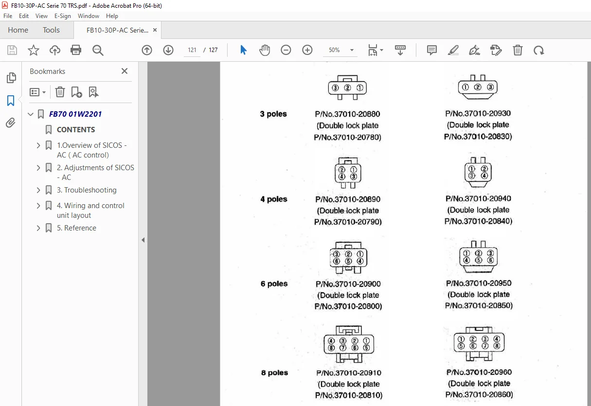
5 2 Water resistant connector 120
5 2 1 Water resisitant connectors 120
5 2 2 Water resistant connectors (other than those described above) 120
S.V 06/24