
Nichiyu FB 75 Series CAN-BUS Workshop Manual – FB10P to FB30P Electric Forklift Service & Repair PDF
Original price was: $39.95.$24.95Current price is: $24.95.
Complete Nichiyu FB 75 Series CAN-BUS control workshop manual covering FB10P, FB14P, FB15P, FB18P, FB20P, FB25P, FB28P and FB30P electric forklifts. Full disassembly, assembly, inspection, adjustment, troubleshooting and service data. Instant PDF download.
Description
Nichiyu FB 75 Series CAN-BUS Workshop Manual – FB10P through FB30P
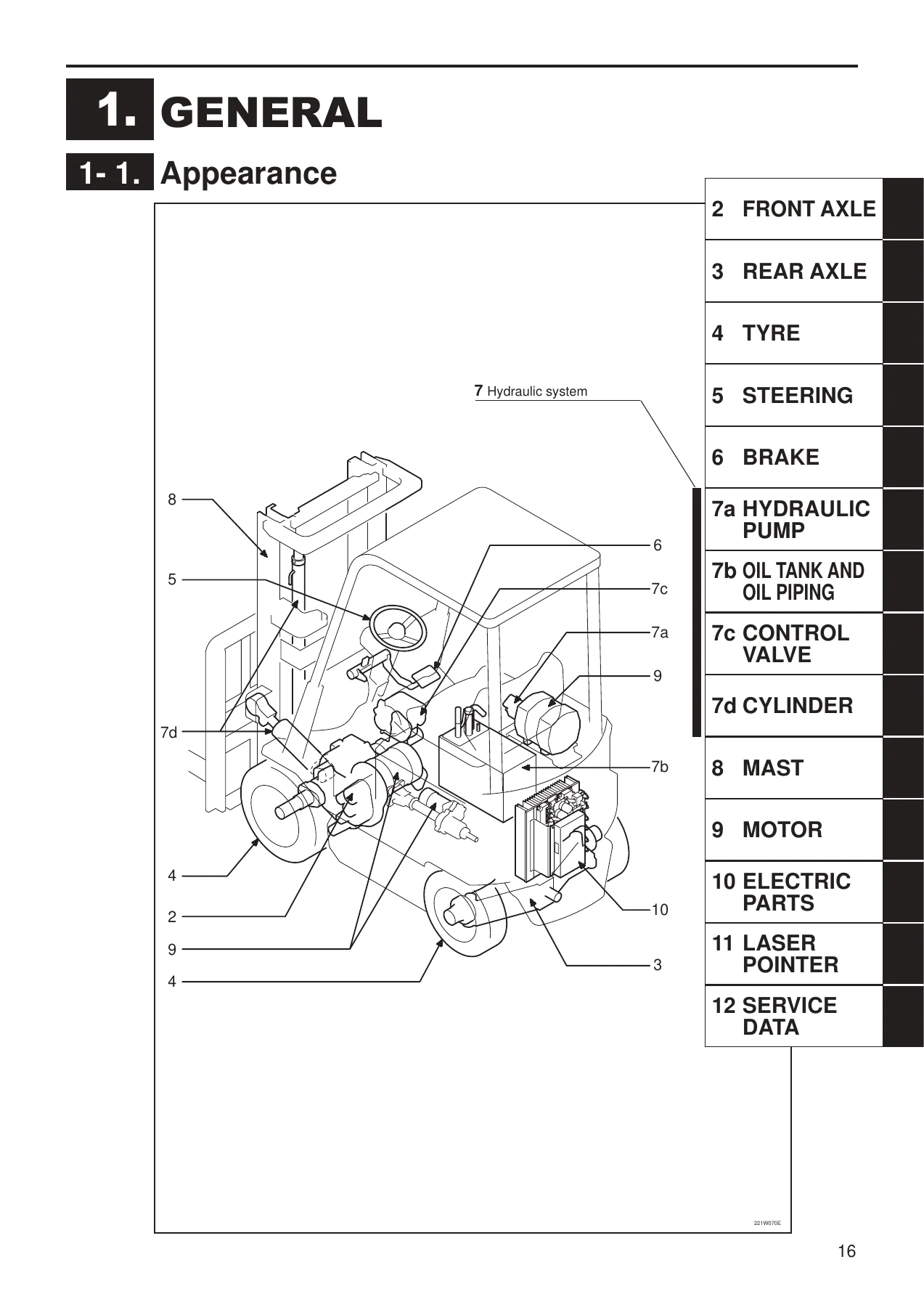
This is the full workshop manual for the Nichiyu FB 75 series electric forklift trucks equipped with CAN-BUS control. It covers the FB10P, FB14P, FB15P, FB18P, FB20P, FB25P, FB28P and FB30P models, and also documents the earlier IGBT and FET control variants where procedures differ. Whether you are servicing a single truck in a small fleet or running a workshop that maintains several FB-series machines, this manual gives you the manufacturer’s own disassembly, assembly, inspection and adjustment procedures rather than a generic third-party summary.
The manual was prepared by Nippon Yusoki Co., Ltd for use by trained maintenance personnel, and it assumes access to standard workshop tools and facilities for Nichiyu electric lift trucks. Every system on the truck is covered — from the front drive axle and rear steering axle through the brake system, hydraulic pump, control valve, cylinders, mast, traction and hydraulic motors, and the complete electrical architecture including the CAN-BUS control unit, MPU board, EPS controller and built-in charger.
File Details
- Manual type: Workshop Manual (service, repair and maintenance)
- Brand: Nichiyu (Nippon Yusoki Co., Ltd)
- Series: FB 75 series electric forklift trucks
- Models covered: FB10P, FB14P, FB15P, FB18P, FB20P, FB25P, FB28P, FB30P (plus -U high-speed variants)
- Control systems documented: CAN-BUS control, IGBT control, FET control
- Language: English
- Page count: 230 pages
- File format: PDF
- Edition: Second edition, September 2008 (first printing December 2003)
Chapters Covered
- General — appearance, specifications
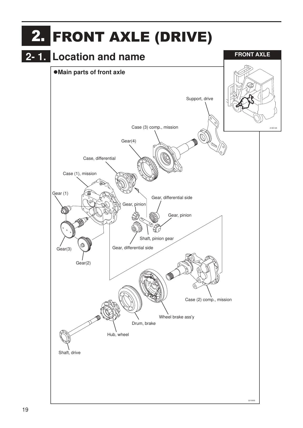
- Front Axle (Drive) — location and name, front axle removal and installation, disassembly and reassembly, gears inspection and replacement, wheel hub and hub bolt inspection, troubleshooting
- Rear Axle (Steering) — location and name, removal and installation, disassembly and reassembly, reassembling method and attention, bushing inspection, center arm inspection, tie rod inspection, knuckle inspection, king pin inspection, hub inspection, rear axle component inspection, troubleshooting
- Tyre — location and name, tyre sizes, hub nut inspection, rim and rim bolt inspection, air pressure inspection, visual inspection and replacement, troubleshooting
- Steering — location and name, steering linkage removal and installation, steering linkage disassembly and reassembly, joint inspection, knob inspection, steering wheel inspection, torque sensor neutral check and adjustment, voltage checking, actuator assembly inspection and adjustment, troubleshooting
- Brake — foot brake linkage, parking brake linkage, wheel brake removal and installation, wheel brake disassembly and reassembly, brake drum inspection, shoe and lining inspection, adjuster assembly inspection, wheel cylinder assembly inspection, master cylinder assembly inspection, brake pedal inspection, parking lever inspection and adjustment, brake linkage adjustment, brake air bleeding, troubleshooting
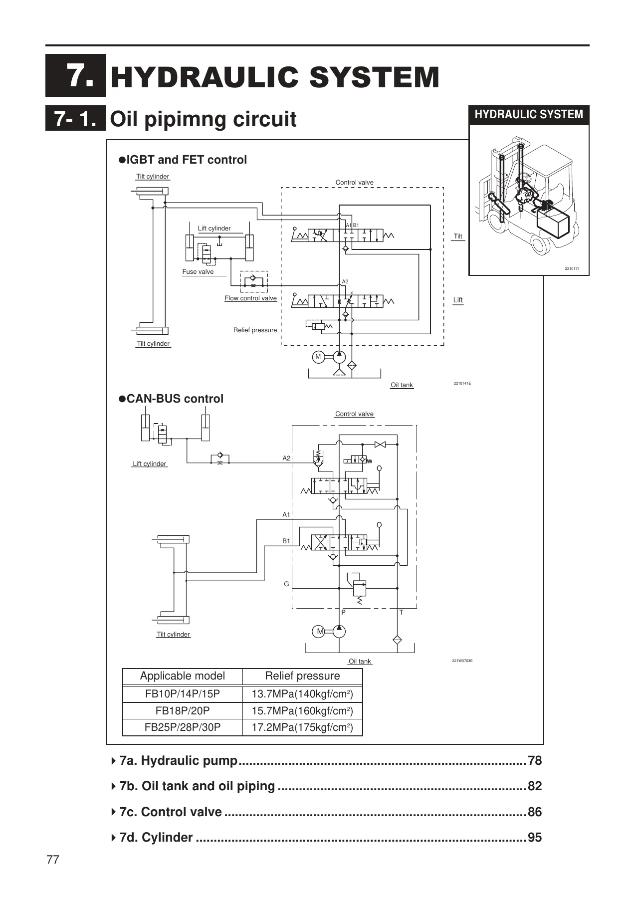
- Hydraulic System — oil piping circuit
- Hydraulic Pump — location and name, removal and installation, inspection, troubleshooting
- Oil Tank and Oil Piping — plastic oil tank, iron oil tank, disassembly precautions, oil piping replacement, oil inspection, recommended oil and quantity, oil tank and filter cleaning and check, troubleshooting
- Control Valve — location and name, removal and installation, inner kit replacement, relief pressure measurement, microswitch adjustment, troubleshooting
- Cylinder — lift cylinder main parts, tilt cylinder main parts, lift cylinder removal for P-mast, PFL-mast and M-mast, tilt cylinder removal, lift cylinder installation and adjustment, tilt cylinder installation, lift cylinder disassembly and reassembly, tilt cylinder disassembly and reassembly, cylinder component inspection, piston rod inspection, drift inspection, tilt angle by masts, troubleshooting
- Mast — location and name, lift bracket removal, mast assembly removal, mast disassembly and reassembly, mast/lift bracket/roller shaft inspection, back shoe inspection, lift chain inspection and replacement, chain bolt inspection, chain wheel inspection, hose pulley inspection, roller inspection and replacement, fork inspection and replacement, lift chain adjustment, mast lean adjustment, troubleshooting
- Motor — traction motor main parts, hydraulic motor main parts, EPS motor main parts, motor specifications, traction motor removal and installation, hydraulic motor removal and installation, EPS motor removal and installation, traction motor disassembly and reassembly, hydraulic motor disassembly and reassembly, EPS motor disassembly and reassembly, rotor inspection, armature inspection, brush and brush holder inspection, motor assembly inspection, oil seal and permanent magnet inspection, troubleshooting
- Electric Parts — location and name
- Control Unit — location, removal and installation, disassembly and reassembly, IGBT module inspection and replacement, FET module inspection and replacement, capacitor inspection and replacement, EPS controller specifications
- Display Panel and Directional Switch — disassembly and reassembly, wiring of directional switch
- Accelerator — removal and installation, potentiometer adjustment, accelerator linkage adjustment
- Main Contactor and Fuse — removal and installation, main contactor inspection and replacement, fuse replacement
- Built-in Charger (Option) — charger assembly disassembly and reassembly, transformer disassembly and reassembly, charger specifications, magnetic contactor inspection, plug and receptacle inspection, fuse and fuse base inspection, transformer inspection, diode inspection, timer inspection, earth inspection, reserve function inspection, automatic charge, reserve charge, balancing charge, voltage tap check and selection, voltage tap changing, fuse replacement
- Battery — removal and installation, battery inspection, battery cleaning
- MPU Board — location and name, MPU board, display board, EPS controller board
- Laser Pointer (Option) — fork level adjustment, laser optical axis adjustment
- Service Data — annual inspection service data, standard work hours
Each system chapter follows the same practical structure: a location-and-name illustration identifying every component, step-by-step removal and installation procedures, detailed disassembly and reassembly with tightening torques marked inline, inspection and adjustment criteria with wear limits and specific values, and a dedicated troubleshooting table listing symptom, possible cause and remedy. This is the structure that makes the FB 75 workshop manual usable at the bench — you can find a component on the exploded view, follow the removal sequence, and cross-check the inspection limits before reassembly, all within the same chapter.
What This Manual Enables You To Do
The Nichiyu FB 75 series is an electric counterbalance forklift with a CAN-BUS control architecture, which means diagnosing electrical faults correctly depends on understanding how the traction motor, hydraulic motor, EPS controller, MPU board and control unit interact. This manual documents that architecture in detail, including the IGBT and FET module inspection procedures, the current sensor and heat sensor circuits, the capacitor discharge procedure, and the EPS controller specifications for both 48V and 72V systems.
On the mechanical side, the manual covers the complete front drive axle with its hypoid differential, the rear steering axle with king pin and knuckle assemblies, the wet-type wheel brake with shoe, lining, adjuster and cylinder components, the full hydraulic system from pump through control valve to lift and tilt cylinders, and the mast with all roller, chain, back shoe and fork inspection values.
For workshops supporting mixed fleets, the manual also documents the built-in charger option, covering automatic charge, reserve charge (with timed start), balancing charge, voltage tap selection for 200V and 400V supplies, and the diagnostic LED sequences for the timer and charging status indicators.
Why the Manufacturer’s Procedures Matter
Torque values on this truck are not guesswork. Front axle fitting bolts are specified at 450–550 N·m, wheel hub nuts vary from 89–108 N·m on the FB10P/14P to 315–385 N·m on the FB20P–30P, and bearing preload is set at 392–686 N·m measured at position A. Hydraulic relief pressures differ by model — 13.7 MPa for the FB10P/14P/15P, 15.7 MPa for the FB18P/20P, and 17.2 MPa for the FB25P/28P/30P. The manual also lists the exact LOCTITE and THREEBOND products to use at specific joints, and the tightening torque table covers 4T and 8T bolts in both SS400 and SCM435 grades.
Get any of these wrong and you risk stripped threads, oil leaks, premature bearing failure, or in the case of the brake and steering systems, a safety-critical fault. Having the correct sequence, the correct shim stacks, the correct seal directions and the correct torque figures in front of you is the difference between a repair that lasts and a comeback.
IMAGES PREVIEW
Instant PDF Delivery
The Nichiyu FB 75 Series CAN-BUS Workshop Manual is delivered as an instant PDF download after payment — no shipping, no waiting for a physical book, no risk of a damaged print. Open it on a laptop, tablet or phone in the workshop, print the pages you need for the job at hand, and keep the rest clean. Every exploded view, wiring layout, hydraulic circuit diagram and specification table is exactly as issued by the manufacturer, so you can work from the same reference the dealer technicians use.
Reviews
There are no reviews yet.