
Nichiyu FB10P-75 to FB30P-75 Electric Forklift Workshop Manual – FB10 FB14 FB15 FB18 FB20 FB25 FB28 FB30P Repair Guide PDF
Original price was: $52.95.$34.95Current price is: $34.95.
Complete 152-page Nichiyu FB10P, FB14P, FB15P, FB18P, FB20P, FB25P, FB28P and FB30P-75 series electric forklift workshop manual. Covers front axle, rear axle, steering, brakes, hydraulic system, mast, motors, control unit, battery and charger. Instant PDF download.
Description
Nichiyu FB10P-75 to FB30P-75 Electric Forklift Workshop Manual
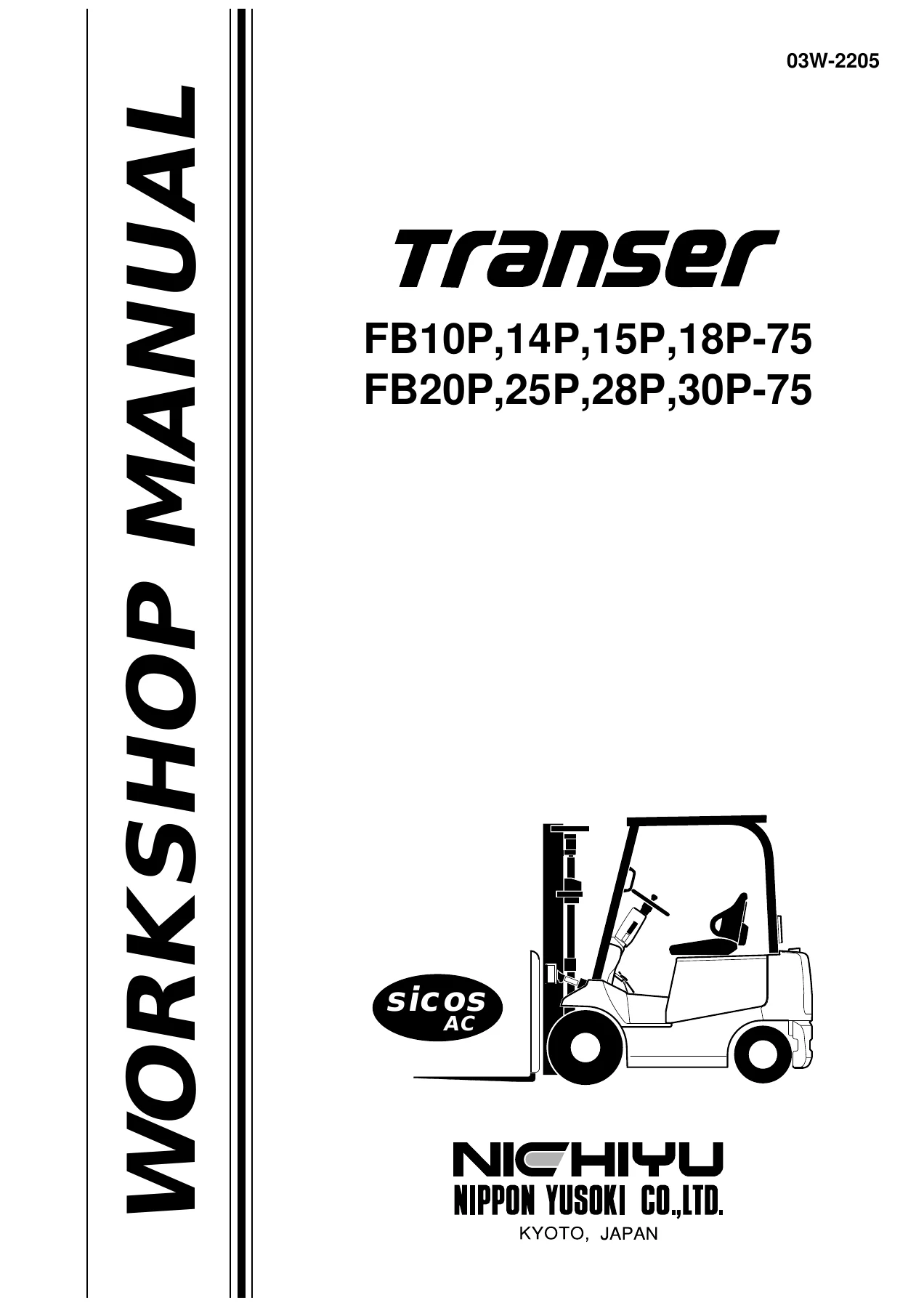
This is the complete Nichiyu FB10P, FB14P, FB15P, FB18P, FB20P, FB25P, FB28P and FB30P-75 series electric forklift workshop manual, document number 03W-2205. Published by Nippon Yusoki Co., Ltd. in December 2003, this 152-page PDF covers the full range of maintenance, disassembly, reassembly, inspection, adjustment and troubleshooting procedures for these pneumatic-tyre electric counterbalance trucks.
File Details
- Manual Type: Workshop Manual
- Brand: Nichiyu (Nippon Yusoki Co., Ltd.)
- Models: FB10P-75, FB14P-75, FB15P-75, FB18P-75, FB20P-75, FB25P-75, FB28P-75, FB30P-75
- Document Number: 03W-2205
- Language: English
- Page Count: 152
- File Format: PDF
- First Printing: December 2003
Chapters Covered
- 1. GENERAL
- 2. FRONT AXLE (DRIVE)
- 3. REAR AXLE (STEERING)
- 4. TYRE
- 5. STEERING
- 6. BRAKE
- 7. HYDRAULIC SYSTEM
- 8. MAST
- 9. MOTOR
- 10. ELECTRIC PARTS
- 11. LASER POINTER
- 12. SERVICE DATA
General Information and Specifications
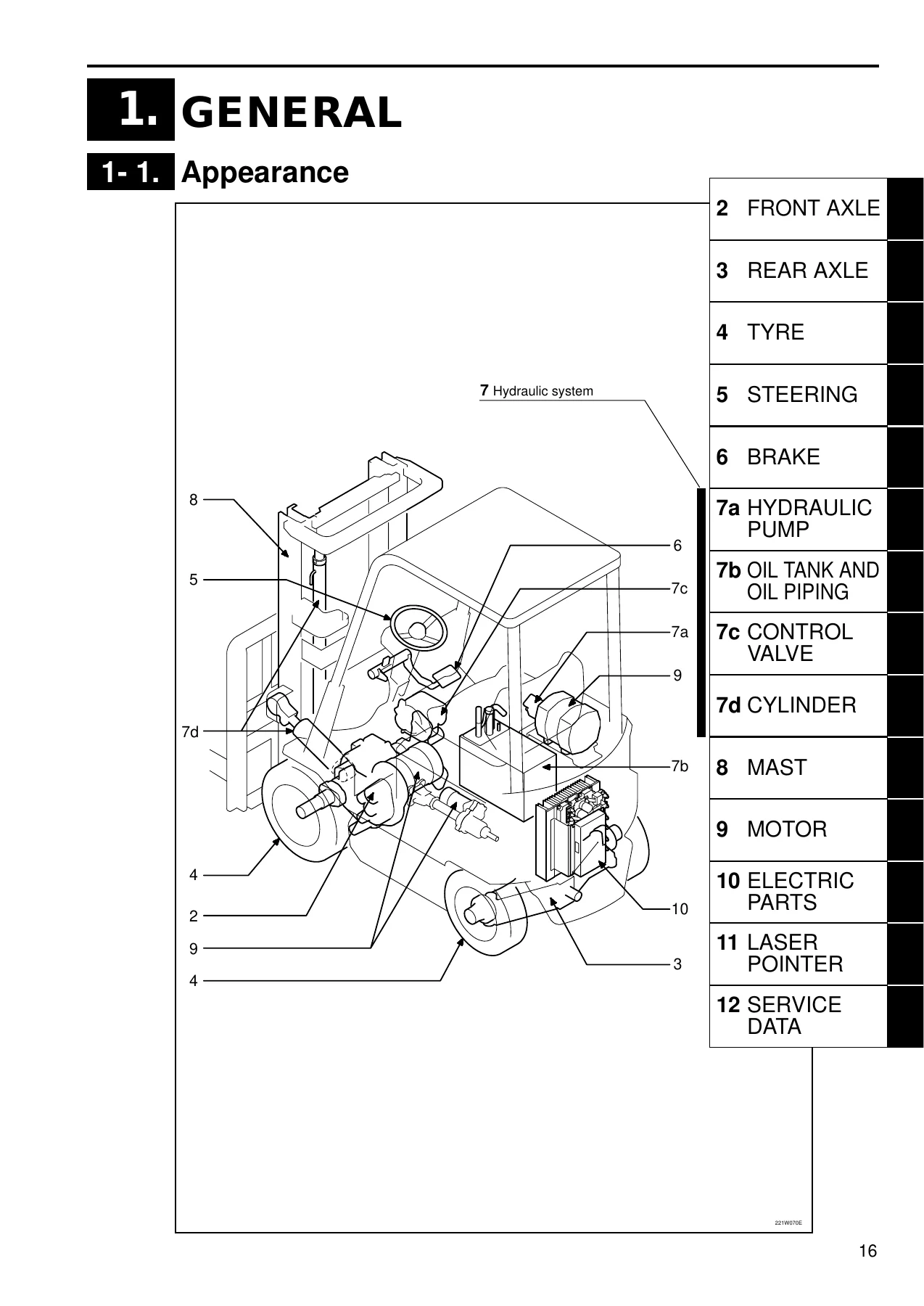
The opening chapter provides the truck’s appearance, component layout and full specifications for the FB-75 series. Model code breakdowns explain capacity ratings from 1000 kg (FB10P) through 3000 kg (FB30P), tyre classification (P for pneumatic), mast types (simplex, duplex PFL, triplex M), and special variants including cold storage (CS, FCS), rust resistant (RP) and dust resistant configurations. This is where you confirm exactly which variant you are working on before any repair.
Front Axle (Drive)
Complete removal and installation of the front axle, including hydraulic hose disconnection, traction motor lead wire removal, parking linkage detachment, tilt pin removal, brake pipe disconnection, and the special pivot cap replacement procedure. Disassembly and reassembly sections cover the transmission case, differential case, gears, drive shafts, wheel hubs and brake drums. Inspection procedures for gears (gearing, wear, scoring, pitting, spline damage), wheel hubs and hub bolts are included, along with a troubleshooting table for continuous noise, abnormal noise when turning, differential heat and oil leakage.
Rear Axle (Steering)
Covers the steering rear axle with location and name references, removal and installation, disassembly and reassembly, and assembly methods and precautions. Inspection and adjustment procedures cover bushings, center arm, tie rod, knuckle, king pin, hub and hub bolts, and the rear axle assembly. A dedicated troubleshooting section addresses rear axle faults.
Tyre, Steering and Brake Systems
The tyre chapter covers location, name and tyre sizes, hub nut inspection, rim and rim bolt inspection, air pressure checks, visual inspection and replacement, plus troubleshooting. The steering chapter covers steering removal and installation, steering linkage disassembly and reassembly, joint and knob inspection and replacement, steering wheel service, torque sensor neutral check and adjustment (including voltage checking), and steering linkage troubleshooting. The brake chapter is extensive: foot brake linkage and parking brake linkage component identification, wheel brake removal and installation, wheel brake disassembly and reassembly with special tools, brake drum inspection and repair limits, shoe and lining inspection and replacement, adjustor assembly service, wheel cylinder and master cylinder inspection and replacement, brake pedal inspection, parking lever adjustment, brake linkage adjustment including pedal height and microswitch position, air discharge procedure, and a comprehensive brake troubleshooting table.
Hydraulic System
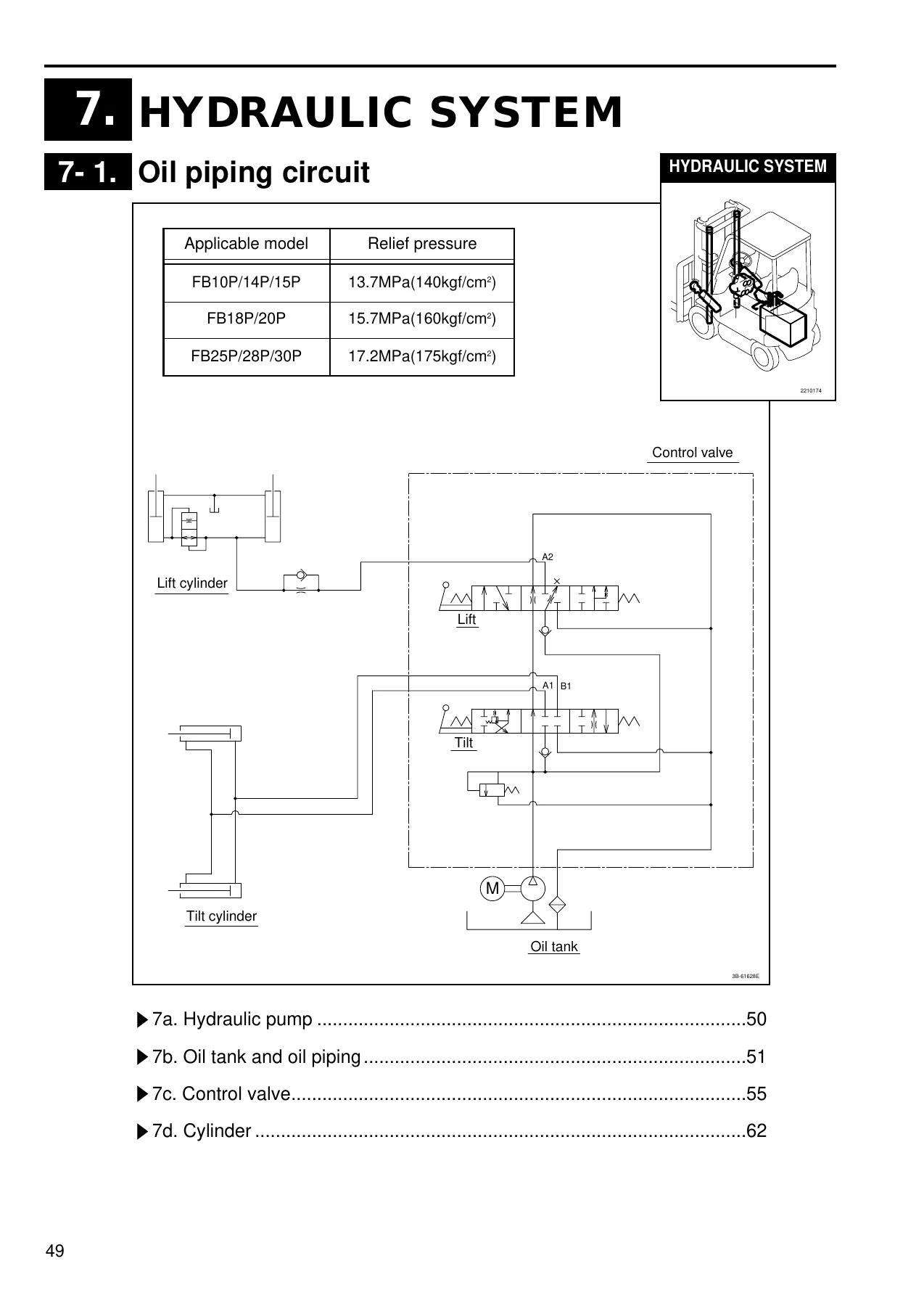
Split into four sub-chapters. The hydraulic pump section covers removal, installation, inspection and troubleshooting. The oil tank and oil piping section covers resin and iron tank configurations, oil inspection criteria, recommended oils and quantities, tank and filter cleaning, and piping replacement precautions. The control valve section covers removal and installation, inner kit replacement, relief pressure measurement with specified values for each model group, microswitch adjustment, and troubleshooting. The cylinder section covers lift cylinder (STD mast, M mast, PFL mast) and tilt cylinder removal, installation, disassembly and reassembly with torque values, inspection and adjustment, drift measurement for lift lowering and tilt, and cylinder troubleshooting.
Mast Assembly
Covers STD simplex, M triplex and PFL duplex mast configurations. Removal of the lift bracket and mast assembly, mast disassembly and reassembly, and inspection and adjustment of mast channels, lift brackets, roller shafts, back shoes, lift chains (with elongation limits and pitch specifications), chain bolts, chain wheels, hose pulleys, rollers, and forks (with wear limits, leveling and opening specifications). Lift chain adjustment and mast inclination adjustment procedures are included, along with a mast troubleshooting table.
Motors
Detailed coverage of the traction motor, hydraulic motor and EPS motor. Includes main part names, specifications for each motor type by model, removal and installation, disassembly and reassembly, and inspection and adjustment. Rotor and armature inspection, brush and brush holder service for the EPS motor, bearing and sensor replacement, motor assembly inspection including abnormal noise checks, insulation testing with Megger, and motor troubleshooting are all covered.
Electric Parts and Control Systems
This major section covers the control unit (location, removal and installation, disassembly and reassembly, capacitor discharging, IGBT module inspection and replacement, capacitor check and replacement, and EPS controller specifications), display panel and directional switch, accelerator, main contactor and fuse (with fuse capacities and tightening torques), charger, battery, and MPU board including the travel/hydraulic board and display board.
Laser Pointer and Service Data
The laser pointer chapter covers fork level adjustment and laser optical axis adjustment. The service data chapter provides annual inspection service data and standard work hours for maintenance, frame, front hood, counterweight, seat, overhead guard, drive assembly, differential gear, wheel hub and brake drum, drive shaft, steering axle, knuckle, tie rod, steering box, steering linkage, wheel brake, foot brake linkage, master cylinder, parking brake, oil tank, hydraulic pump, control valve, lift cylinder, tilt cylinder, piping, valve lever linkage, mast, lift bracket, fork, traction motor, hydraulic motor, EPS motor, control unit, accelerator, indicator panel, main contactor, charger, battery and electric power steering.
Who This Manual Is For
This workshop manual is written for technicians who already have a working knowledge of forklift systems and need the manufacturer’s exact procedures, torque values and diagnostic paths. It is equally useful for fleet maintenance managers who need to understand what a repair involves, and for independent workshops servicing Nichiyu electric forklifts. Every procedure is illustrated with exploded views, component layouts and circuit diagrams, and every specification is given in the units used by the manufacturer.
Get Instant Access
IMAGES PREVIEW
This Nichiyu FB10P-75 to FB30P-75 electric forklift workshop manual is delivered as an instant PDF download. There is no shipping, no waiting and no physical book to lose. Open it on a laptop in the workshop, a tablet next to the machine, or print the pages you need for the job at hand. Whether you are rebuilding a front axle, adjusting brake pedal height, measuring relief pressure, replacing a lift chain or diagnosing a control unit fault, the correct procedure and the right specification are always within reach.
Reviews
There are no reviews yet.