Nichiyu FB50 Series FB10/14/15/18P.PL-50 FB20/25/28/30P.PL-50 EPS Troubleshooting Manual PDF
$13.95
Nichiyu Forklift FB50 Series FB10/14/15/18P.PL-50 FB20/25/28/30P.PL-50 EPS Troubleshooting Manual – PDF DOWNLOAD
Description
Nichiyu Forklift FB50 Series FB10/14/15/18P.PL-50 FB20/25/28/30P.PL-50 EPS Troubleshooting Manual – PDF DOWNLOAD
FILE DETAILS:
Nichiyu Forklift FB50 Series FB10/14/15/18P.PL-50 FB20/25/28/30P.PL-50 EPS Troubleshooting Manual – PDF DOWNLOAD
Language : English
Pages : 29
Downloadable : Yes
File Type : PDF
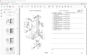
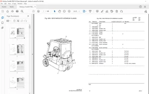
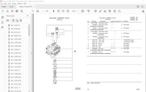
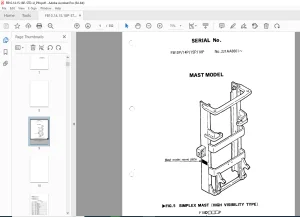
IMAGES PREVIEW OF THE MANUAL:
TABLE OF CONTENTS:
Nichiyu Forklift FB50 Series FB10/14/15/18P.PL-50 FB20/25/28/30P.PL-50 EPS Troubleshooting Manual – PDF DOWNLOAD
EPS Trouble-shooting manual 1
Contents 2
1 Electric power steering for FB series 3
1 1 What is EPS? 3
1 2 Features 3
1 3 Action of EPS 3
1 4 Fail safe function of controller 4
1 5 Truck equipped with EPS 4
2 EPS Trouble-shooting 5
2 1 Precautions on trouble-shooting 5
2 2 Trouble-shooting procedures 6
EPS contactor (M7) does not go on 7
EPS contactor (M7) immediately trips 8
EPS contactor (M7) trips as soon as wheels are steered 9
EPS contactor (M7) goes on but steering is impossible 10
Steering is possible but abnormally hard 11
Steering is possible but catches roughly 12
Steering vibrates 13
Steers by itself 14
EPS motor is over-heated 15
3 Replacement and adjustement of parts 16
3 1 Interchangeability of majors parts 16
3 2 Wearing limit of EPS motor brushes 16
3 3 Adjustement on replacement of torque sensor 16
3 4 Adjustment on replacements of actuator ass’y 18
4 wiring and components 19
location of components 19
Pictorial wiring 20
Wiring diagram (EPS only) 21
Wiring diagram (chassis) 22
5 Disassembling actuator ass’y 23
5 1 Disassembling procedure and construtive parts of actuator ass’y 23
1 Fixing actuator horizontally to a vice 23
2 Removing motor ass’y 24
3 Removing universal joint comp 24
4 Removing cover 24
5 Removing idle gear 25
6 After disassembling 25
5 2 Inspection 26
5 3 Assembling 26
S.V 06/24