
Nichiyu FBT-13P 15P 18P 20PN-75 Electric Forklift Troubleshooting Manual – SICOS-AC PDF
Original price was: $29.95.$17.95Current price is: $17.95.
Nichiyu FBT-75 series electric forklift troubleshooting manual covering SICOS-AC adjustment, self-diagnosis error codes, error history memory, I/O checks and full body wiring diagrams for FBT-13P, FBT-15P, FBT-18P and FBT-20PN-75 trucks.
Description
Nichiyu FBT-75 Series Electric Forklift Troubleshooting Manual
This is the complete Nichiyu FBT-13P 15P 18P 20PN-75 Electric Forklift Troubleshooting Manual issued for the SICOS-AC control system fitted to the FBT-75 series battery-powered counterbalance trucks. It is a working document written for technicians who already understand electric lift truck systems, and it takes the reader from basic monitor display interpretation all the way through to board-level diagnosis, parameter adjustment and connector pinout identification. Every procedure, error code, parameter range and wiring diagram needed to fault-find the traction, hydraulic and power steering circuits of these trucks is contained in one file.
File Details
- Manual type: Troubleshooting / adjustment manual
- Brand: NICHIYU (Nichiyu Electric Lift Trucks)
- Series covered: FBT-13P to FBT-20PN-75
- Control system: SICOS-AC
- Document number: E-07W-2204
- Language: English
- Page count: 104 pages
- File format: PDF
Chapters Covered
- 1. Adjustment of SICOS-AC
- 1-1. Explanation of the monitor display
- 1-1-1. Indicator panel
- 1-1-2. Indication of display
- 1-1-3. Function of display
- 1-1-4. Various kinds of mode selection
- 1-2. Explanation of control boards
- 1-2-1. Basic control board construction
- 1-2-2. Travel/Hydraulic board
- 1-2-3. EPS controller board
- 1-2-4. Rotary switch on the Travel/Hydraulic board
- 1-2-5. Rotary switch on the EPS controller board
- 1-2-6. Adjustment Standards List for FBT-75 series
- 1-2-7. Other settings
- 1-3. SICOS-AC check and adjustment
- 2. Troubleshooting
- 2-1. Self diagnosis function
- 2-1-1. Display
- 2-1-2. Error messages and conditions to appear
- 2-2. Error history memory
- 2-2-1. Error history memory 1
- 2-2-2. Error history memory 2
- 2-2-3. Clearing the error history memory
- 2-3. I/O Check
- 2-3-1. Indication of the I/O check mode
- 2-3-2. I/O port table
- 3. Wiring (Diagrams)
- 3-1. Wiring, system (Body / Fingertip)
- 3-2. Wiring, body
- 3-3. Harness, body and lead wire chart
- 3-4. Controller wiring
- 3-5. Controller harness
- 3-6. Main controller ASSY
- 3-7. Wiring, BC (3-phase 200V / 3-phase 400V)
- 3-8. Harness, BC
- 3-9. Wiring, lamp
- 3-10. Forward & backward chime / buzzer
- 3-11. Wiring, lift limit
- 4. Reference
- 4-1. MPU board connectors
- 4-1-1. Pin arrangement of connector housing
- 4-1-2. Name of parts
- 4-1-3. Installation of terminals into housing
- 4-1-4. How to extract terminals
- 4-1-5. Crimp tools
- 4-2. Water resistant connector
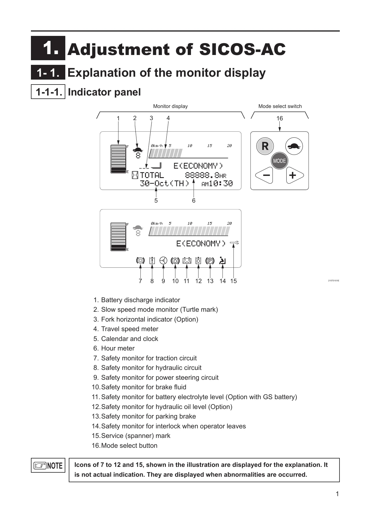
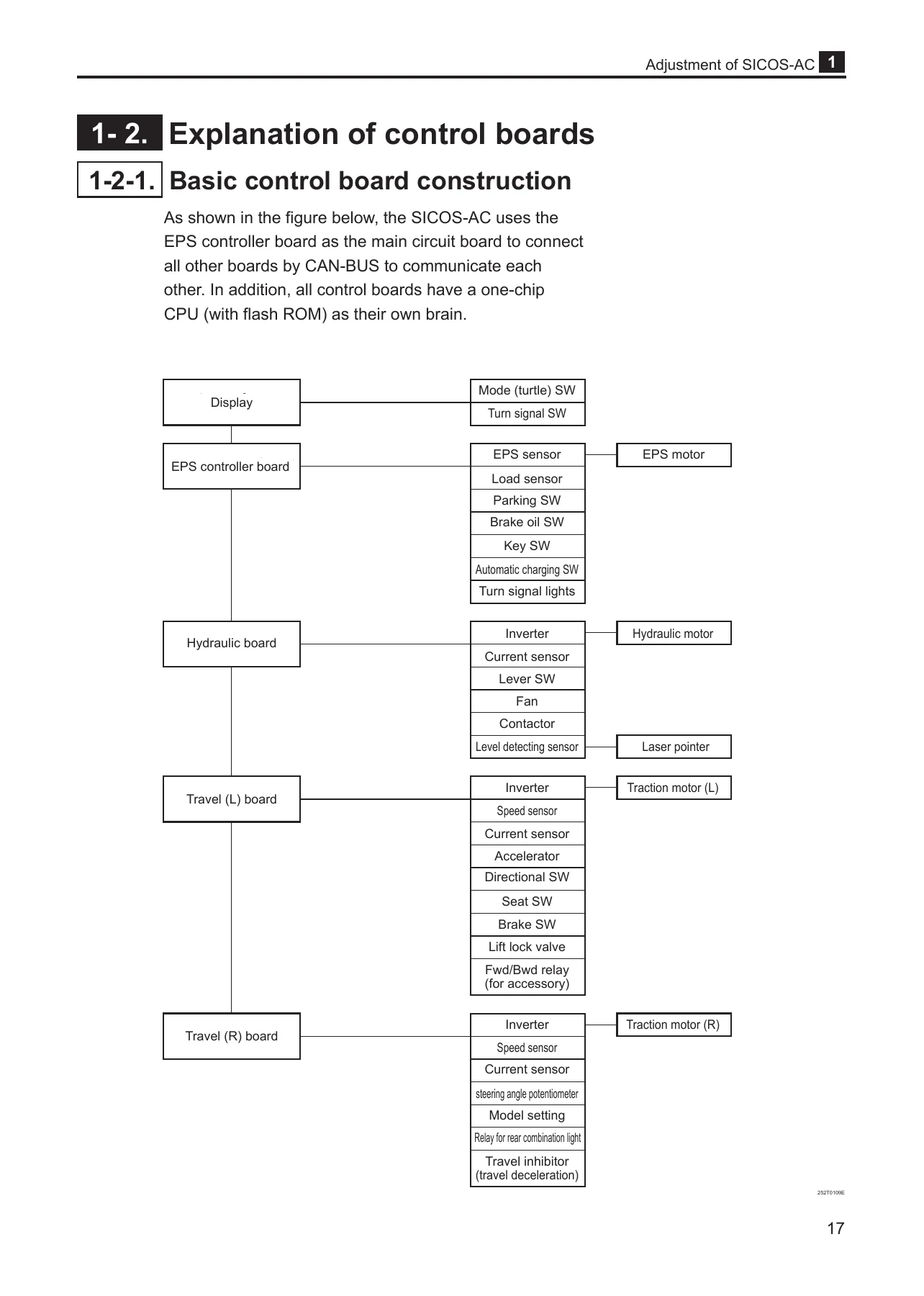
Taken as a whole, the document is a single-machine fault-finding reference rather than a general theory book. The opening chapter teaches the technician to read the truck’s own instruments first: the battery discharge indicator, travel speed meter, hour meter, calendar and clock, and the bank of safety monitors for the traction circuit, hydraulic circuit, power steering circuit, brake fluid, battery electrolyte level, hydraulic oil level, parking brake, operator interlock and service warnings. From there it moves into the boards themselves, explaining how the EPS controller board acts as the main board linking the Travel, Travel/Hydraulic and display boards over CAN-BUS, what the P7, P15 and CPU LEDs should be doing when the key switch is on, and how the rotary switches RS1 on each board select models, options and adjustment screens.
The bulk of the first chapter is a step-by-step adjustment sequence covering chassis insulation testing, battery voltage calibration, current sensor checks on the traction and hydraulic circuits, model setting, hydraulic function setting, switch back (plugging/regenerative) braking force, regenerative braking force, display monitor symbols, display language, optional functions, display brightness, hour meter operation, auto power off, battery electrolyte level, turn signal lamp, load sensor calibration, cooling fan, lift interrupt, accelerator potentiometer, steering angle potentiometer, OIS operation and the built-in charger.
Self-Diagnosis, Error Codes and Error History
The troubleshooting chapter explains what the truck itself reports and how to read it. Error messages are grouped by system, so a traction fault such as B10:FUSE-TRAVEL, B11:FET-TRAVEL, B12:SENSOR-CURRENT TRAVEL, B13:DIRECTIONAL SW or B14:ACCELERATOR flashes the traction icon and scrolls the message, while hydraulic and steering faults appear under their own codes such as C21:FET-HYD, C22:SENSOR-CURRENT HYD, C23:SWITCH-LIFT, D30:FUSE-EPS, D31:SENSOR-EPS TORQUE and D32:TR-EPS MAIN. The manual lists each message alongside its likely cause and any accompanying advisory text such as *FAIL OPERATION*, *TURN OFF KEY SWITCH*, *FAIL CURRENT-TRAVEL* or *REDUCE DUTY-OPERATION*.
Two error history memories are documented. Error history memory 1 holds the ten most recent errors in order of occurrence, and the manual shows how to step through each entry to read the date, time, hour meter reading at the moment the fault occurred, and the number of times that fault has been recorded. Error history memory 2 lists every detectable error code with the ones that have actually occurred highlighted, giving a service history of the truck at a glance. The procedure for clearing the memories by setting RS1 to “E” is also included, along with the list of parameters returned to default when the memory is initialised.
The I/O check section is what turns the manual into a genuine diagnostic tool. With RS1 set to “8” the technician can select the Travel (Left), Travel (Right), Hydraulic or EPS processor, enter an address such as W0014 or W0006, and read the live hexadecimal and binary state of that port. The I/O port tables map each bit to its function, covering forward and backward outputs, directional switches, seat switch, travel inhibit, turning speed reduction, accelerator and turning potentiometers, main contactor, fan drive, lift and tilt switches, attachment switches, key switch positions, brake and hydraulic oil level inputs, overload sensor, parking brake, battery electrolyte level, charger switches and the charger contactor and LED outputs.
Wiring Diagrams and Connector Reference
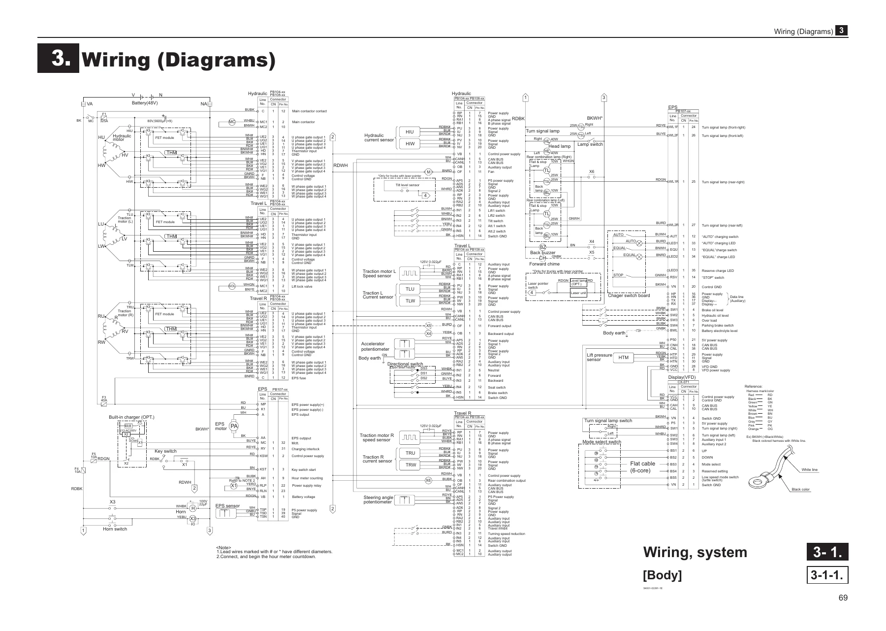
The wiring chapter reproduces the full system wiring diagram for the body and fingertip configurations, body wiring, harness layout and lead wire chart, controller wiring and harness, main controller assembly, built-in charger wiring for both 3-phase 200V and 3-phase 400V supplies, lamp wiring, forward and backward chime and buzzer wiring, and the lift limit circuit. Individual harness drawings show connector numbering, wire colours, line numbers, lead lengths and braided wire runs, which makes tracing a broken or chafed circuit far quicker than working from the machine alone.
The reference chapter closes the manual with MPU board connector information: pin arrangement of each connector housing, the name of each housing and terminal part, the correct method for installing terminals into a housing and confirming the double lock plate has seated, how to extract terminals using the specified extractor, and the AMP crimp tool part numbers. Water resistant connector pin arrangements for 2-pin, 6-pin and 8-pin receptacles and tabs are also given, together with the seal plug, rubber plug and pressure terminal part numbers.
What This Manual Lets You Do
With this Nichiyu FBT-13P 15P 18P 20PN-75 troubleshooting manual on hand, a technician can diagnose a dead or derated truck from the display outward instead of guessing at components. The error code tables point straight at the circuit or sensor responsible, the adjustment standards list gives the correct parameter for each FBT-75 model, and the wiring diagrams let the fault be confirmed at the connector before any board or motor is condemned. Battery voltage calibration, current sensor verification, accelerator and steering angle potentiometer setting, load sensor calibration and regeneration and plugging brake force adjustment are all covered with the actual values to work to, which matters because an incorrectly calibrated potentiometer or a mis-set model rotary switch can produce fault codes that have nothing to do with the real problem.
Shop owners and fleet maintenance teams get a repeatable procedure for every SICOS-AC adjustment, so trucks coming out of service come back with the same braking feel, lift speed and travel response as the rest of the fleet. The I/O check tables in particular are difficult to reconstruct from memory and save hours when a fault is intermittent.
IMAGES PREVIEW
Delivery is instant. The manual is supplied as a PDF that downloads immediately after payment, with no shipping and no waiting for a disc or a printed binder. It can be opened on a laptop, tablet or phone in the workshop, searched page by page on screen, and printed in full or one section at a time so the relevant wiring diagram or adjustment screen can sit next to the truck while you work.
Reviews
There are no reviews yet.