Nichiyu Forcea Forklift FBC20P,25P,30P-70 Workshop Manual PDF
$26.95
Nichiyu Forcea Forklift FBC20P,25P,30P-70 Workshop Manual – PDF DOWNLOAD
Description
Nichiyu Forcea Forklift FBC20P,25P,30P-70 Workshop Manual – PDF DOWNLOAD
FILE DETAILS:
Nichiyu Forcea Forklift FBC20P,25P,30P-70 Workshop Manual – PDF DOWNLOAD
Language : English
Pages : 107
Downloadable : Yes
File Type : PDF
IMAGES PREVIEW OF THE MANUAL:
TABLE OF CONTENTS:
Nichiyu Forcea Forklift FBC20P,25P,30P-70 Workshop Manual – PDF DOWNLOAD
SAFETY WORK 1
1 Precautions for safe inspection and
maintenance work 1
2 Safety labels • • 5
3 Model name and serial numbers 9
4 Cautions for maintenance 11
5 Tightening torque for bolts 14
6 Maintenance tools and inspection devices 15
1 GENERAL 16
1-1 Арреагапсе 16
1-2 Specifications 17
2 FRONT AXLE (DRIVE)
2-1 Location and name
2-2 DisassemЬly and reassemЫy
2-2-1 Front axle – removal and installation
2-2-2 Front axle – disassemЫy and reassemЫy
2-3 lnspection and adjustment
2-3-1 Gears – lnspection and replacement
2-3-2 Wheel hub and hub bolt – lnspection
2-4 TrouЬleshooting
2-4-1 Front axle – trouЫeshooting
3 REAR AXLE (STEERING) 19
3-1 Structure and cautions for
disassemЫy, reassemЬly 19
3-1-1 Rear axle – disassemЫy and reassemЫy 19
3-1-2 Rear axle assemЫy – methods and
precautioпs 22
3-1-3 Discharging air from
the auto suspensian cylinder 23
3-2 lnspection and adjustment 25
3-2-1 Bushing – inspection 25
3-2-2 Knuckle – inspection
3-2-3 King pin – inspection
3-2-4 Hub and hub bolt – inspection
3-2-5 Rear axle comp – inspection
25
25
26
26
3-4 TrouЫeshooting 27
3-4-1 Rear axle – trouЫeshooting 27
4 ТУRЕ
4-1 Location, паmе апd tyre size
4-1-1 Tyre name
4-1-2 Tyre size
4-2 lnspection апd adjustment
4-2-1 Hub nut – inspection
4-2-2 Rim and rim bolt – inspection
4-2-3 Air pressure – inspection
4-2-4 Туге – visual inspection and replacement
4-3 TrouЫeshooting
4-3-1 Tyre – trouЫeshooting
5 STEERING 28
5-1 Structure апd cautions for
disassemЫy, reassemЫy • 28
5-1-1 Steering linkage – disassemЫy
and reassemЫy 28
5-2 lnspection апd adjustment 29
5-2-1 Joint – inspection and replacement 29
5-2-2 КпоЬ – inspection and replacement 29
5-2-3 Steering wheel – inspection
and replacement 29
5-3 TrouЬleshooting • 30
5-3-1 Steering linkage – trouЫeshooting 30
6 BRAKE 31
6-1 Structure and cautions for
disassemЫy, reassemЫy 31
6-1-1 Foot brake llnkage
– disassemЫy and reassemЫy
6-1-2 Parking brake linkage
– dlsassemЫy and reassemЫy
6-2 DisassemЫy апd reassemЫy
6-2-1 Wheel brake – removat апd installation
6-2-2 Wheel brake – disassemЫy and reassemЫy
31
32
J
1
j
J
J
J
J
J
J
J
г
г
г
1
( __ _
г 1
г
г
г
г
г
г
г
г
See the “FB-75 WORKSHOP MANUAL” (ОЗW-2205) for the chapters whose pages are not
mentioned in the “Contents”
6-3 lnspection and adjustment
6-3-1 Brake drum -inspection, repair and replacement
6-3-2 Shoe & lining – inspection and replacement
6-3-3 Adjustor ass1y- inspection and replacement
6-3-4 Wheel cylinder ass’y – inspection and replacement
6-3-5 Master cylinder ass’y – inspectlon and
replacement 33
6-3-6 Brake pedal – inspection 33
6-3-7 Parking lever – inspection and adjustment 34
6-3-8 Brake linkage – adjustment 34
6-3-9 Discharge air from the brakes 36
6-4 TrouЫeshooting 38
6·4-1 Brake – trouЬleshooting 38
7 HYDRAULIC SYSTEM 40
7-1 Oil piping circuit 40
7-1-1 Oil piping circuit- power steering 40
7а HYDRAULIC PUMP 41
7а-1 Structure and cautions for
disassemЫy, reassemЫy 41
7а-1-1 Hydraulic pump – removal and installation 41
7а-1-1 Hydraulic pump type 42
7а-2 lnspection and adjustment 42
7а-2-1 Hydraulic pump – inspection 42
7а-3 TrouЫeshooting 43
7а·4-1 Hydraulic pump – trouЫeshooting 43
7Ь OIL TANK AND OIL PIPING 44
7Ь-1 Structure and cautions for
disassemЫy, reassemЫy 44
7Ь-1-1 Oil tank – precautions 44
7Ь-1-2 Oil piping replacement – precautions 45
7Ь-2 lnspection and adjustment 46
7Ь-2-1 Oil – inspection 46
7Ь-2-2 Recommended oil and oil quantity 46
7Ь-3-3 Oil tank and filters – cleaning and check 47
_7Ь-3 TrouЫeshooting 47
7Ь·3-1 Oil tank – trouЫeshooting 47
7с CONTROL VALVE 48
7с-1 Structure апd cautions for
disassemЫy, reassemЫy 48
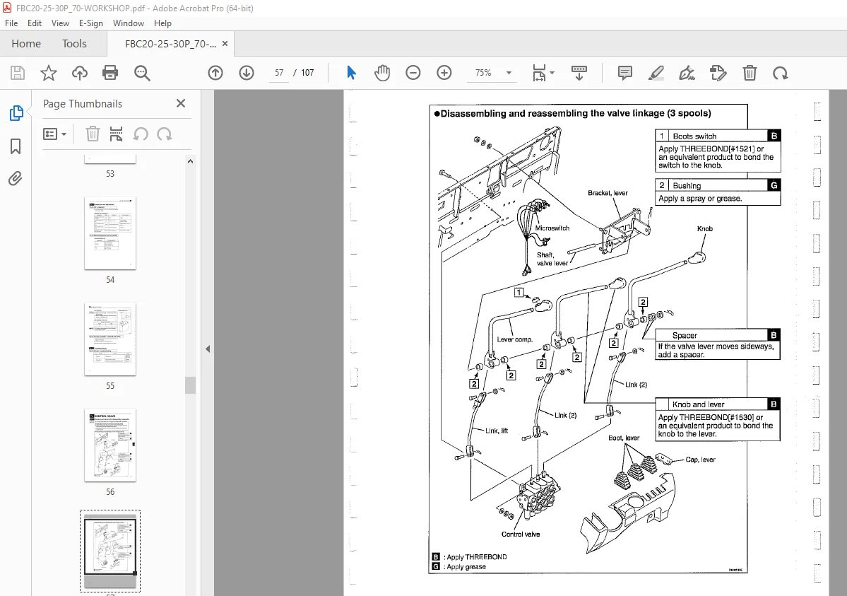
7с-1-1 Control valve
– disassemЫy and reassemЫy 50
7с-2 lnspection апd adjustment 52
7с-2-1 Relief pressure – measurement 52
7с-2-2 Microswitch – adjustment 52
7с-3 TrouЬleshooting 53
7с-3-1 Control valve – trouЫeshooting 53
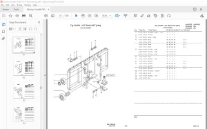
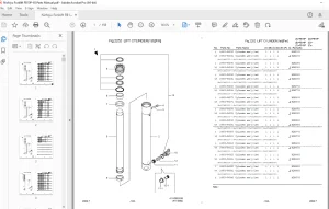
7d CYLINDER
7d-1 Location and паmе
7d-1-1 Lift cylinder – main part names
7d-1-2 Тilt cylinder – main part names
7d-2 DisassemЫy and reassemЫy
7d-2-1 Lift cylinder (STD mast) • removal
7d-2-2 Llft cylinder 2nd (M/PFL mast) – removal
7d-2-3 Тilt cylinder – removal
7d-2-4 Lift cylinder (STD mast) – installation
7d-2-5 Lift cyllnder 2nd (M/PFL mast) – installation
7d-2-6 Тilt cylinder • installation
7d-2-7 Lift cylinder-disassemЫy and reassemЫy
7d-2-8 Тilt cylinder- disassemЫy and reassemЫy
7d-3 lnspection and adjustment
7d•3-1 Cylinder comp – inspection
7d-3-2 Piston rod – inspection
7d·3·3 Drift of lift lowerlng and tllt – inspection
7d-4 TrouЫeshooting
7d•4-1 Cylinder – trouЬleshooting
7е POWER STEERING PUMP AND
POWER STEERING PIPING 54
7е-1 Structure and cautions for
disassemЫy, reassemЫy 54
7е-1-1 Power steering pump
– disassemЫy and reassemЫy
7е-1-2 Power steering piping
– disassemЫy and reassemЫy
54
55
7е-1-3 Power steering piping replacement – precautions 56
7е-2 lnspection and adjustment 57
7е-2-1 Power steering pump – inspection 57
See the “FB-75 WORKSHOP MANUAL” (ОЗW-2205) for the chapters whose pages are not
mentioned in the “Contents”
7е-3 TrouЫeshooting
7е-3-1 Power steering pump – trouЫeshooting
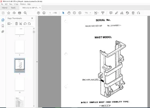
8 MAST
8-1 Location and name
8-2 DisassemЫy and reassemЫy
8-2-1 Lift bracket ass’y – removal
8-2-2 Mast ass’y – removal
8-2-3 Mast – disassemЫy and reassemЫy
8-3 lnspection and adjustment
8-3-1 Mast, lift bracket and roller shaft – inspection
8-3-2 Back shoe – inspection
8-3-3 Lift chain – inspection and replacement
8-3-4 Chain bolt – inspection
8-3-5 Chain wheel – inspection
8-3-6 Hose pulley – inspection
8-3-7 Roller- inspectlon
8-3-8 Fork – inspection
8-3-9 Lift chain – inspectlon and adjustment
8-3-1 О Mast inclination – inspection and adjustment
8-4 TrouЫeshooting
8-4-1 Mast – trouЫeshooting
9 MOTOR 58
9-1 Structure and cautions for
disassemЫy, reassemЫy 58
9-1-1 Traction motor- disassemЫy and reassemЫy 58
9-1-2 Hydraulic motor – disassemЫy and reassemЫy 59
9-1-3 PS motor – disassemЫy and reassemЫy 59
9-1-4 Motors – specifications 60
9-2 lnspection and adjustment 61
9-2-1 Rotor comp – inspection and replacement
(Тraction and hydraulic motor) 61
9-2-2 Armature comp – inspection and replacement 62
9-2-3 Brush, brush holder and spring
(PS motor) – inspection and replacement 62
9-2-4 Motor ass’y – inspection
(Тraction motor and Hydraulic motor) 64
9-2-5 Motor ass’y (PS motor) – inspection 65
9-3 TrouЫeshooting 66
9-3-1 Motor – trouЫeshooting 66
1 О ELECTRIC PARTS 67
10-1 Location and name • 67
10а CONTROL UNIT 68
1 Оа-1 Location and name 68
1 Оа-2 DisassemЫy and reassemЫy 69
1 Оа-2-1 Control unit – removal and installation 69
1 Оа-2-2 Control unit – disassemЫy and reassemЫy 71
1 Оа-3 Check and replacement 73
1 Оа-3-1 Module, IGBT – inspection and replacement 73
1 Оа-3-2 Capacitor – check and replacement 75
1 Оа-3-3 Capacitor – discharging procedure 75
10Ь DISPLAY PANEL AND
DIRECTIONALSWITCH 76
1 ОЬ-1 DisassemЫy and reassemЫy 76
1 ОЬ-1 -1 Display panel – disassemЫy
and reassemЫy 76
1 ОЬ-1-2 Directional switch – disassemЫy
and reassemЫy 77
S.V 06/24