Nichiyu Forklift 60 Series FBT 13P/15P/18P Workshop Manual PDF
$26.95
Nichiyu Forklift 60 Series FBT 13P/15P/18P Workshop Manual – PDF DOWNLOAD
Description
Nichiyu Forklift 60 Series FBT 13P/15P/18P Workshop Manual – PDF DOWNLOAD
FILE DETAILS:
Nichiyu Forklift 60 Series FBT 13P/15P/18P Workshop Manual – PDF DOWNLOAD
Language : English
Pages : 157
Downloadable : Yes
File Type : PDF
IMAGES PREVIEW OF THE MANUAL:
TABLE OF CONTENTS:
Nichiyu Forklift 60 Series FBT 13P/15P/18P Workshop Manual – PDF DOWNLOAD
Work shop manual 1
Contents 2
Introduction 3
Model coding system and name plate 4
1 Model coding system 4
Plate, name (Mode & rating) 5
Location of serial and lot numbers 8
Stability of forklift truck 10
Before starting to work 11
Thightening torque of bolts 12
Front axle 13
1 Structure of front axle 14
2 Service data and specification 15
Specifications 15
3 Troubleshooting 15
Front wheel and hub 16
Reduction gear 16
4 Removing procedure 17
5 Disassembling 18
6 Inspection 19
7 Assembling 19
8 Adjustment of hub ass’y 19
9 Installation 20
Rear axle 22
Structure of rear axle 23
1 FBT10P/ 13P 23
2 FBT15P/18P 24
Disassembling and assembling of rear axle 25
1 FBT10P/13P 25
2 FBT15P/18P 27
3 Power steering cylinder 28
Inspection 29
Tyre 30
1 Removal of tyre 31
2 Tyre size 31
3 Inspection 31
4 Procedure to replace tyres 33
5 Installation of tyre 34
Steering linkage 35
1 Disassembling and assembling 36
2 Column ass’y 37
Brake linkage 40
1 Brake piping 41
2 Removal of disk brake ass’y 42
3 Procedure to disassemble the disk brake ass’y 42
4 Inspection of brake pad 43
5 Replacement of pad 43
6 Disassembling of wheel cylinder ass’y 43
7 Assembling 44
8 Installation 45
9 Master cylinder ass’y and brake pedal 46
Removal 46
Procedure to disassemble 46
Inspection 46
Procedure for assembling 48
Parking brake 49
1 Removal 50
2 Installation and adjustment 50
Hydraulic system 52
Oil piping 53
1 Hydraulic circuit 53
2 Frame piping (Tank-Pump-Valve) 54
3 Frame piping (Valve-Tilt cyclinder) 55
Oil tank 56
1 Dissambling and assembling 56
2 Inspection 57
3 Oil and quantity 57
Pump 59
1 Removal and installation 59
Valve linkage 61
1 Disassembling and assembling 61
Control valve 62
1 Replacement of inner kit or relief valve 62
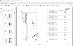
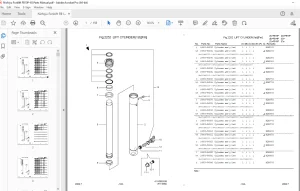
Cylinder 66
1 Cylinder ass’y (Lift cyclinder) 67
Removal 67
Caution for disassembling 69
Inspection of lift cylinder 70
Points for assembling 70
Points for assembling 71
Check and adjustment 71
2 Cylinder ass’y (Tilt cylinder) 73
Removal 73
Rod head 74
Inspection of lift cylinder 75
Points for assembling 76
Check and adjustment after installation 77
3 Oil piping 78
Caution for replacing hoses 78
Mast 79
1 Cylinder ass’y (Lift cylinder) 80
2 Disassembling procedure and caution 82
3 Inspection 84
4 Assembling and point 87
5 installation and points 88
Motor 90
1 Removal and installation 91
Removal and installation 91
Hydrualic motor 91
Power steering motor 92
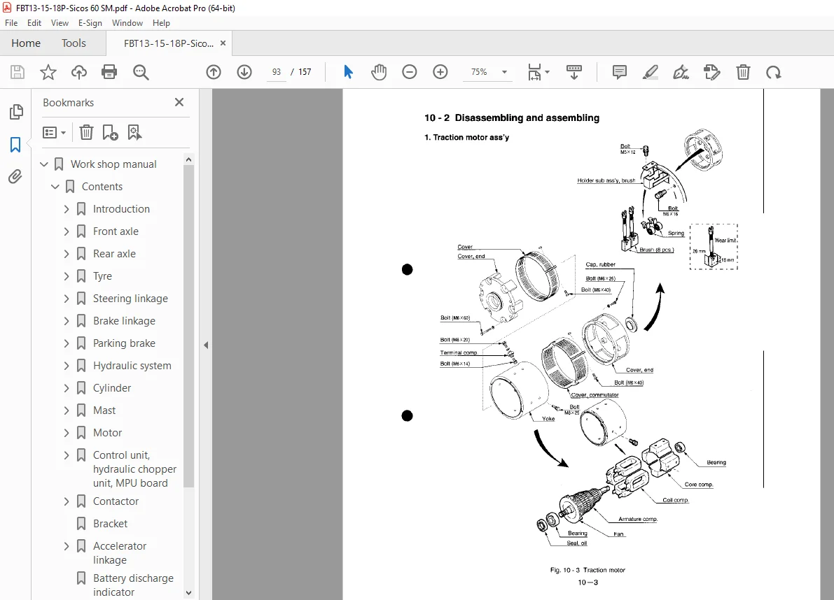
2 Disassembling and assembling 93
Traction motor ass’y 93
Hydraulic motor 94
Power steering motor 96
3 Inspection 96
armature comp 96
Carbon brush, brush holder, spring 98
Field coil 99
Diode (for the truck without hydraulic chopper) 100
4 Assembling and hint 100
Assembling of the field coil isolation test 100
Assembling the brush holder 101
Tightening torque 102
Inspection of motor ass’y 102
5 Trouble shooting 103
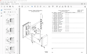
Control unit, hydraulic chopper unit, MPU board 104
1 Parts and layout 105
Control unit (CU51-89) 105
Control unit (CU51-87) 106
Hydraulic chopper unit (CB42-33) 107
MPU board (PBC84-30) 108
2 Applicable parts 109
3 Removal of control unit 109
4 Caution and procedure to remove parts 111
Removal of the diode (D) and the heat sink 111
Removal of FET comp 111
Removal of current sensor comp 112
Removal of condenser 112
Removal of pre-excitation board (for regeneration) 113
5 Inspection 114
Diode 114
FET comp 114
Condenser 115
6 Caution and procedure to assembling each part 116
Installation of diode and heat sink 116
Installation of FET comp 117
Installation of current sensor (la) and (if) 118
Installation of condenser 119
Installation of pre-excitation board (regeneration) 119
7 Installation of control unit 120
Contactor 121
1 Layout of each contactor and removal 122
Forward/reverse contactor 122
By-Pass contactor 123
Hydraulic contactor 124
power steering contactor 126
2 Disassembling procedure of contactor comp 128
Disassembling procedure of hydraulic contactor 128
3 Inspection 129
4 assembling procedure and point 130
Bracket 132
Accelerator linkage 133
1 Parts 133
2 Structure of accelerator sensor and features 133
2 Adjustment 134
Battery discharge indicator 135
Indicator panel 136
1 Parts name and display 136
2 Disassembling procedure 137
2 Assembling and points 137
Directional switch 138
1 Removal 139
2 Disassembling procedure 139
Fuse 140
1 Replacing of fuse 141
2 Claw-type fuse 142
Battery and battery plug 143
1 Inspection of battery 144
Electrolyte level 144
check the specific gravity of each cell 145
2 Cleaning 146
Cell, connecting bar and terminal 146
Vent plug 146
3 inspection of battery plug 147
Repair of contact 147
4 Troubleshooting 148
Charger 149
1 Removal 150
Removal of charger unit ass’y 150
Removal of transformer 150
2 inspection 151
Magnetic contactor 151
Plug consent 152
Fuse and fuse holder 152
Transformer 152
Diode 153
3 Assembling and points 153
4 Inspection after assembling 154
Inspection of timer 154
5 Adjusting of input voltage 156
Check input voltage 156
Selection of the voltage tap 156
Changing of tap 156
6 Troubleshooting 157
S.V 06/24