
Nichiyu RB10-70 RB15-70 RBC7-70 RBC9-70 RBC10-70 Service Manual – 70 Series Electric Lift Trucks PDF
Original price was: $44.95.$26.95Current price is: $26.95.
Complete Nichiyu 70 Series electric lift truck service manual for RB10-70, RB15-70, RBC7-70, RBC9-70 and RBC10-70. Drive unit, hydraulics, mast, motors, SICOS-AC control, wiring diagrams and full service data in one 245-page PDF.
Description
Nichiyu 70 Series Electric Lift Truck Service Manual – RB10-70, RB15-70, RBC7-70, RBC9-70, RBC10-70
This is the Nichiyu service manual for the 70 Series electric lift trucks, covering RB10-70, RB15-70, RBC7-70, RBC9-70 and RBC10-70. Issued by Nippon Yusoki Co., Ltd. of Kyoto, Japan under document number 06W-4101, it is the workshop reference for disassembly, reassembly, inspection, adjustment and troubleshooting of the drive unit, hydraulic system, mast assembly, motors, control panel and the SICOS-AC electronic control system. The procedures are written for technicians working on both the RB drive-front and RBC fork-front variants, with the differences between the two called out where they matter.
File Details
- Manual type: Service / workshop manual
- Brand: Nichiyu (Nippon Yusoki Co., Ltd.), Kyoto, Japan
- Series: 70 Series electric lift trucks (sicos AC)
- Models covered: RB10-70, RB15-70, RBC7-70, RBC9-70, RBC10-70
- Document number: 06W-4101
- Language: English
- Page count: 245 pages
- File format: PDF
Chapters Covered
- General – appearance, specifications, model name and serial number locations, cautions for maintenance, tightening torque for bolts, maintenance tools and inspection devices
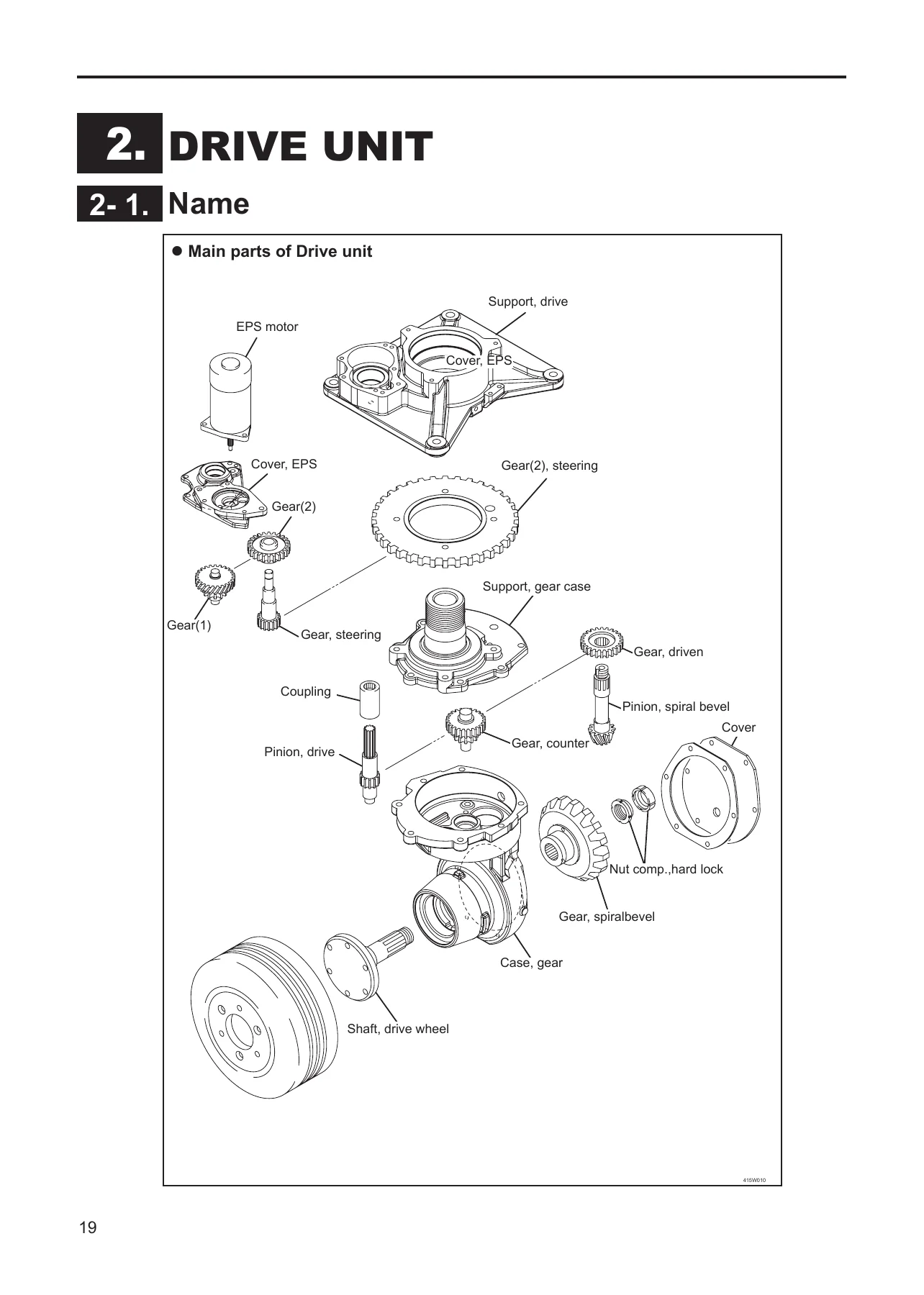
- Drive Unit – main part names, removal and installation, disassembly and reassembly, gear inspection and replacement, drive wheel inspection, troubleshooting
- Load Wheel – main part names, disassembly and reassembly, load wheel and tilt pin inspection
- Brake – brake assembly removal and installation, disassembly and reassembly, inspection, air gap adjustment, troubleshooting
- Hydraulic System – hydraulic circuit diagram
- Hydraulic Pump – removal and installation, inspection, lift speed specification, troubleshooting
- Oil Tank and Oil Piping – tank removal and reassembly, oil piping replacement precautions, oil inspection, recommended oil, oil quantity, troubleshooting
- Control Valve – removal and installation, relief pressure measurement and adjustment, troubleshooting
- Cylinder – lift cylinder location and names for Std and M mast, removal, installation and adjustment, disassembly and reassembly, cylinder and piston rod inspection, drift of lift lowering, troubleshooting
- Mast – main parts for Std mast and M mast, lift table removal, mast removal and installation, mast disassembly and reassembly, fork disassembly and reassembly, roller, side roller, back shoe, lift chain, chain bolt, chain wheel, hose pulley inspection and adjustment, fork sensor adjustment, mast inclination, slack of chain detector, troubleshooting
- Lift Table Assembly – main parts for drive front and fork front, lift table removal and installation, brake assembly, side guard, control panel installation and adjustment, brake switch adjustment, safety belt inspection, troubleshooting
- Motor – traction motor, hydraulic motor and EPS motor main parts, specifications, removal and installation, disassembly and reassembly, rotor and armature inspection, brush, brush holder and spring service, insulation testing, troubleshooting
- Control Panel Assembly – main part names, control panel, steering sub assembly and accelerator sub assembly disassembly and reassembly, pin and bushing inspection, potentiometer adjustment, troubleshooting
- Electric Parts – location and name
- Control Unit – main parts, removal and installation, disassembly and reassembly, contactor check and replacement, FET module inspection and replacement, capacitor check and replacement, fuse replacement, EPS board specification
- Fan – removal and installation
- Steering Angle Potentiometer – disassembly and reassembly, checking and adjustment
- Charger – assembly and transformer disassembly and reassembly, charger and charger switch specifications, magnetic contactor, plug and receptacle, link fuse and fuse base, transformer, diode inspection, sensor and timer inspection, voltage tap check, selection and switching, link fuse replacement
- Battery – removal and installation, electrolyte inspection and replenishment, specific gravity measurement, cleaning of cells and vent plugs
- Lift Height Encoder – disassembly and reassembly, magnet sensor adjustment
- Auto Pallet Lock – function, detecting error, warning buzzer, disassembly and reassembly, pallet lock function checking, cylinder detector, pallet detector and pallet lock potentiometer adjustment, inspection after adjustment, troubleshooting
- Service Data – standard work hours by group and job for RB10, RB15 and RBC7/9/10
- Adjustment of SICOS-AC – control board construction, travel/hydraulic board, display board, EPS board, rotary switch functions, adjustment standards list, chassis insulation, model setting, current detector, safety monitor symbol, plugging and regenerative braking force, hydraulic setting, optional setting, accelerator potentiometer adjustment, prestop/travel reduction/lift stopping height, load sensor check and adjustment, steering wheel and steering angle potentiometer adjustment, safety device checks, hour meter, turn signal lamp, cooling fan, turning speed reduction, auto power off, built-in charger
- Troubleshooting – self diagnosis function, error messages and display conditions, error history memory, I/O check and I/O port tables
- Wiring Diagrams – system wiring, body wiring, body harness, controller wiring and harness, control panel wiring and harness, accelerator wiring, table harness, mast harness, BC wiring and BC harness
Read end to end, the manual gives a technician the full working picture of the 70 Series truck rather than a single isolated procedure. The mechanical chapters are paired with the electrical and electronic material, so a fault traced through the SICOS-AC self-diagnosis screen can be followed straight into the FET module, contactor, current sensor or motor it points to. The hydraulic chapters run from the circuit diagram through the pump, control valve, cylinders and oil tank, with relief pressure and drift figures given as measurable limits. The mast and lift table chapters cover both the standard mast and the M mast, including chain tension, roller clearance, back shoe thickness and the slack of chain detector settings.
Drive Unit, Brake, Load Wheel and Motors
The drive unit chapter opens with the main part names and then walks through removal and installation, followed by the disassembly and reassembly sequence for the EPS gear set, the support and cover group, and the gear case group. Gear inspection covers wear, scoring, pitting and spline damage with replacement as a set. Drive wheel inspection gives the specific dimension and wear limit for both the RB10/15 and RBC7/9/10 trucks. The brake chapter covers the brake assembly removal, disassembly, inspection for operation, abnormal sound, heat and contamination, and the air gap adjustment to 0.2 mm. The motor chapter separates the traction motor, hydraulic motor and EPS motor, listing their types and ratings and covering rotor, armature, brush, brush holder, spring and insulation service, including the commutator repair procedure and limits.
Hydraulics: Pump, Oil Tank, Control Valve and Cylinders
The hydraulic material starts with the circuit diagram, then moves into the hydraulic pump removal and installation with the tightening torques for the U nut and fitting bolts, coupling spline lubrication, and the lift speed specification table for each model. The oil tank chapter covers tank removal for both RB and RBC, tank disassembly, recommended oils for standard and cold storage specifications, and oil quantity by model with the level gauge range. The control valve chapter explains relief pressure measurement using a damped pressure gauge, gives the relief pressure for RB10/15 and RBC7/9/10, and describes adjustment through the adjusting screw. The cylinder chapter covers the standard mast lift cylinder, the M mast first and second cylinders, the installation and adjustment procedure using the adjust bolt, and drift of lift lowering specifications per model and mast type.
Mast, Lift Table and Fork
Both the standard mast and the M mast are broken down with exploded parts views. The removal procedures for the lift table and mast assembly are given separately for each mast type, along with the shim and roller notes that must be recorded before disassembly. Inspection and adjustment covers mast and lift table channel cracks, back shoe thickness and wear limit, lift chain elongation measured over 20 links with the elevation limit and pitch for each chain type, chain bolt condition, chain wheel and hose pulley wear, mast roller and lift roller clearance, side roller adjustment, fork leveling, opening and bending limits, fork shaft wear, the fork sensor adjustment on RBC trucks, lift chain deflection, mast inclination, and the slack of chain detector setup for the standard mast and for both the second-side and first-side chains of the M mast.
Control Panel, Control Unit and Battery
The control panel assembly chapter covers the complete panel, the steering sub assembly and the accelerator sub assembly, with the pin and bushing wear limits and the potentiometer adjustment procedure. The control unit chapter identifies the current sensors, FET modules, MPU board, heat sink, condenser bank, contactor, EPS board and fuses, and then explains contactor inspection and replacement, FET module continuity testing at the listed test points, capacitor appearance and tester checks, capacitor discharging with a resistor, and fuse replacement with the correct capacity. The battery chapter covers removal and installation on RB and RBC, electrolyte level checking against the float indicator, replenishing with refined or distilled water using the siphon method, and specific gravity measurement and temperature conversion.
SICOS-AC Adjustment, Diagnostics and Wiring
The SICOS-AC section explains how the display board, travel/hydraulic board and EPS board exchange data, what each rotary switch position on the display board selects, and then gives step-by-step adjustment procedures for chassis insulation, model setting, travel and hydraulic motor current checking, monitoring symbol settings, plugging and regenerative braking strength, hydraulic speed limits by travel speed band, optional settings, the accelerator potentiometer, prestop and lift stop heights, and the load sensor including unladen first and second stage, laden, overload and net weight zeroing. The safety device checks cover the safety guard, travel and hydraulic neutral safety, fork sensor, slack of chain detection and the ceiling detector. Troubleshooting lists the self-diagnosis symbols and error numbers with probable causes, error history memory 1 and 2, memory initialization, and the I/O check mode with full I/O port tables for the travel, hydraulic, display and EPS CPUs. The wiring section finishes with system, body, controller, control panel, accelerator, table, mast and charger diagrams and harness pinouts.
Service Data and Standard Work Hours
The service data chapter sets out standard work hours by group and job for RB10, RB15 and RBC7/9/10, covering maintenance replacements such as drive gear oil and hydraulic oil, frame covers, potentiometers, drive assembly, steering gear, load wheels, brake system, brake linkage, oil tank, hydraulic pump, frame piping, control valve, lift cylinders, mast, lift table assembly, auto pallet lock, traction motor, hydraulic motor, EPS motor, control unit, control panel, electric power steering and battery work. This lets a shop quote and schedule jobs against factory time allowances instead of guessing.
Who This Manual Suits
This Nichiyu 70 Series service manual suits forklift service technicians, fleet maintenance departments, independent workshops and owners who maintain their own RB10-70, RB15-70, RBC7-70, RBC9-70 or RBC10-70 truck. It is written for people with the tools and background to work safely on electric lift trucks, and it states plainly that maintenance and repair without adequate knowledge can cause accidents. Safety labels and their locations, cautions on jacking and supporting the truck, disconnecting the battery plug, discharging control unit capacitors, capping hydraulic lines against dust, and using the correct tightening torque are all part of the text rather than an afterthought.
Put the Nichiyu RB10-70 RB15-70 RBC7-70 RBC9-70 RBC10-70 Service Manual to Work
With this manual on hand you can strip and rebuild a drive unit, set a brake air gap, measure and correct relief pressure, replace lift cylinder packings, adjust chain tension and roller clearance, test FET modules and capacitors, replace a contactor or fuse, work through the SICOS-AC adjustment screens, read the self-diagnosis error numbers and follow a fault into the wiring diagram that matches the truck in front of you. Correct procedures and the correct specifications are what keep an electric lift truck safe, keep repeat failures from coming back, and keep a repair from turning into a second repair. The Nichiyu 70 Series service manual puts the factory figures, the tightening torques, the wear limits and the diagnostic tables in one place so the job is done once and done right.
IMAGES PREVIEW
Delivery is instant. This is a downloadable PDF – no shipping, no waiting for a parcel, no torn pages in a binder. Open it on a laptop, tablet or phone in the workshop, print the pages for the job at hand, and keep the file for the next truck that comes in. Order now and the Nichiyu RB10-70, RB15-70, RBC7-70, RBC9-70 and RBC10-70 service manual is ready to download.
Reviews
There are no reviews yet.