
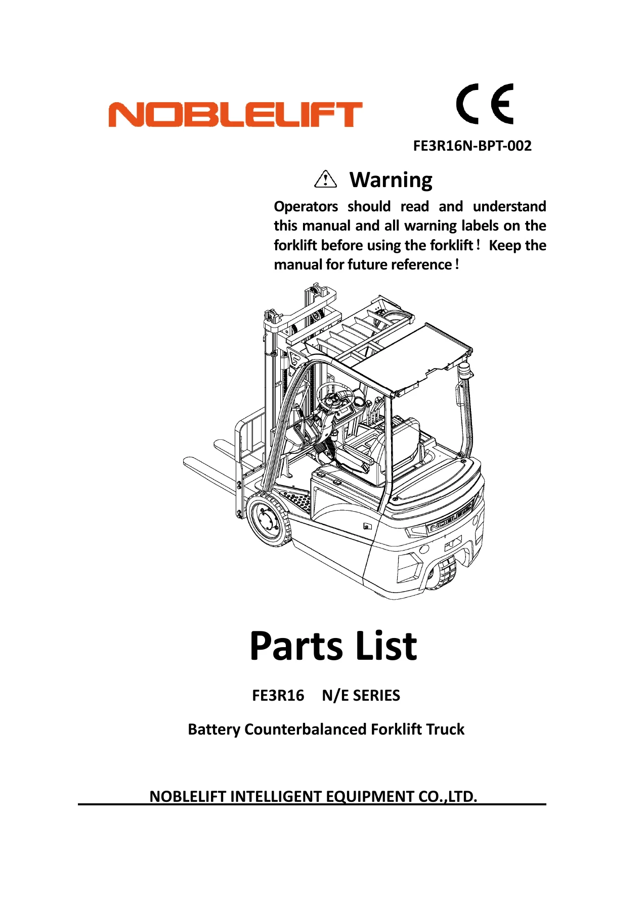
Noblelift FE3R16 N/E Series Battery Forklift Parts List Catalog – FE3R16N-BPT-002
Original price was: $69.95.$39.95Current price is: $39.95.
Complete 121-page spare parts catalog for Noblelift FE3R16N and FE3R16E battery counterbalanced forklift trucks. 44 illustrated figures with exploded views and parts tables covering frame, drive steering, hydraulics, mast assemblies, electrical system, and labels. Instant PDF download.
Description
Noblelift FE3R16 N/E Series Battery Forklift Parts List — Complete Spare Parts Catalog (FE3R16N-BPT-002)
When a forklift goes down, every hour of downtime cuts into your operation. This Noblelift FE3R16 N/E Series parts list gives you the exact part numbers, quantities, and exploded illustrations needed to identify and order the right spare components for your FE3R16N or FE3R16E battery counterbalanced forklift truck. Published under document number FE3R16N-BPT-002, this 121-page PDF catalog covers the complete machine — from frame and drive steering to mast assemblies, hydraulic pipelines, electrical controls, and even the safety labels. Every figure pairs a detailed exploded view with a corresponding parts table, so you can trace every component back to its reference number and order with confidence.
File Details
- Manual Type: Parts List / Spare Parts Catalog
- Brand: Noblelift
- Model: FE3R16 N/E Series (FE3R16N, FE3R16E)
- Document Number: FE3R16N-BPT-002
- Language: English
- Page Count: 121
- File Format: PDF
- Date: Sep, 2018
Chapters Covered
This parts list is organized into 44 figures, each dedicated to a specific assembly or system of the FE3R16 N/E Series forklift:
- Frame Assembly (Figure 1)
- Roof Support and Installation (Figure 2)
- Drive Steering System (Figure 3)
- Bottom Assembly (Figure 4)
- Battery Box Cover (Figure 5)
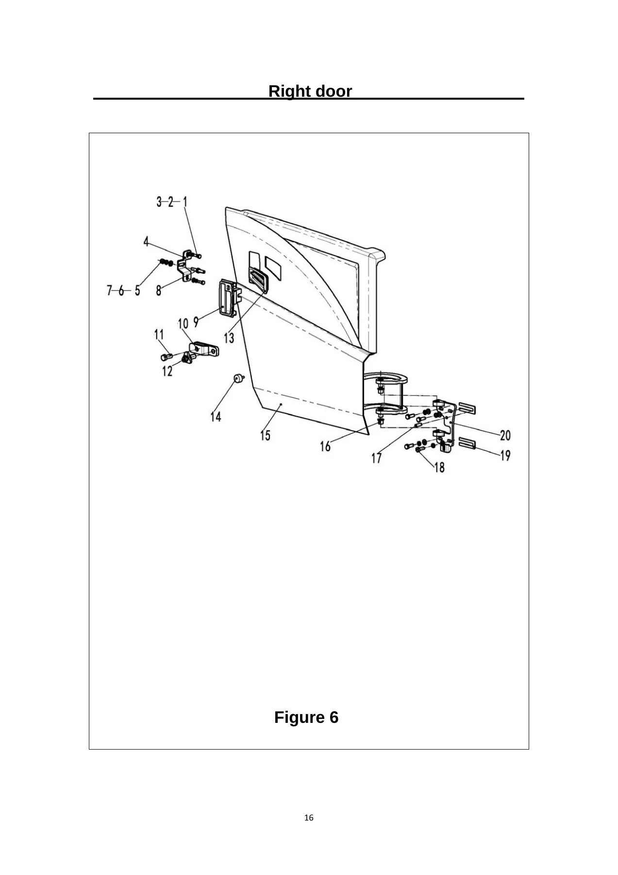
- Right Door (Figure 6)
- Left Plate (Figure 7)
- Valve Cover (Figure 8)
- Balanced Reassembly (Figure 9)
- Corner Sensor — Optional (Figure 10)
- Lifting Motor and Installation (Figure 11)
- Foot Brake Control (Figure 12)
- Foot Brake Control Line (Figure 13)
- Hand Brake Control (Figure 14)
- Multiple Directional Control Valve — Bigeminy, Trigeminy, Four Joint (Figures 15–17)
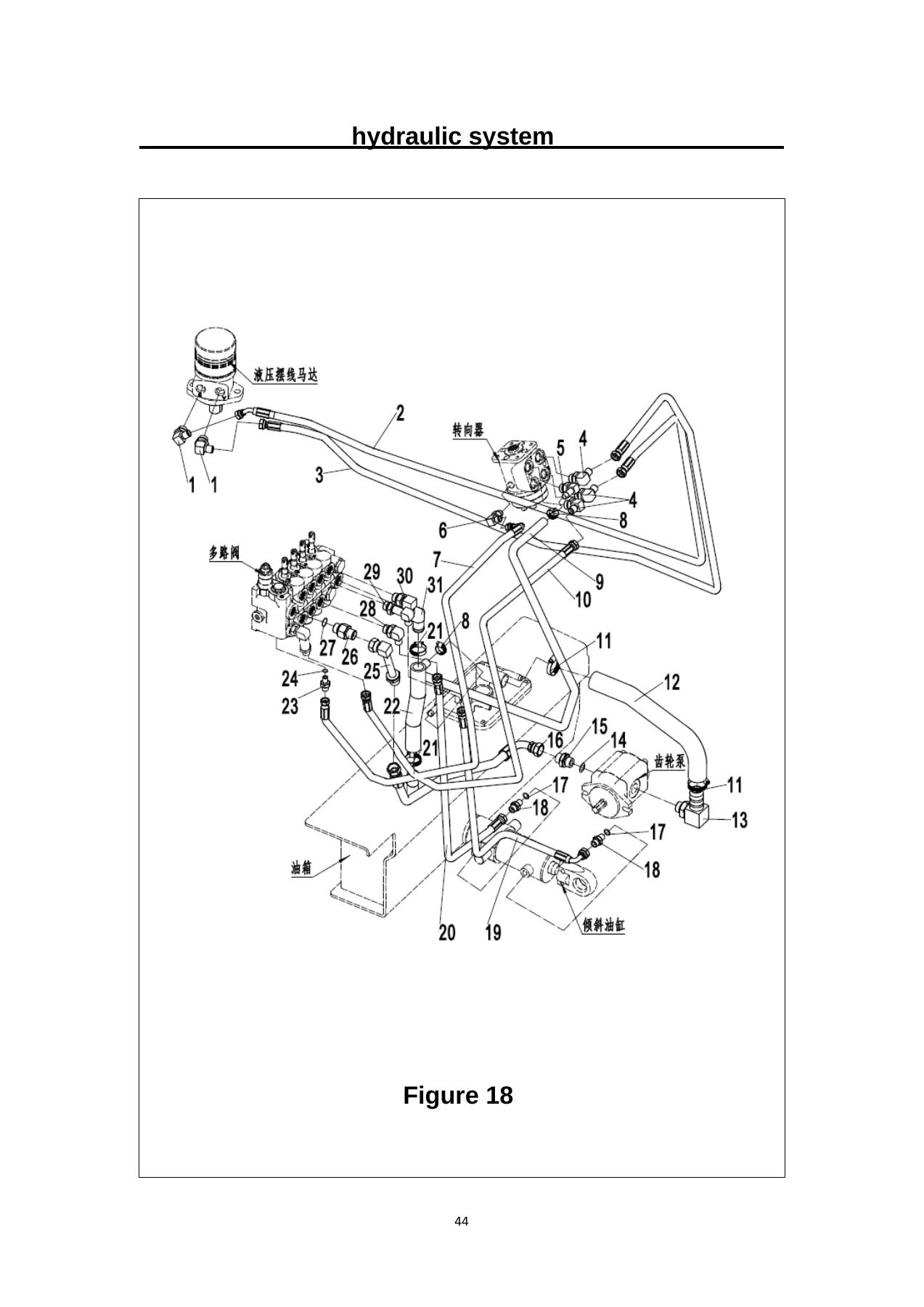
- Hydraulic System (Figure 18)
- Working Tank and Installation (Figure 19)
- Mast Lifting Pipeline — Standard, Two Stage Full Free, Three Stage Full Free (Figures 20–22)
- Side Shifter and Pipeline Installation — Standard, Two Stage Full Free, Three Stage Full Free (Figures 23–25)
- Fork (Figure 26)
- Fork Carrier — Standard, Two Stage Full Free, Three Stage Full Free (Figures 27–29)
- Mast — Standard, Two Stage Full Free, Three Stage Full Free (Figures 30–32)
- Lifting Cylinder — Standard Mast (Figure 33)
- Short Lifting Cylinder — Two Stage Full Free, Three Stage Full Free (Figures 34, 36)
- Lifting Cylinder — Two Stage Full Free, Three Stage Full Free (Figures 35, 37)
- Tilted Cylinder (Figure 38)
- Electrical System (Figure 39)
- Electronic Control Element — Curtis (Figure 40)
- Electronic Control Element — Inmotion (Figure 41)
- Power Connector Assembly (Figure 42)
- Sign Installation (Figure 43)
- Data Nameplate (Figure 44)
Frame, Body and Cab Components
The frame assembly section (Figure 1) covers the structural components including brackets, mounting boards, welding assemblies, and the fasteners that hold the chassis together — M6, M8, and M14 bolts, washers, and nuts are all specified with their standard part numbers. Figures 2 and 4 through 9 break down the roof support structure, bottom pedal assembly, battery box cover with its hinges and gas springs, the right side door with its lock and vent, the left side plate, valve cover, and the counterweight assembly. The counterweight section includes separate part numbers for the FE3R13 and FE3R16 variants, along with adjustment pads, washers, and mounting hardware.
Drive and Steering System
Figure 3 covers the complete drive steering system, including the cycloidal motor, gearbox options (South Central and Xinchang Hawk), AC motors (YDQ5-4-9200 and JXQ-5-N), encoder, rear wheel assembly (18X7-8 solid and environmentally friendly variants), rims, and all associated bolts and washers. This section is critical for anyone servicing the drivetrain or replacing steering components on the FE3R16 N/E Series.
Brake Systems
Figures 12 through 14 detail the foot brake control assembly, brake control line, and hand brake control. The foot brake assembly includes the brake pump, pedal, pull spring, pin shafts, and limit plate. The brake line section covers hydraulic pipes, hoses, oil cup, and joint fittings. The hand brake control is a compact section with the hand brake lever and mounting hardware.
Hydraulic System and Control Valves
The hydraulic sections are among the most detailed in this parts list. Figures 15 through 17 cover the multiple directional control valve in bigeminy (two-combined), trigeminy (three-combined), and four-joint configurations, complete with joystick assemblies, handles, shafts, and connection rods. Figure 18 is the master hydraulic system diagram, showing the oil return hose, hydraulic pipe assemblies, joints, O-rings, and the multiway valve feed pipe. Figure 19 covers the working tank with its cover board, mesh filter, respirator, and oil discharge plug. These sections are essential for troubleshooting hydraulic issues and ordering the correct hoses, fittings, and valves.
Mast, Lifting and Side Shifter Components
Figures 20 through 25 and 30 through 37 form the core of the lifting system documentation. Mast lifting pipelines are covered in three configurations: standard mast, two stage full free, and three stage full free, with hydraulic pipe assemblies specified by length (L=1350 through L=5400) and lifting height (H=2500 through H=5000). The side shifter and pipeline installation sections follow the same three-configuration pattern, with external and internal groove weldments, pulleys, hose fixing blocks, and mounting plates. The mast sections themselves (Figures 30–32) cover inner, middle, and outer mast options for standard, two stage full free, and three stage full free configurations. Lifting cylinders, short lifting cylinders, and tilted cylinders are detailed in Figures 33 through 38, including cylinder dimensions (Φ32xΦ40, Φ70xΦ55), seal repair kits, lifting chains (LH1223 and LH1266 series), sprocket bearings, and all internal components.
Forks and Fork Carriers
Figure 26 covers the hook type II A forks in multiple lengths — 920mm, 950mm, 1070mm, 1150mm, 1220mm, 1370mm, and 1520mm — with fork body and raising assembly components. Figures 27 through 29 detail the fork carriers for standard mast, two stage full free, and three stage full free configurations, including the block shelf soldering, compound rollers, shaft elastic rings, and mounting bolts.
Electrical System and Electronic Controls
Figure 39 is the master electrical system diagram, covering microswitches, key switch, horn, emergency stop switch, instrument panels, converters (DC48V to 24V, DC24V to 5V), body harnesses, chargers (SN48V55A in multiple regional variants), and the full power cord bundle. Figures 40 and 41 detail the electronic control elements for both Curtis and Inmotion systems, including controllers (1232E, 1232SE, ACS48S-350C), fuse boxes, contactors, relays, fuses, and accelerator assemblies. Figure 42 covers the power connector assembly with battery connection cables and power cable. These sections are indispensable for diagnosing electrical faults and replacing control components.
Labels, Decals and Identification
Figure 43 covers the sign installation with 16 label types, including safety labels, warning stickers, NOBLELIFT branding, battery maintenance tips, hydraulic oil labels, hoisting labels, and anti-rollover markings. Figure 44 details the data nameplate, rivets, side shift weight loss sticker, and load curve sticker. These are essential for maintaining compliance and restoring the truck’s original appearance after repairs.
Why This Parts List Matters
Ordering the wrong part for a forklift isn’t just expensive — it costs time. A misidentified hydraulic fitting or an incorrect seal kit can keep your FE3R16N out of service for days while you wait for a replacement. This parts list eliminates that risk by giving you the exact part number, reference number, and quantity for every component on the truck. Whether you’re rebuilding a mast cylinder, replacing a burnt-out controller, or simply refreshing worn-out brake components, the exploded views and parts tables give you the visual and numerical information you need to order correctly the first time.
The catalog also distinguishes between standard, two stage full free, and three stage full free mast configurations throughout the lifting sections, so you can match parts to your specific truck setup. Optional and regional variants — like the corner sensor, solid vs. environmentally friendly tires, and different charger configurations — are clearly marked, preventing ordering mistakes on those items as well.
IMAGES PREVIEW
Instant PDF Delivery — No Shipping, No Waiting
This Noblelift FE3R16 N/E Series parts list is delivered as an instant PDF download. There’s no shipping, no waiting for a physical book to arrive, and no risk of a damaged or lost package. Once your order is complete, you can download the file immediately and start looking up part numbers right away. The PDF works on any device — desktop, laptop, tablet, or smartphone — and you can print the specific pages you need for the workshop or parts counter. Keep it on your computer for quick reference, or print the whole thing and keep it in a binder next to your service area. Either way, you’ll have the complete FE3R16N-BPT-002 parts catalog at your fingertips whenever you need it.
Reviews
There are no reviews yet.