O and K WHEEL LOADER MODEL L45-4500Z-TB126 PARTS MANUAL – PDF DOWNLOAD
Original price was: $76.95.$21.95Current price is: $21.95.
O and K WHEEL LOADER MODEL L45-4500Z-TB126 PARTS MANUAL – PDF DOWNLOAD
Description
O and K WHEEL LOADER MODEL L45-4500Z-TB126 PARTS MANUAL – PDF DOWNLOAD
FILE DETAILS:
O and K WHEEL LOADER MODEL L45-4500Z-TB126 PARTS MANUAL – PDF DOWNLOAD
Format: PDF
Language: English
DESCRIPTION:
O and K WHEEL LOADER MODEL L45-4500Z-TB126 PARTS MANUAL – PDF DOWNLOAD
INTRODUCTION:
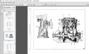
- This manual illustrates and identifies maintenance parts for the Model 4500Z loader, to enable you to determine the part number and name assigned to the part you wish to order. Ordering by proper part number and name will help ensure the receipt of the proper part for the first time without time-consuming exchanges of correspondence or other annoying delays.
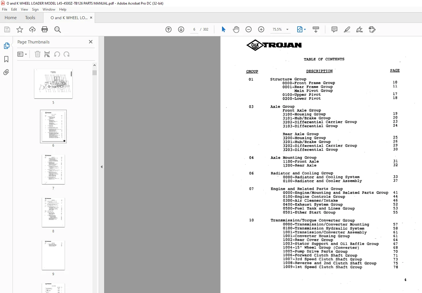
- An index is provided in the front of this manual to help you determine which illustration contains the part you want to order. Determine the basic system or assembly in which the part is used, and find this system or assembly in the Index. It will reference the pages which illustrate and list the part.
- This manual contains the latest information available at the time of printing. However, at the discretion of O & K Trojan Industries. its contents are subject’ to change .without notice. This reservation is in keeping with the Company’s policy of constant progressive improvement and refinement of all of our products. As a result of such policy, certain changes may be made from time to time which will not be covered in this manual.
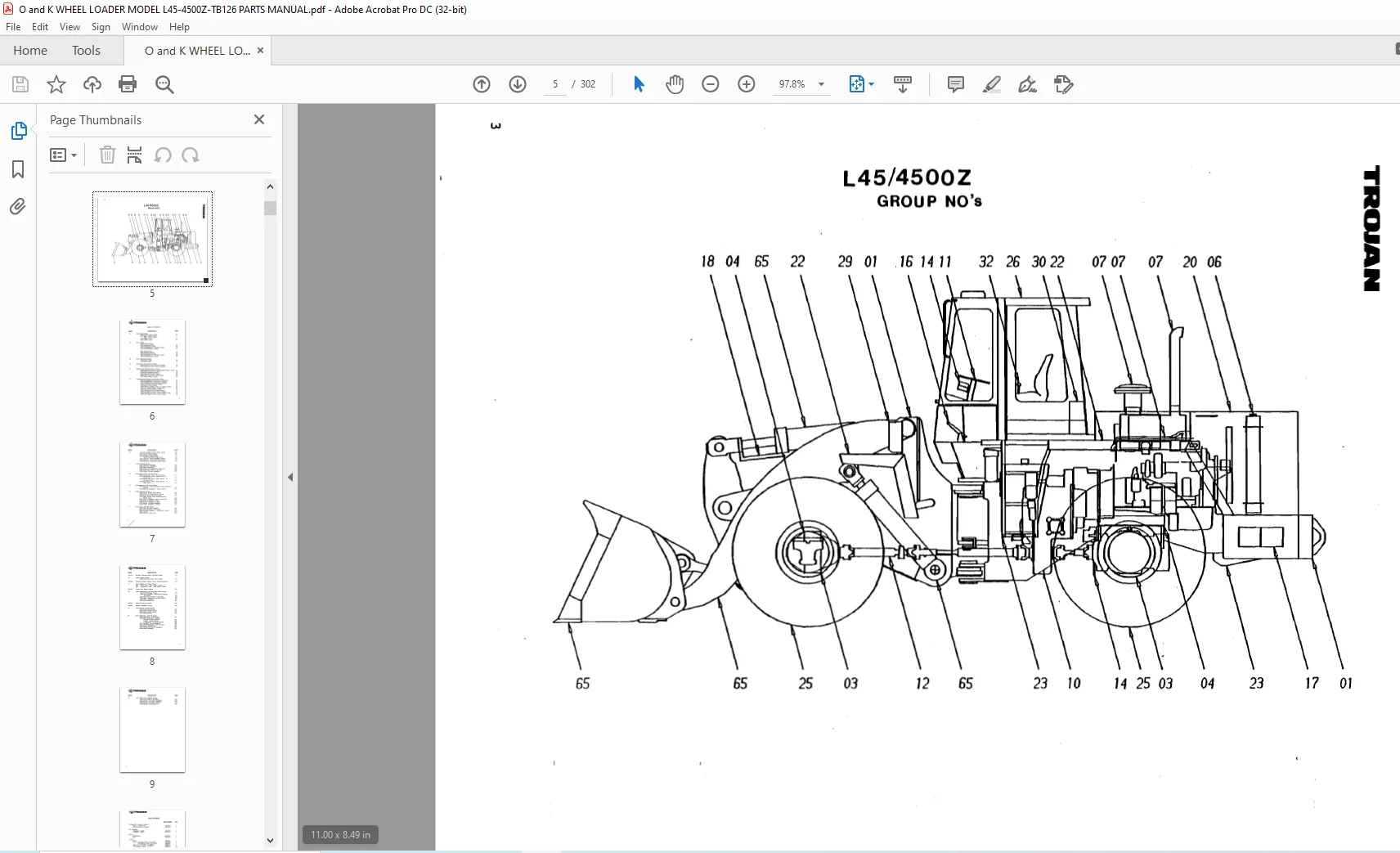
- This manual has been indexed by group numbers, which identifies the « area of the machine that requires servicing. The first two digits in the group numbers indicates the area of the machine.
Example: Group 32 05 01
32 – Indicates – Hydraulic System
05 – Indicates — Hydraulic Tank Assembly
01 – Indicates – Hydraulic Filter
These group numbers are for easy reference only.
The group numbers are provided for easy access to the area in which the part is used. Find the basic group number, turn to the illustration and find the part (item number) you want to order.
Because we are constantly upgrading our equipment, it is necessary“ that the SERIAL NUMBER of your machine accompany every repair parts order. To assure the receipt of the proper part, it is essential that the following information be included with your parts order:
- MACHINE MODEL NUMBER
- MACHINE SERIAL NUMBER
- PART NUMBER OF THE DESIRED PART
- PART NAME OF THE DESIRED PART
- QUANTITY OF ITEMS WANTED
- NAME AND ADDRESS TO WHICH PART SHOULD BE SENT
USE ONLY PARTS WHICH ARE AUTHORIZED.BY O a K TROJAN INDUSTRIES TO ENSURE THAT’ ORIGINAL“ DEPENDABILITY AND, PERFORMANCE WILL BE MAINTAINED.
IMAGES PREVIEW OF THE MANUAL:
TABLE OF CONTENTS:
O and K WHEEL LOADER MODEL L45-4500Z-TB126 PARTS MANUAL – PDF DOWNLOAD
1010-4th Speed Clutch Shaft Group
loll-Idler Shaft Group
1012-Output Shaft Group
1013-Pressure Regulating
Valve/Charging Pump Group
1014-Control valve Assembly Group
1015-Control Valve Housing Group
1015-Backing Plate/Ring Gear Group
Steer System Group
0000-EydraulicSystem
0001-Cylinder Assembly
0002-Pump Assembly
0003-Servostat Assembly (Orbitrol)
0004-Steering Wheel 5 Hub Kit
0005-Steer Column Assembly
Universal Joint Installation
0000-Universal Joint Installation
0100-Universal Joint Assy-Pillow to
Front Axle
0200-Universal Joint Assy.-Trans. to
Pillow Block
0300-Universal Joint Assy.-Trans. to
Rear Axle
Transmission Controls Group
0000-Electric Shift/Signal Light Switch 8
Wiring
0100-Switch Assembly, Trans. Shift
Brake System Group
0001-Front Brake Line Group
OOOZ-Control Distribution Group
0003-Flow Distribution GrOup
0004-Rear Brake Line Group/Parking
Brake Disc
0005-Valve Assembly, Multi-Function
0006-Pump Assembly; Brake
0007-Filter Assembly, Servo
0008-Brake Caliper Assembly
0009-Pedal Assembly, Brake
Electrical System Group
0000-Main Wiring Diagram
0001-Instruments & Switches
0002-Wiring Diagram – Instrument Panel
0003-Lights
0004-Battery Mounting
0010-4th Speed Clutch Shaft Group
1011-Idler Shaft Group
1012-Output Shaft Group
1013-Pressure Regulating
valve/Charging Pump Group
1014-Control Valve Assembly Group
1015-Control valve Housing Group -.
1016-Backing Plate/Ring Gear Group
Steer System Group
0000-HydraulicSystem
0001-Cylinder Assembly
0002-Pump Assembly
0003-Servostat Assembly (Orbitrol)
0004-Steering Wheel 8 Hub Kit
0005-Steer Column Assembly
Universal Joint Installation
0000-Universal Joint Installation
0100-Universa1 Joint Assy—Pillow to
Front Axle
0200-Universal Joind Assy.-Trans. to
Pillow Block
0300-Universal Joint Assy.-Trans. to .
Rear Axle
Transmission Controls Group
0000-Electric Shift/Signal Light Switch
Wiring. .
0100-Switch Assembly, Trans. Shift
Brake System Group ‘
0001-Front Brake Line Group
0002-Control Distribution Group
0003-Flow Distribution Group
0004-Rear Brake Line Group/Parking
Brake Disc
0005-Valve Assembly, Multi-Function
0006-Pump Assembly, Brake
0007-Filter Assembly, Servo
0008-Brake Caliper Assembly
0009-Pedal Assembly, Brake.
Electrical System Group
0000-Main Wiring Diagram
0001-Instruments 8 Switches
0002-Wiring Diagram – Instrument Panel
0003-Lights
0004-Battery Mounting
Bucket Leveler/Hoist Kickout Group
Sheet Metal GRoup
0000-Hood and Rear Cowl Group
Fenders/Lower Engine Panel Group/Handrails
Fuel/Hydraulic Tanks Group
Ref – Fuel Tank – See Group 070500
Ref – Hydraulic Tank – See Group 320500
Tires and Wheels Group
Cab/Floorplates and Related Parts Group
1400-Floorplates Group
1600-Cab Assembly, Windshield Washer .
and Wiper
1601-Cab Door/Window 8 Hardware
2200-Seat Installation/Seat Belts
2201-Seat Assembly
3500-Cab Acoustics
Identification Group
Heater Assembly Group
Lubrication System Group
0001-Lift Arm Group
0002-Front Frame Group
0003-Rear Frame Group
0004-AxleTrunion
Main Hydraulic System Group
0500-Hydraulic Tank Steps
4000-Main Hydraulic System
A-Front’Frame System
B-Rear Frame System
C-Hydraulic Cooling System
4001-Contgpl Valve Assembly
4002-ValvegAssembly Flow Divider
4003-Servo Hydraulics
4005-Unloading Valve Assembly
4006-Pump Assembly
Lift Arms and Linkage Group
0000-Lift Arms 8 Linkage
0001-Bucket Cylinder Assembly
0002—Hoist Cylinder Assembly
9000-Bucket Assembly Group
9100-Bucket Attachments
O AND K WHEEL LOADER MODEL L45-4500Z-TB126 PARTS MANUAL – PDF DOWNLOAD:
PLEASE NOTE:
- This is the SAME exact manual used by your dealers to fix your vehicle.
- The same can be yours in the next 2-3 mins as you will be directed to the download page immediately after paying for the manual.
- Any queries / doubts regarding your purchase, please feel free to contact [email protected]