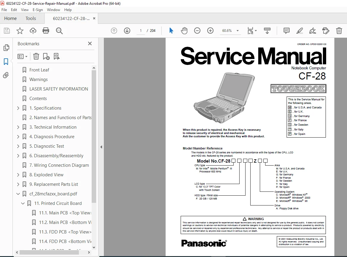
Panasonic CF-28 Toughbook Rugged Laptop Service Manual PDF
Original price was: $95.00.$16.95Current price is: $16.95.
Complete factory service manual for Panasonic CF-28 Toughbook rugged notebook computers with Intel Pentium III processor. Includes detailed specifications, diagnostic procedures, POST error codes, disassembly instructions, wiring diagrams, exploded views, replacement parts lists, and troubleshooting guides. Covers all regional variants with touchscreen, modem, and multimedia configurations. Essential technical documentation for Toughbook technicians and rugged laptop repair professionals. Instant PDF download.
Description
Panasonic CF-28 Toughbook Rugged Laptop Service Manual Repair Guide PDF DOWNLOAD
Description
Panasonic CF-28 Toughbook Rugged Notebook Computer Complete Service Manual – Professional Technical Documentation
This comprehensive Panasonic CF-28 service manual PDF provides complete service information, diagnostic procedures, disassembly instructions, and parts identification for the Panasonic CF-28 Toughbook series rugged notebook computers. This professional-grade Toughbook repair guide covers all regional variants with detailed technical specifications, troubleshooting procedures, and maintenance instructions essential for rugged laptop service technicians and computer repair professionals.
File Details
- Manual Name: Panasonic CF-28 Toughbook Service Repair Manual
- Models Covered: CF-28 Series (All configurations)
- Manufacturer: Matsushita Electric Industrial Co., Ltd. (Panasonic)
- Order Number: CPD0102001C0
- Total Pages: 204 pages
- PDF Quality: High-quality optimized factory original
- Language: English (with multilingual safety warnings)
- Publication Date: February 2001 (Updated May 2005)
- Document Format: Letter size
Product Specifications Overview
System Configurations:
- CPU: Intel® Mobile Pentium® III Processor 600 MHz
- Display: 13.3″ TFT Color LCD with Touchscreen capability
- Memory: 128MB RAM (expandable)
- Storage: 20GB Hard Disk Drive
- Operating Systems: Windows NT®, Windows® 2000, Windows® 98
- Keyboard: 87 keys (US), 88 keys (European)
- Pointing Devices: Touch Pad and Touchscreen (anti-reflection, finger and stylus capable)
Regional Variants Covered:
- M: USA and Canada
- E: United Kingdom
- G: Germany
- F: France
- S: Sweden
- T: Italy
- P: Spain
Key Features:
- Rugged Design: Durable construction for harsh environments
- Touchscreen: Anti-reflection with finger and stylus input
- Internal Modem: 56 Kbps data (V.90 & K56flex), 14.4 Kbps FAX
- PC Card Slots: Two Type I/II or one Type III
- Multimedia: 16-bit 44.1 KHz PCM/FM sound
- Battery: Li-ion 11.1V, 5.4Ah (3.5-5.2 hours operating time)
- Expansion: Dedicated 80-pin expansion bus connector
Connectivity:
- Parallel port (DB-25 female)
- External display port (Mini DB-15 female)
- Serial port (DB-9 male)
- USB port (4-pin)
- IrDA 1.1 infrared (4 Mbps)
- External keyboard/mouse port (Mini DIN 6-pin)
- Microphone and headphone jacks (3.5mm)
Complete Table of Contents
Section 1: Specifications (Pages 1-1 to 1-2)
- Main Specifications
- Model number reference system
- CPU type identification
- LCD specifications
- Operating system variants
- HDD and RAM configurations
- Drive options
- Other Specifications
- Keyboard layout by region
- Floppy disk drive (720KB/1.44MB)
- PC Card slots and power ratings
- All interface specifications
- Internal modem specifications
- Pointing device details
- Audio specifications
- Battery specifications:
- Operating time: 3.5 to 5.2 hours
- Charging time: 3.0 hours (power off), 5.5 hours (power on)
- AC adapter: 100-240V AC input, 15.6V DC output
- Environmental specifications
- Operating: 5°C to 35°C (41°F to 95°F), 30-80% humidity
- Storage: -20°C to 60°C (-4°F to 140°F)
Section 2: Name and Functions of Parts (Pages 2-1 to 2-2)
- External Components Identification
- Front panel controls and indicators
- Side panel ports and connectors
- Rear panel interfaces
- Bottom panel access points
- Internal Components Location
- Main PCB layout
- Expansion slots
- Battery compartment
- Multimedia pocket
- Handle assembly
Section 3: Technical Information (Pages 3-1 to 3-4)
- 3.1 System Overview
- Architecture description
- Component interconnections
- Data flow diagram
- Power distribution
- 3.2 System Memory Map
- Memory address allocation
- RAM configuration
- ROM addresses
- Video memory mapping
- 3.3 I/O Address Map
- Input/output port assignments
- Device addressing
- IRQ and DMA channels
Section 4: Diagnosis Procedure (Pages 4-1 to 4-12)
- 4.1 Basic Procedures
- Initial diagnostic steps
- Visual inspection checklist
- Power-on verification
- Pre-diagnostic setup
- 4.2 Power-On Self Test (Boot Check)
- POST sequence explanation
- BIOS initialization
- Hardware detection process
- Boot sequence verification
- 4.3 List of Error Codes
- Complete POST error code table
- BIOS beep codes
- Error message interpretation
- Critical vs. non-critical errors
- 4.4 Diagnosis Map
- Systematic troubleshooting flowcharts:
- No power conditions
- Display problems
- Keyboard/touchpad failures
- Hard drive issues
- Memory errors
- PC card problems
- Modem failures
- Sound system faults
- Battery/charging issues
- Touchscreen malfunctions
- Systematic troubleshooting flowcharts:
Section 5: Diagnostic Test (Pages 5-1 to 5-15)
- 5.1 Diagnostic Test Procedure
- Built-in Diagnostic Software
- Accessing diagnostic mode
- Test menu navigation
- Component testing procedures:
- LCD test patterns
- Keyboard test
- Touchpad calibration
- Touchscreen calibration
- Hard drive test
- Memory test
- Floppy drive test
- CD/DVD drive test (if equipped)
- Sound test
- Modem test
- PC card slot test
- Battery test
- Port loopback tests
- Built-in Diagnostic Software
- 5.2 Error Messages
- Diagnostic error code listing
- Error description and meanings
- Recommended corrective actions
- Component replacement criteria
Section 6: Disassembly/Reassembly (Pages 6-1 to 6-6)
IMPORTANT: Access Key required for security release
- 6.1 Removing the Battery Pack
- Battery release mechanism
- Safety precautions
- Reinstallation procedure
- 6.2 Removing the HDD Unit
- Hard drive bay access
- Connector disconnection
- Drive removal steps
- Installation alignment
- 6.3 Removing Unit from Multimedia Pocket
- Optical drive removal
- Floppy drive removal
- Device bay module service
- 6.4 Removing the Keyboard
- Keyboard release tabs
- Ribbon cable disconnection
- Proper handling techniques
- 6.5 Removing the Display Unit
- Hinge cover removal
- Display cable routing
- LCD assembly separation
- 6.6 Removing the RAM Card
- Memory slot access
- SO-DIMM removal procedure
- ESD precautions
- 6.7 Removing Lower Casing and Handle
- Bottom cover screw locations
- Handle assembly removal
- Reassembly alignment
- 6.8 Removing the I/O Board
- Port board access
- Connector identification
- Board replacement
- 6.9 Removing the Modem Board
- Modem card location
- Phone jack disconnection
- Card replacement
- 6.10 Removing the MP Connection Unit
- Multimedia pocket connector
- Cable routing
- 6.11 Removing the Main PCB
- Motherboard removal sequence
- All connector locations
- CPU and chipset access
- 6.12 Removing the Touch Pad Unit
- Touchpad assembly removal
- Cable routing
- Calibration after replacement
- 6.13 Removing PCMCIA CN (PC Card Slot)
- Card slot assembly removal
- Connector replacement
- 6.14 Removing RTC Battery
- CMOS battery location
- Coin cell replacement (3.0V lithium)
- BIOS settings reset
- 6.15 Removing Inverter, Touch Screen PCB, and TS13 PCB
- Display backlight inverter
- Touchscreen controller board
- LCD control electronics
- 6.16 Removing LCD and Touch Screen
- Display panel separation
- Touchscreen digitizer removal
- Panel handling precautions
Section 7: Wiring Connection Diagram (Page 7-1)
- Complete Internal Wiring Schematic
- Power distribution diagram
- Signal cable routing
- Connector pinout specifications
- Ground connections
- Shielding requirements
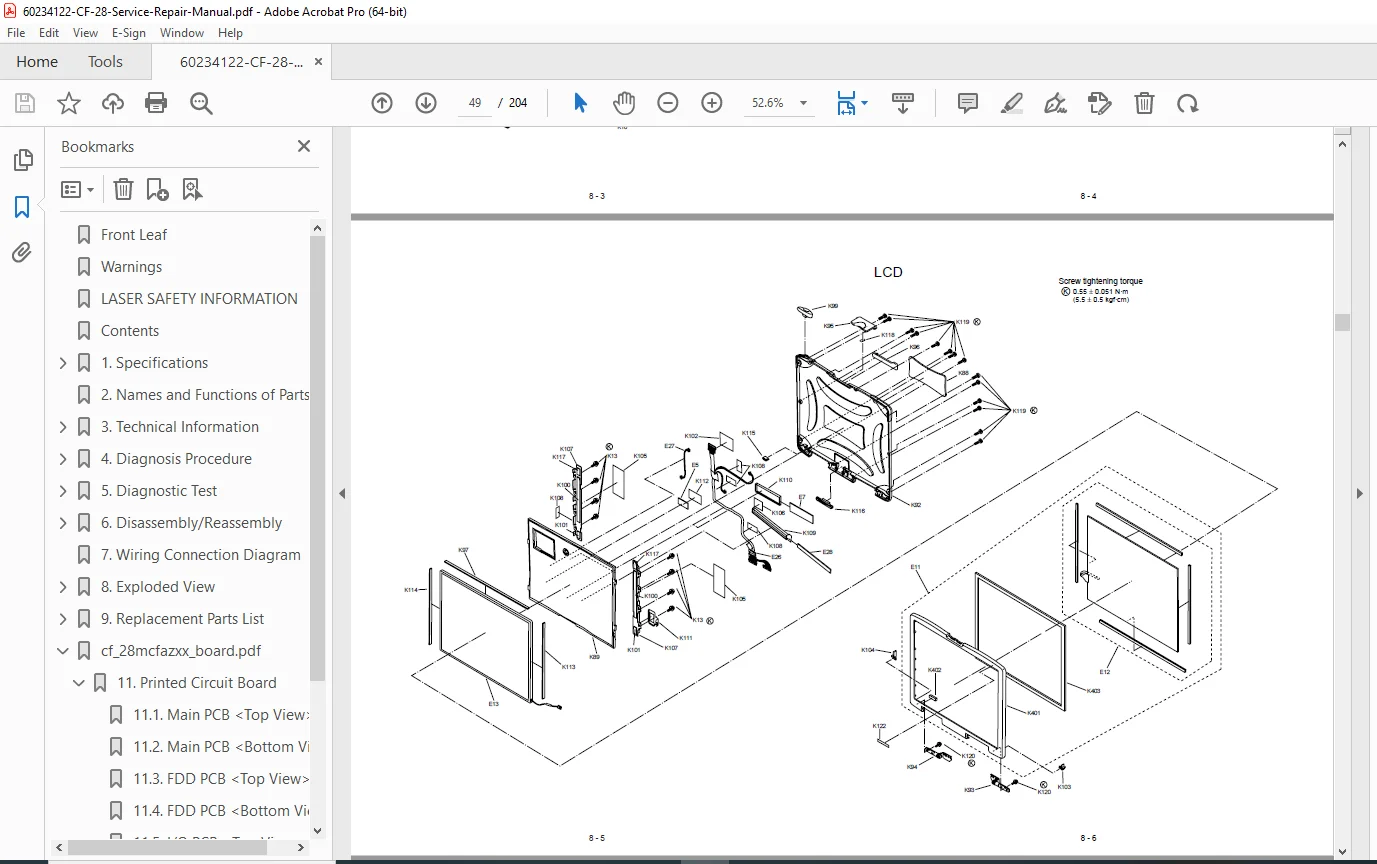
Section 8: Exploded Views (Pages 8-1 to 8-6)
- Detailed Exploded Diagrams:
- Complete unit breakdown
- Assembly sequence reference
- Screw location and type identification
- Parts relationship visualization
- Subassembly details
Section 9: Replacement Parts List (Pages 9-1 to 9-10)
- Comprehensive Parts Catalog:
- Part numbers and descriptions
- Component illustrations
- Quantity per unit
- Assembly reference numbers
- Compatible part alternatives
- Ordering information
Important Safety Information
Lithium Battery Warning:
- Danger of explosion if incorrectly replaced
- Replace only with same or equivalent type
- Proper disposal required per manufacturer instructions
- Multilingual warnings included (English, German, French)
Laser Safety:
- Class 1 LASER Product certification
- DHHS 21 CFR Subchapter J compliant
- EN60825/IEC 825 compliant
- No hazardous laser radiation under normal operation
- DVD: 658 ± 8 nm wavelength
- CD: 775-815 nm wavelength
Service Technician Warnings:
- Designed for experienced repair technicians only
- Requires proper training and tools
- Access Key required for security release
- Risk of serious injury or death if improperly serviced
Key Technical Features
Rugged Construction:
- Designed for harsh environments
- Durable housing and shock-resistant design
- Sealed keyboard and touchpad
- Reinforced LCD panel
- Drop-resistant engineering
Touchscreen Technology:
- Anti-reflection coating
- Finger and stylus input capable
- Integrated digitizer
- Calibration procedures included
Diagnostic Capabilities:
- Comprehensive built-in diagnostics
- Component-level testing
- Memory testing
- Display testing
- I/O port loopback tests
Serviceability:
- Modular component design
- Field-replaceable units (FRUs)
- Detailed disassembly procedures
- Complete wiring documentation
Who Needs This Manual?
- Rugged Laptop Service Technicians – Complete technical reference for Toughbook repairs
- Military/Government IT Support – Essential for field service operations
- Industrial Equipment Repair – Service documentation for ruggedized computing equipment
- Law Enforcement IT Departments – In-house maintenance capability
- Field Service Organizations – Mobile repair and diagnostics
- Computer Repair Shops – Professional Panasonic Toughbook service
- Technical Training Programs – Educational resource for rugged laptop repair
Applications and Industries
The CF-28 Toughbook is commonly used in:
- Military and defense operations
- Law enforcement (police vehicles)
- Emergency services (fire, EMS)
- Field service and utilities
- Construction and surveying
- Manufacturing and warehousing
- Transportation and logistics
- Healthcare (mobile medical units)
- Public safety communications
Why Choose This Digital Download?
This Panasonic CF-28 service manual PDF is the official factory service documentation used by authorized Panasonic service centers. Toughbook computers are mission-critical equipment requiring specialized service knowledge – this manual provides the exact technical information needed to maintain and repair CF-28 units professionally in the field.
Instant download provides immediate access to 204 pages of detailed service procedures, diagnostic tests, exploded parts diagrams, and wiring schematics. Keep this essential reference on your laptop, tablet, or smartphone for quick access during field repairs. With complete POST error codes, diagnostic test procedures, and component-level disassembly instructions, you’ll efficiently service these rugged laptops and minimize equipment downtime in critical operations!
Pricing Rationale:
- Specialized rugged/military-grade laptop (high value)
- 204 pages of comprehensive technical content
- Factory service manual for mission-critical equipment
- Target audience: professional field technicians and government/military service
- Replaces expensive factory documentation (typically $150-300+)
- Toughbook service knowledge is specialized and in demand
- Complete diagnostic procedures and error codes
- Detailed disassembly with Access Key information
- Competitive with similar rugged laptop service manuals
- Higher value than consumer laptops due to specialized applications