Panasonic PT-53TW53G PT-56TW53G Service Manual PDF
Original price was: $95.00.$18.95Current price is: $18.95.
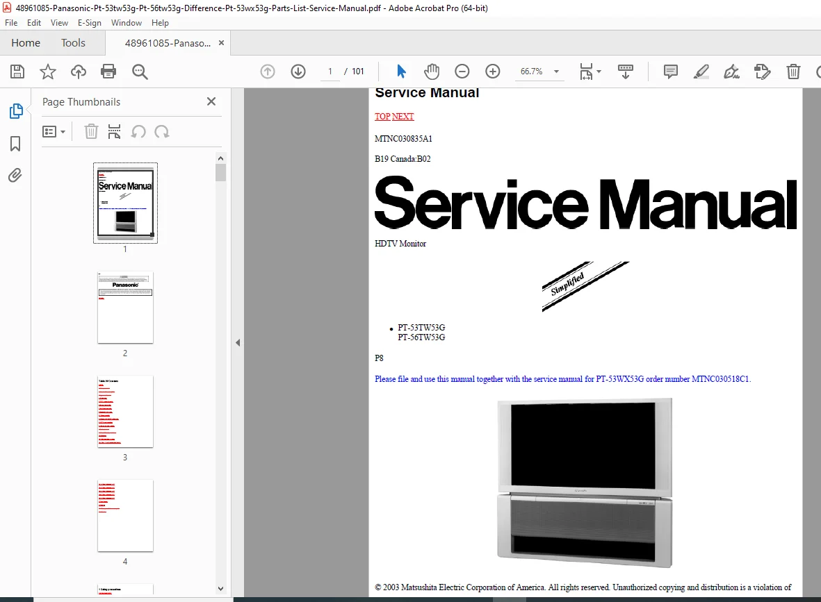
Factory service manual for Panasonic PT-53TW53G (53-inch) and PT-56TW53G (56-inch) HDTV rear projection television monitors. This 101-page technical manual includes schematic diagrams, disassembly procedures, CRT replacement instructions, safety tests, parts lists with locations, and board descriptions. Companion document to PT-53WX53G manual (MTNC030518C1). Essential for TV technicians servicing large-screen projection TVs with lead-free solder repair guidelines and high-voltage safety precautions.
Description
Panasonic PT-53TW53G PT-56TW53G Service Manual HDTV Projection TV Parts List PDF DOWNLOAD
DESCRIPTION
Panasonic PT-53TW53G / PT-56TW53G HDTV Monitor – Service Manual
This comprehensive Panasonic rear projection HDTV service manual provides complete technical documentation for servicing PT-53TW53G (53-inch) and PT-56TW53G (56-inch) HDTV monitors. Essential reference for professional television service technicians and projection TV repair specialists.
📋 FILE DETAILS
- Manual Name: HDTV Monitor Service Manual
- Document Number: MTNC030835A1
- Models Covered:
- PT-53TW53G (53-inch HDTV Projection Monitor)
- PT-56TW53G (56-inch HDTV Projection Monitor)
- Equipment Type: Rear Projection Television (PTV) HDTV Monitor
- Manufacturer: Panasonic (Matsushita Electric Corporation of America)
- Publication Date: 2008 (February 14)
- Region Code: B19 Canada:B02
- Pages: 101 pages
- PDF Quality: High-quality factory original documentation
- File Size: 2.9 MB
- Copyright: 2003 Matsushita Electric Corporation of America
Important Note: This manual should be used together with service manual for PT-53WX53G (order number MTNC030518C1) for complete coverage.
📺 EQUIPMENT OVERVIEW
Panasonic PT-53TW53G / PT-56TW53G Large-screen HDTV rear projection monitors featuring:
- 53-inch and 56-inch projection screens
- HDTV compatibility (1080i support)
- Three-CRT optical projection system (Red, Green, Blue)
- High-voltage CRT technology
- Advanced signal processing
- Multiple A/V inputs (rear and front)
- S-VHS input capability
🔧 MANUAL SECTIONS & CONTENTS
SECTION 1: SAFETY PRECAUTIONS
General Guidelines:
- Isolation transformer requirements for safe servicing
- High voltage safety protocols
- Picture tube handling precautions (implosion hazards)
- X-ray radiation shielding requirements
- Personal protective equipment (safety goggles, heavy gloves)
- Anode discharge procedures
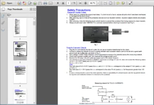
Leakage Current Tests:
- Cold check procedures – Resistance measurements between AC plug and exposed metallic parts (240kΩ to 5.2MΩ specification)
- Hot check procedures – AC potential testing with 1.5kΩ resistor and 0.15F capacitor (0.75V RMS maximum specification)
- Hot check circuit diagrams
- Current measurement limits (0.5mA maximum)
Insulation Test:
- 1080VAC/60Hz application procedures
- Current measurement specifications (0.5mA to 2.0mA)
- Exposed metallic parts testing protocols
X-Ray Radiation Safety:
- High voltage section radiation sources
- Picture tube radiation precautions
- Safe exposure distance guidelines
- Test bench safety requirements
SECTION 2: ABOUT LEAD FREE SOLDER (PbF)
Lead-Free Solder Information:
- Environmental conservation compliance
- PbF solder composition: Sn+Ag+Cu (Tin, Silver, Copper)
- PCB identification markings (“PbF” or leaf symbol)
Soldering Cautions:
- Higher melting point – 50-70°F (30-40°C) higher than standard solder
- Recommended temperature – 700 ± 20°F (370 ± 10°C)
- Splash prevention (avoid exceeding 1100°F/600°C)
- Mixing PbF and Pb solder procedures
- Double-layered board precautions
Suggested PbF Solder Types:
- Sn+Ag+Cu (tin, silver, copper) – primary
- Sn+Cu (tin, copper) – alternative
- Sn+Zn+Bi (tin, zinc, bismuth) – alternative
SECTION 3: IMPORTANT SAFETY TESTS
Measuring High Voltage (H.V.):
- Anode cap access procedures
- FBT (Flyback Transformer) distributor measurement
- Anode lead removal and reinstallation instructions
- Locking cap rotation procedures
- High voltage meter connection points
High Voltage Specifications:
- All black video signal (1080i): 31.5 ± 1.0kV
- NTSC white pattern: 30.1 ± 1.5kV
- HD 1080i white pattern: 30.1 ± 1.5kV
- C514 capacitor adjustment (1800pF, 2000pF, 2400pF, 2700pF options)
(EHT) Protector Operation Check:
- Over-voltage test procedures
- Cabinet-back-removed testing protocols
- 120V AC nominal application
SECTION 4: SERVICE NOTES
- Service-specific technical information
- Repair guidelines and best practices
- Component replacement notes
SECTION 5: PTV LOCATION OF CONTROLS
- Complete control panel layout for PT-53TW53G / PT-56TW53G
- Button and switch identification
- Input selector locations
- Front and rear panel configurations
SECTION 6: RECEIVER FEATURE TABLE
- Comprehensive feature specifications
- Input/output capabilities
- Signal compatibility chart
- Resolution support details
SECTION 7: BOARD DESCRIPTION TABLE
- A-Board functions and specifications
- K-Board description
- G-Board description
- Power supply board details
- Signal processing board identification
- Board interconnection overview
SECTION 8: DISASSEMBLY FOR SERVICE
8.1 Chassis Assembly:
- Complete disassembly procedures
- Screw locations and removal sequences
- Speaker grille removal (grip panel from sides and middle upper)
- Cabinet separation techniques
8.2 Disassembly for CRT Replacement:
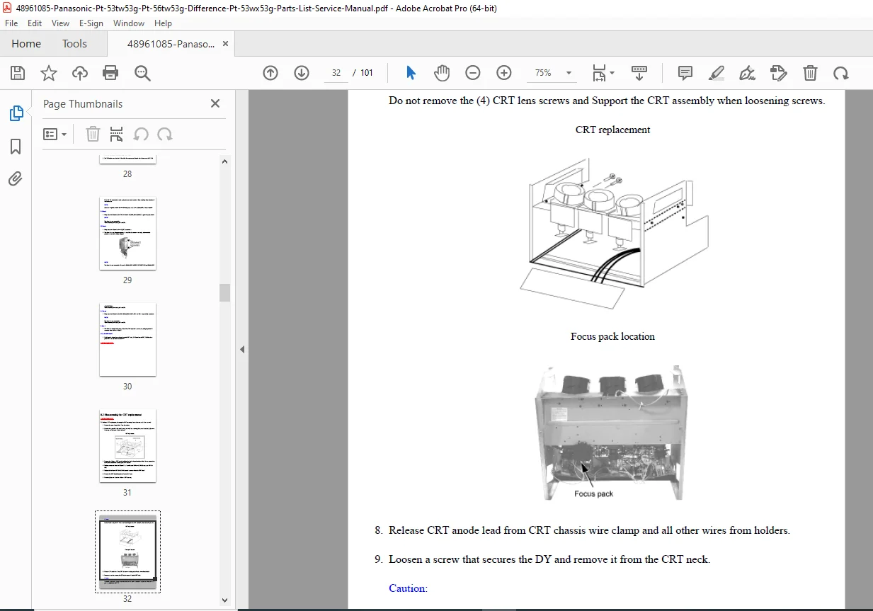
- Picture tube removal procedures
- Optical block dismounting
- High voltage lead disconnection
- CRT handling safety protocols
- Convergence realignment after replacement
8.3 PTV Screen Assemblies:
- Projection screen removal and installation
- Optical block mounting hole adjustments
- Different size screen accommodation
- Optical alignment procedures
- Screen assembly warnings
8.4 Screen Assemblies Warning:
- Critical safety information for screen handling
- Proper support and positioning
- Damage prevention guidelines
SECTION 9: CONDUCTOR VIEWS
9.1 K and G-Board Printed Circuit:
- Component-side conductor views
- Solder-side trace patterns
- Test point locations
- Signal path identification
SECTION 10: SCHEMATICS
10.1 Schematic Diagrams Notes:
- Reading schematic conventions
- Symbol definitions
- Connection notations
10.2 Notas de los Diagramas Esquemáticos:
- Spanish language schematic notes
10.3-10.7 A-Board Schematic (1 of 5 through 5 of 5):
- Complete five-page A-Board schematic set
- Power supply circuits
- Signal processing circuits
- High voltage generation circuits
- Deflection circuits
- Audio circuits
- Input/output circuits
SECTION 11: PARTS LOCATION
- Visual component identification diagrams
- Board layout views showing component positions
- Reference designator locations
- Critical component highlighting
SECTION 12: PARTS LIST
12.1 Description of Abbreviations Guide:
- Part number nomenclature explanation
- Abbreviation definitions
- Component coding system
12.2 Parts List:
- Complete parts catalog with Panasonic part numbers
- Component specifications and values
- Board-specific parts breakdown
- Model-specific differences (PT-53TW53G vs PT-56TW53G)
Sample Parts Included:
- C531, C533, C535: CAP E 47UF/16V (PT-53TW53G specific)
- EEUFC1V561B: CAP E 560UF-35V capacitors
- Terminal rear A/V bracket assemblies
- Optical components
- CRT-specific components
- Power supply components
⚙️ KEY TECHNICAL FEATURES
High Voltage System:
- 50kV capable CRT technology
- Flyback transformer (FBT) with distributor
- EHT (Extra High Tension) protector
- Anode voltage regulation circuitry
- High voltage safety interlock systems
Optical Projection System:
- Three-CRT design (Red, Green, Blue)
- Precision optical block alignment
- Adjustable mounting for different screen sizes
- Convergence adjustment capabilities
- Lens and mirror assemblies
Signal Processing:
- HDTV 1080i support
- NTSC compatibility
- Multiple A/V input processing
- S-VHS input capability
- Advanced video processing circuitry
🎯 IDEAL FOR
- Professional television service technicians
- Projection TV repair specialists
- Consumer electronics repair shops
- Panasonic authorized service centers
- Home theater installation companies
- A/V equipment maintenance technicians
- Technical schools and training programs
- Independent TV repair businesses
⚠️ CRITICAL SAFETY INFORMATION
High Voltage Warnings: This manual contains comprehensive safety protocols for servicing high-voltage projection television systems. Rear projection TVs operate at dangerous voltages (31.5kV) requiring:
- Qualified technician service only
- Proper discharge procedures before service
- Calibrated high voltage measurement equipment
- X-ray radiation awareness and protection
- Proper grounding and isolation techniques
CRT Handling:
- Implosion hazard from atmospheric pressure (14.7 lbs/sq.in)
- Requires safety goggles and heavy gloves
- Careful handling to prevent glass damage
- Proper disposal procedures
💡 WHY THIS MANUAL IS ESSENTIAL
Large-Screen Projection TV Complexity: Rear projection HDTVs are sophisticated systems requiring specialized knowledge: ✓ Three separate CRT tubes requiring precision alignment ✓ High voltage systems (31.5kV) demanding exact specifications ✓ Optical projection systems with critical focus and convergence ✓ Lead-free solder repair requiring modified techniques ✓ Multiple interconnected circuit boards ✓ Complex signal processing for HDTV formats
Companion to PT-53WX53G Manual: This manual documents the differences and specific procedures for PT-53TW53G/PT-56TW53G models. When used with PT-53WX53G service manual (MTNC030518C1), provides complete service coverage.
Complete Parts Reference: Unlike generic service guides, this factory manual includes exact Panasonic part numbers, locations, and specifications for every replaceable component.
🔍 TROUBLESHOOTING & REPAIR
Covered Service Procedures:
- High voltage measurement and adjustment
- CRT replacement and convergence alignment
- Optical block service and realignment
- Circuit board repair with lead-free solder
- Power supply troubleshooting
- Signal processing circuit diagnosis
- Input/output circuit repair
Test Equipment Requirements:
- Calibrated high voltage meter
- Insulation tester capable of 1080VAC
- DVM with 1000 ohms/volt sensitivity minimum
- Leakage current tester (Simpson 229, Sencore PR57 or equivalent)
- Temperature-controlled soldering station (700°F for PbF)
🚀 Download instantly and service with confidence! Stop struggling with large-screen projection TV repairs without proper documentation. This factory-authorized service manual provides the exact specifications, procedures, and safety protocols needed to service Panasonic PT-53TW53G and PT-56TW53G HDTV monitors safely and effectively. Essential for anyone servicing these complex rear-projection television systems.
Pricing rationale:
- 101 pages of technical content
- Covers two large-screen projection TV models (53″ and 56″)
- Factory-authorized Panasonic documentation
- Includes complete schematic diagrams and parts lists
- Lead-free solder repair guidelines (specialized knowledge)
- High-voltage safety procedures (critical for technician safety)
- Companion manual to PT-53WX53G (requires both for complete coverage)
- Older projection TV technology (2008 publication, declining installed base)
- Rear projection TVs largely obsolete but still serviced
- Specialized technician audience
- Complete CRT replacement and optical alignment procedures