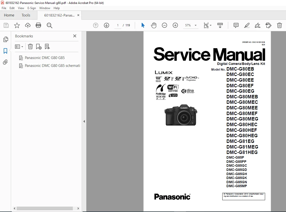
Panasonic Lumix DMC-G80 G81 G85 Service Manual Repair Guide PDF
Original price was: $95.00.$18.95Current price is: $18.95.
Official Panasonic service manual for Lumix DMC-G80/G81/G85 mirrorless digital cameras and bundled lens kits. Complete repair guide with disassembly procedures, schematic diagrams, troubleshooting, adjustments, exploded views, and parts lists. Essential technical documentation for camera technicians servicing micro four thirds systems.
Description
Panasonic Lumix DMC-G80 G81 G85 Service Manual Repair Guide PDF DOWNLOAD
DESCRIPTION:
Complete Factory Service & Repair Manual for Panasonic Lumix G80/G81/G85 Series
This official Panasonic Lumix G80 service manual PDF provides comprehensive technical documentation for repairing and servicing the complete DMC-G80/G81/G85 mirrorless camera series and bundled interchangeable lens kits. Essential professional resource for camera technicians, repair shops, and electronics service professionals working with Panasonic micro four thirds digital imaging systems.
Models Covered – Complete Camera & Lens Kit Variations
Body-Only Models:
- DMC-G80EB, DMC-G80EC, DMC-G80EE, DMC-G80EF, DMC-G80EG
- DMC-G81EG
- DMC-G85P, DMC-G85PP, DMC-G85GC, DMC-G85GD, DMC-G85GH, DMC-G85GK, DMC-G85GN
Kit with H-FS12060 Lens (12-60mm):
- DMC-G80MEB, DMC-G80MEC, DMC-G80MEE, DMC-G80MEF, DMC-G80MEG
- DMC-G81MEG
- DMC-G85MP, DMC-G85MPP, DMC-G85MGN
Kit with H-FS14140 Lens (14-140mm):
- DMC-G80HEC, DMC-G80HEF, DMC-G80HEG
- DMC-G81HEG
- DMC-G85HGH
Kit with H-FS1442A Lens (14-42mm):
- DMC-G85KGC, DMC-G85KGN
Color Variations:
- (K) Black Type – All models
Comprehensive Service Manual Contents
1. SAFETY PRECAUTIONS & WARNINGS
General Guidelines:
- Critical component identification and replacement procedures
- Isolation transformer requirements
- Lead dress and protective device installation
- Post-service safety verification
Leakage Current Testing:
- Cold check procedures (1MΩ – 5.2MΩ resistance verification)
- Hot check procedures (0.75V RMS maximum voltage limits)
- Equipment safety validation protocols
High Voltage Safety:
- E.Capacitor discharge procedures on Flash P.C.B.
- Insulation and safety protocols
- Voltmeter verification requirements
ESD Protection:
- Electrostatic discharge prevention for sensitive components
- Proper grounding techniques
- Antistatic handling procedures
- Wrist strap requirements
Battery Safety:
- Lithium-ion battery replacement procedures
- Lithium battery disposal and recycling (U.S. regulations)
- Critical component handling guidelines
- Battery pack replacement for all G80/G81/G85 series
2. SERVICE NAVIGATION
- Introduction to service procedures
- Bundled lens service cross-references:
- H-FS12060E/GK/PP (Order No. DSC1604008CE)
- H-FS14140PP/E/GK (Order No. DSC1305023CE/DSC1506509SE)
- H-FS1442APP/E/GK (Order No. DSC1302014CE/DSC1506508SE)
- Important service notices and technical bulletins
- Detailed service notes
- Lead-free solder (PbF) handling guidelines
- Model suffix identification (NTSC vs PAL systems)
3. COMPLETE TECHNICAL SPECIFICATIONS
Camera Body Specifications:
- Sensor System: Digital Live MOS sensor (Micro Four Thirds)
- Lens Mount: Micro Four Thirds interchangeable lens mount
- Image Stabilization: 5-axis Dual I.S. body stabilization
- Video Recording: 4K video capability
- LCD Display: Vari-angle touch screen
- Electronic Viewfinder: OLED Live View Finder
- Connectivity: Wi-Fi integrated (Jack P.C.B. circuit)
- Flash System: Built-in flash with hot shoe
- Power Supply: Lithium-ion battery pack
- Gyro System: Multi-axis gyroscopic stabilization
Bundled Lens Specifications:
- H-FS12060: 12-60mm f/3.5-5.6 ASPH Power O.I.S.
- H-FS14140: 14-140mm f/3.5-5.6 ASPH Mega O.I.S.
- H-FS1442A: 14-42mm f/3.5-5.6 ASPH Mega O.I.S.
4. LOCATION OF CONTROLS & COMPONENTS
Camera Body Layout:
- External control identification
- Internal component locations
- PCB mounting positions
- Sensor and mechanical assembly locations
Lens Unit Components:
- Optical element assembly
- Focus and zoom mechanisms
- Image stabilization units
- Electronic contact configuration
5. SERVICE MODE & DIAGNOSTICS
Error Code Memory Function:
- Accessing service mode
- Error code retrieval procedures
- Diagnostic code interpretation
- System status verification
6. TROUBLESHOOTING GUIDE
Body and Interchangeable Lens Checking Methods:
- Systematic troubleshooting procedures for camera body
- Lens communication diagnostics
- Mechanical function verification
- Electronic system fault isolation
Wi-Fi Circuit Diagnostics (Jack P.C.B.):
- Wireless connectivity troubleshooting
- RF circuit testing
- Network configuration verification
7. SERVICE FIXTURES & TOOLS
Required Service Equipment:
- Specialized service fixtures and tools list
- Clean box requirements for sensor service
- Flange back adjustment positioning
- PCB checking service positions
Main P.C.B. Replacement:
- Critical procedures and precautions
- Configuration and calibration requirements
- System initialization protocols
8. DISASSEMBLY & ASSEMBLY INSTRUCTIONS
Camera Body Disassembly:
- Step-by-step component removal procedures
- Proper sequence for major assemblies
- Fastener identification and torque specifications
- Cable routing and connector locations
- PCB removal and installation
- Sensor assembly service procedures
- Mechanical housing disassembly
Lens Unit Disassembly:
- Optical assembly service procedures
- Focus and zoom mechanism disassembly
- Image stabilization unit access
- Electronic component replacement
9. MEASUREMENTS & ADJUSTMENTS
Matrix Chart for Replaced Parts:
- Required adjustments after component replacement
- Calibration procedures cross-reference
- Critical alignment requirements
Adjustment Procedures:
- Flange back distance calibration
- Image sensor alignment
- Autofocus system calibration
- Image stabilization calibration
- Electronic viewfinder adjustment
- LCD display calibration
10. MAINTENANCE PROCEDURES
External Cleaning:
- Proper cleaning techniques
- Approved cleaning materials
- Sensor cleaning protocols
- Lens element maintenance
11. COMPREHENSIVE TECHNICAL DIAGRAMS
Block Diagrams:
- Overall system block diagram
- System control architecture
- Video/Audio process (3 detailed diagrams)
- Gyro system block diagram
- Flash/Hot shoe circuitry
- Lens interface block diagram
- Power supply systems (3 detailed diagrams)
Wiring Connection Diagrams:
- Complete interconnection diagrams
- Cable harness routing
- Connector pinout configurations
Schematic Diagrams:
- Complete electronic schematic diagrams
- Component-level circuit analysis
- Signal flow documentation
Printed Circuit Board Layouts:
- PCB component placement diagrams
- Solder-side and component-side views
- Test point locations
- Critical component identification
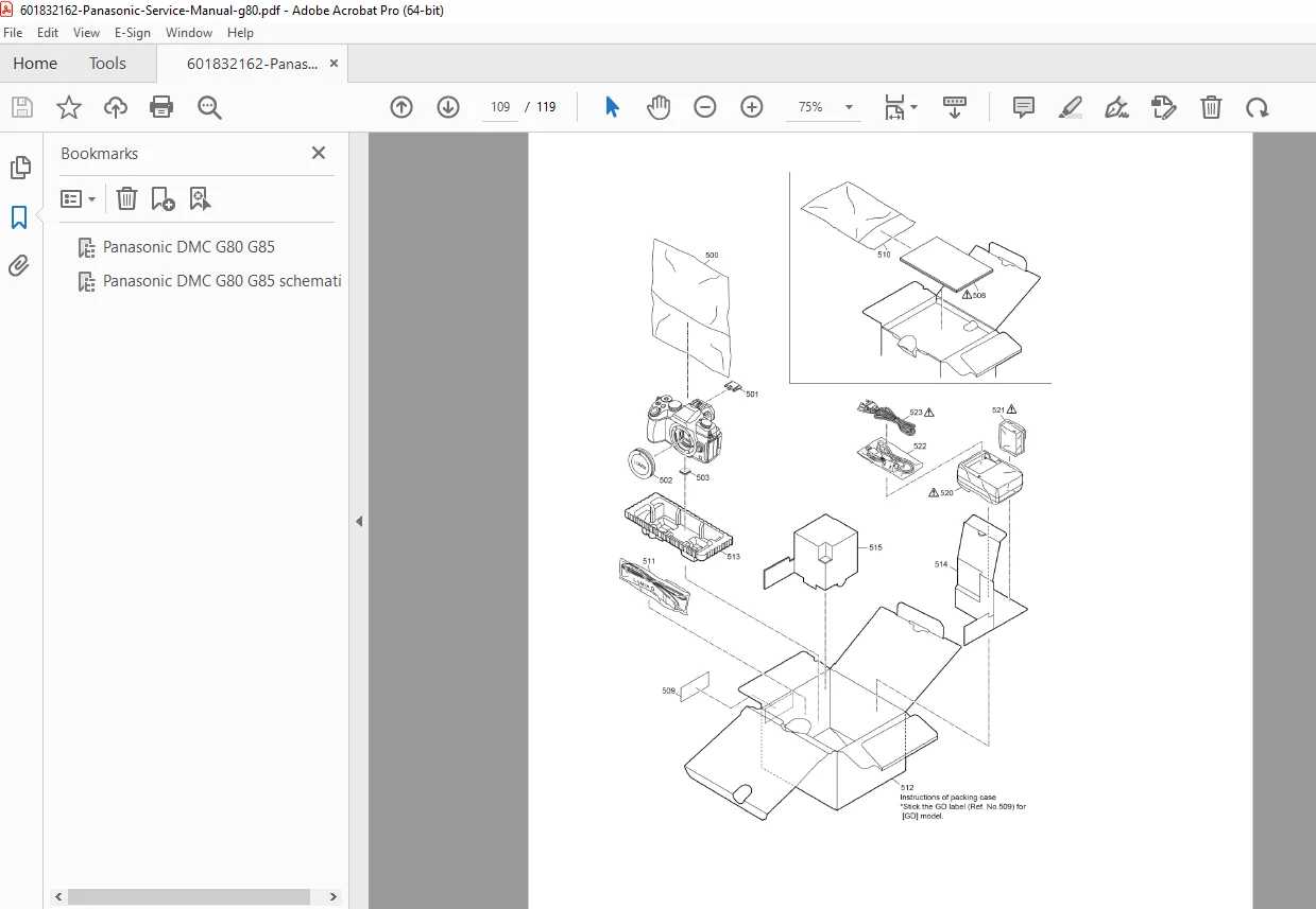
Exploded View Diagrams:
- Mechanical assembly exploded views
- Part number identification
- Assembly sequence illustration
- Hardware and fastener details
12. REPLACEMENT PARTS LIST
Comprehensive Parts Catalog:
- Complete parts identification numbers
- Component descriptions
- Assembly reference numbers
- Cross-reference to exploded views
- Critical component markings
- Availability and ordering information
Key Features of This Service Manual
✓ 119 pages of professional technical documentation
✓ High-resolution diagrams – Clear schematics, PCB layouts, exploded views
✓ Multiple model coverage – G80, G81, G85 and all regional variants
✓ Lens kit documentation – Three bundled lens configurations covered
✓ Complete troubleshooting – Systematic diagnostic procedures
✓ Safety compliance – ESD protection, high voltage safety protocols
✓ Professional quality – Official Panasonic factory service manual
✓ Lead-free solder – Modern manufacturing standards documented
✓ Adjustment procedures – Critical calibration and alignment guides
Who Should Use This Manual
This DMC-G85 repair guide is essential for:
- Professional camera repair technicians
- Authorized Panasonic service centers
- Independent camera repair shops
- Electronics service professionals
- Imaging equipment maintenance specialists
- Technical training facilities
- Photography equipment rental houses
- Advanced hobbyist camera technicians
Technical Service Capabilities Enabled
Mechanical Repairs:
- Housing and chassis repair
- Shutter mechanism service
- Lens mount replacement
- Button and control replacement
- LCD screen replacement
- Electronic viewfinder service
Electronic Repairs:
- PCB-level component replacement
- Flash circuit repair
- Wi-Fi module troubleshooting
- Power supply diagnostics
- Image sensor service
- Gyro system calibration
Optical Adjustments:
- Flange back calibration
- Focus accuracy adjustment
- Image stabilization alignment
- Sensor positioning
File Details
| Specification | Details |
|---|---|
| Manual Name | Panasonic Lumix DMC-G80/G81/G85 Service Manual |
| Order Number | DSC1610015CE, B26 |
| Models Covered | DMC-G80/G81/G85 series (All variants – Body, M-Kit, H-Kit, K-Kit) |
| Lens Coverage | H-FS12060, H-FS14140, H-FS1442A (with cross-reference manuals) |
| Publication Date | 2016 |
| Manufacturer | Panasonic Corporation |
| Manual Type | Official Factory Service Manual |
| Total Pages | 119 pages |
| File Format | PDF (Optimized, Searchable) |
| PDF Quality | Excellent – Original factory documentation with clear diagrams and high-resolution schematics |
| Language | English |
| File Size | 16.1 MB |
| Document Security | Not encrypted – Full access to all content |
Copyright & Legal Notice
© Panasonic Corporation 2016. This is an official service manual. Unauthorized copying and distribution is a violation of law. This manual is provided for legitimate service and repair purposes only.
Why This Manual is Essential
Reduces Service Time:
Comprehensive schematic diagrams and troubleshooting guides enable rapid fault diagnosis and repair, minimizing equipment downtime.
Ensures Quality Repairs:
Factory-authorized procedures guarantee repairs meet Panasonic’s original manufacturing standards and specifications.
Prevents Costly Mistakes:
Detailed safety precautions, ESD protection guidelines, and critical component identification prevent damage during service.
Supports Professional Service:
Complete technical specifications enable proper calibration, adjustment, and verification of all camera systems.