Panasonic Sc hte180 Service Manual And Repair Guide – PDF DOWNLOAD
Original price was: $35.95.$22.95Current price is: $22.95.
Panasonic Sc hte180 Service Manual And Repair Guide
Description
Panasonic Sc hte180 Service Manual And Repair Guide
FILE DETAILS:
LANGUAGE:ENGLISH
PAGES:91
DOWNLOADABLE:YES
FILE TYPE:PDF
PANASONIC SC HTE180 SERVICE MANUAL AND REPAIR GUIDE – PDF DOWNLOAD:
IMAGES PREVIEW OF THE MANUAL:
DESCRIPTION:
Panasonic Sc hte180 Service Manual And Repair Guide
1 Safety Precautions
1.1. General Guidelines
1. IMPORTANT SAFETY NOTICE
There are special components used in this equipment which are important for safety. These parts are marked by in the Schematic Diagrams, Circuit Board Layout, Exploded Views and Replacement Parts List. It is essential that these critical parts should be replaced with manufacturer’s specified parts to prevent X-RADIATION, shock, fire, or other hazards. Do not modify
the original design without permission of manufacturer.
2. An Isolation Transformer should always be used during the servicing of AC Adaptor whose chassis is not isolated from the AC power line. Use a transformer of adequate power rating as this protects the technician from accidents resulting in personal injury from electrical shocks. It will also protect AC Adaptor from being damaged by accidental shorting that may occur during
servicing.
3. When servicing, observe the original lead dress. If a short circuit is found, replace all parts which have been overheated or damaged by the short circuit.
4. After servicing, see to it that all the protective devices such as insulation barriers, insulation papers shields are properly installed.
5. After servicing, make the following leakage current checks to prevent the customer from being exposed to shock hazards.
1.1.1. Leakage Current Cold Check
1. Unplug the AC cord and connect a jumper between the two prongs on the plug.
2. measure the resistance value, with an ohmmeter between the jumpered AC plug and each exposed metallic cabinet part on
the equipment such as screwheads, connectors, control shafts, etc. When the exposed metallic part has a return path to the chassis, the reading should be between 1MΩ and 5.2MΩ. When the exposed metal does not have a return path to the chassis, the reading must be
1.1.2. Leakage Current Hot Check
1. Plug the AC cord directly into the AC outlet. Do not use an isolation transformer for this check.
2. Connect a 1.5kΩ, 10 watts resistor, in parallel with a 0.15μF capacitors, between each exposed metallic part on the set and a good earth ground such as a water pipe, as shown in Figure 1-1.
3. Use an AC voltmeter, with 1000 ohms/volt or more sensitivity, to measure the potential across the resistor.
4. Check each exposed metallic part, and measure the voltage at each point.
5. Reverse the AC plug in the AC outlet and repeat each of the above measurements.
6. The potential at any point should not exceed 0.75 volts RMS. A leakage current tester (Simpson Model 229 or equivalent) may be used to make the hot checks, leakage current must not exceed 1/2 milliamp. In case a measurement is outside of the limits specified, there is a possibility of a shock hazard, and the equipment should be repaired and rechecked before it is
returned to the customer
TABLE OF CONTENTS:
Panasonic Sc hte180 Service Manual And Repair Guide
1 Safety Precautions 3
1.1. General Guidelines 3
1.2. Caution for AC Cord (For EB only) 4
1.3. Before Repair and Adjustment 5
1.4. Protection Circuitry 5
1.5. Caution For Fuse Replacement 5
1.6. Safety Part Information 6
2 Warning 7
2.1. Prevention of Electrostatic Discharge (ESD)
to Electrostatically Sensitive (ES) Devices 7
2.2. Service caution based on Legal restrictions 8
3 Service Navigation 9
3.1. Service Information 9
3.2. Error Code Troubleshooting 9
4 Specifications 10
5 General/Introduction 11
5.1. Basic Control & OneTouch Connection (NFC) 11
6 Location of Controls and Components 12
6.1. Main Unit & Remote Control Key Button
Operations12
7 Service Mode 13
7.1. Self Diagnostic Mode 13
7.2. Self Diagnostic Function Error Code 15
7.3. Doctor Mode 16
8 Disassembly and Assembly Instructions 20
8.1. Disassembly flow chart 21
8.2. Type of screws 21
8.3. Main Parts Location Diagram 22
8.4. Disassembly of Bottom Chassis Block 23
8.5. Disassembly of Main P.C.B. 24
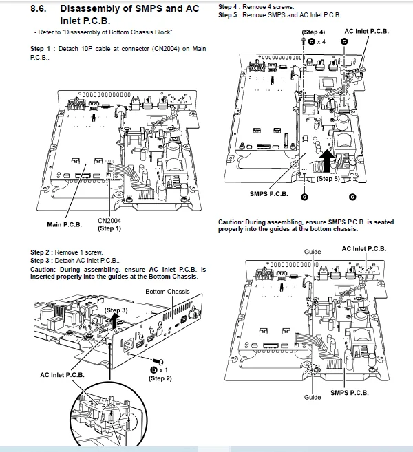
8.6. Disassembly of SMPS and AC Inlet P.C.B. 25
8.7. Disassembly of HDMI P.C.B. 26
8.8. Disassembly of Top Cabinet Ass’y 27
8.9. Disassembly of Panel P.C.B. 28
8.10. Disassembly of Bluetooth Module P.C.B. 29
8.11. Disassembly of NFC P.C.B. 30
8.12. Disassembly of Subwoofer Speaker Unit
(8cm) 31
8.13. Disassembly of Full Range Speaker Unit
(9cm) 32
2
9 Service Position 34
9.1. Checking of Main P.C.B. (Side B) & HDMI
P.C.B. (Side B) 34
9.2. Checking of Main P.C.B. (Side A) & HDMI
P.C.B. (Side A) 35
9.3. Checking of SMPS P.C.B. 36
9.4. Checking of Panel P.C.B. 37
10 Block Diagram 39
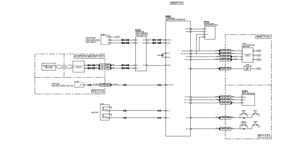
10.1. SYSTEM CONTROL & AUDIO (1/2) BLOCK
DIAGRAM 39
10.2. SYSTEM CONTROL & AUDIO (2/2) BLOCK
DIAGRAM 40
10.3. HDMI BLOCK DIAGRAM 41
10.4. POWER SUPPLY (1/2) BLOCK DIAGRAM 42
10.5. POWER SUPPLY (2/2) BLOCK DIAGRAM 43
11 Wiring Connection Diagram 44
12 Schematic Diagram 45
12.1. Schematic Diagram Notes 45
12.2. HDMI CIRCUIT (1/2) 47
12.3. HDMI CIRCUIT (2/2) 48
12.4. MAIN (MICON) CIRCUIT (1/5) 49
12.5. MAIN (MICON) CIRCUIT (2/5) 50
12.6. MAIN (MICON) CIRCUIT (3/5) 51
12.7. MAIN (MICON) CIRCUIT (4/5) 52
12.8. MAIN (MICON) CIRCUIT (5/5) 53
12.9. MAIN (DAMP) CIRCUIT (1/3) 54
12.10. MAIN (DAMP) CIRCUIT (2/3) 55
12.11. MAIN (DAMP) CIRCUIT (3/3) 56
12.12. AC INLET CIRCUIT 57
12.13. PANEL CIRCUIT 58
12.14. SMPS CIRCUIT 59
13 Printed Circuit Board 60
13.1. HDMI P.C.B. 60
13.2. MAIN P.C.B. (Side A) 61
13.3. MAIN P.C.B. (Side B) 62
13.4. PANEL P.C.B. 63
13.5. SMPS & AC INLET P.C.B. 64
14 Voltage and Waveform Measurement 65
14.1. Voltage Measurement 65
14.2. Waveform Chart 71
15 Exploded View and Replacement Parts List 73
15.1. Cabinet Parts Location 1 73
15.2. Cabinet Parts Location 2 74
15.3. Packaging 75
15.4. Mechanical Replacement Parts List 77
15.5. Electrical Replacement Parts List 79
PLEASE NOTE:
- This is the SAME exact manual used by your dealers to fix your vehicle.
- The same can be yours in the next 2-3 mins as you will be directed to the download page immediately after paying for the manual.
- Any queries / doubts regarding your purchase, please feel free to contact [email protected]