★ TRUSTED BY 321,897+ PROFESSIONALS WORLDWIDE
🏢
Trusted Business
Verified & Licensed
🛡️
Virus Free Files
100% Safe Downloads
🔒
Secure Payment
SSL Protected
Instant Delivery
Available Immediately
Sale!

Piper PA-31-350 Chieftain Illustrated Parts Catalog Manual 2017 PDF

Original price was: $34.95.Current price is: $22.95.

Genuine Piper Aircraft Illustrated Parts Catalog for the PA-31-350 Chieftain. This 871-page manual provides detailed parts lists and exploded-view diagrams for every system on the aircraft, from the airframe and powerplant to avionics and interior furnishings. Essential for owners, mechanics, and restorers needing to identify and order the correct part numbers.

Instant PDF Download
Available immediately
💾
Save to Your Device
Download & keep forever
🛡️
Antivirus Scanned
100% virus-free
🌍
Trusted Worldwide
175,000+ customers

Description

Comprehensive Parts Identification for the Piper PA-31-350 Chieftain

This official Piper Aircraft Parts Catalog is a direct digital reproduction of the document used by Piper service centers to order and track every component of the PA-31-350 Chieftain. This is the master guide for identifying parts, understanding their assembly, and ensuring you are ordering the correct component for your specific aircraft serial number.

Covering production from 1973 through the 1984 model year, this catalog is an indispensable tool for maintenance planning, restoration projects, and parts procurement. Every major assembly of the aircraft is broken down into clear, detailed illustrations with corresponding part numbers, names, and usage notes. It covers a vast range of model years and serial numbers, providing the cross-referencing needed to source parts for older and newer Cheiftains.

File Details

  • Manual Type: Aircraft Illustrated Parts Catalog (IPC)
  • Aircraft Model: Piper PA-31-350 Chieftain
  • Language: English
  • Page Count: 871 Pages
  • File Format: PDF
  • Document Number: 761-487
  • Revision Date: February 27, 2017
  • Publisher: Piper Aircraft, Inc.

What’s Covered in This Parts Catalog

The manual is organized into 14 major sections covering the complete aircraft. The listing of sections and major systems included in this document is as follows:

Complete PDF Bookmark Tree

Complete Bookmarks

The complete bookmarks in the “Piper PA-31-350 Chieftain Illustrated Parts Catalog Manual 2017 PDF” are as follows:

AIRPLANE PARTS CATALOG (761-487)p. 1
REVISIONS STATUSp. 3
INTRODUCTIONp. 4
TABLE OF CONTENTSp. 10
Figure 1. View of Complete Airplanep. 15
SECTION I – WING GROUPp. 16
Figure 2. Wing Installationp. 16
Figure 3. Wing Panel Inboard Parts Installationp. 22
Figure 4. Wing Panel Outboard Parts Installationp. 26
Figure 5. Wing Panel Leading Edge Assemblyp. 30
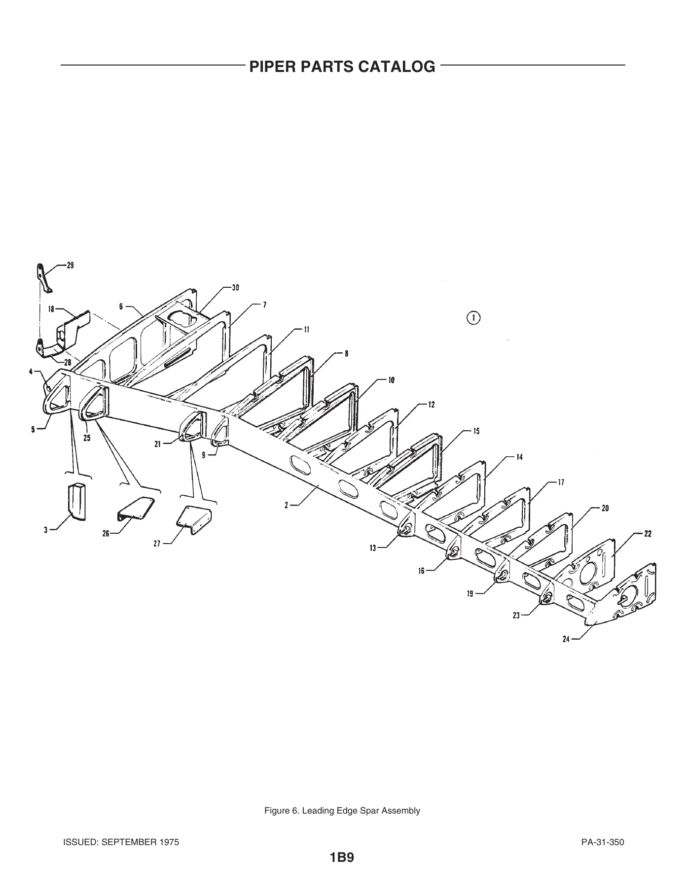
Figure 6. Leading Edge Spar Assemblyp. 34
Figure 7. Wing Panel Rear Spar Assemblyp. 38
Figure 8. Aileron Assemblyp. 46
Figure 9. Flap Assemblyp. 50
SECTION II – FUSELAGE GROUPp. 55
Figure 10. Fuselage Assemblyp. 55
Figure 11. Fuselage Upper Forward Sectionp. 58
Figure 12. Fuselage Upper Cabin Section Assemblyp. 62
Figure 13. Pilot Door Fuselage Frame Installationp. 66
Figure 14. Fuselage Lower Forward Section Assemblyp. 69
Figure 15. Fuselage Lower Forward Frame Assemblyp. 74
Figure 16. Lower Rear Section Assemblyp. 80
Figure 17. Fuselage Lower Center Frame Assemblyp. 85
Figure 18. Fuselage Lower Rear Frame Assemblyp. 88
Figure 19. Cargo Door Fuselage Frame Installationp. 91
Figure 20. Fuselage Aft Sectionp. 96
Figure 21. Floorboard Installationp. 102
Figure 22. Structure Installation, Sta. 57 to Sta. 215p. 105
Figure 23. Structure Installation, Sta. 215 to Sta. 244p. 108
Figure 24. Windshield Installationp. 112
Figure 25. Window Installation (Serial Nos. 31-5001 to 31-7652177 incl.)p. 116
Figure 25A. Window Installation (Serial Nos. 31-7752001 and up)p. 120
Figure 26. Emergency Exit Window Installationp. 124
Figure 27. Cabin Entrance Door Installationp. 129
Figure 28. Upper Cabin Entrance Doorp. 133
Figure 29. Lower Cabin Entrance Doorp. 136
Figure 30. Forward Baggage Door Installationp. 142
Figure 31. Cargo Door Assembly and Installationp. 146
Figure 32. Pilot Door Installationp. 150
Figure 33. Pilot Door Assembly (Complete)p. 153
SECTION III – TAIL SURFACE GROUPp. 158
Figure 34. Tail Surfaces Installationp. 158
Figure 35. Fin Assemblyp. 162
Figure 36. Rudder Assemblyp. 166
Figure 37. Stabilizer Assemblyp. 170
Figure 38. Elevator Assemblyp. 174
SECTION IV – LANDING GEAR GROUPp. 179
Figure 39. Main Landing Gear Installationp. 179
Figure 40. Main Gear Strut Assemblyp. 185
Figure 41. Main Wheel Assembly (Cleveland)p. 190
Figure 41A. Main Wheel Assembly (Goodyear)p. 193
Figure 42. Main Wheel Brake Assembly (Cleveland) (Serial Nos. 31-5001 to 31-7652075 incl.)p. 196
Figure 42A. Main Wheel Brake Assembly (Cleveland) (Serial Nos. 31-7652076 and up)p. 199
Figure 42B. Main Wheel Brake Assembly (Cleveland) (Serial Nos. 31-7852121, 31-8052031 and up)p. 202
Figure 42C. Main Wheel Brake Assembly (Goodyear)p. 205
Figure 43. Nose Landing Gear Installationp. 208
Figure 44. Nose Gear Strut Assemblyp. 214
Figure 45. Nose Wheel Assemblyp. 219
Figure 46. Nose Gear Steering Mechanism Installationp. 222
Figure 47. Brake System Installationp. 225
Figure 48. Dual Brake Installationp. 229
Figure 49. Master Cylinder and Parking Brake Valvep. 232
SECTION V – CABIN EQUIPMENT GROUPp. 236
Figure 50. Furnishings Installation – Cargo Versionp. 236
Figure 51. Furnishings Installation – Commuter Version (Serial Numbers 31-5001 to 31-7652177 incl.)p. 240
Figure 51A. Furnishings Installation-Commuter Version (Serial Number 31-7752001 and up)p. 243
Figure 52. Furnishings Installation – Corporate Version (Serial Numbers 31-5001 to 31-7652177 incl.)p. 249
Figure 53. Furnishings Installation – Executive Version (Serial Numbers 31-5001 to 31-7652177 incl.)p. 252
Figure 53A. Furnishing Installation – Executive Version (Serial Numbers 31-7752001 and up)p. 256
Figure 54. Cabin Interior Finishing Installation (Serial Numbers 31-5001 to 31-7652177 incl.)p. 264
Figure 54A. Cabin Interior Finishing Installation (Serial Numbers 31-7752001 to 31-7852029 inclusive)p. 269
Figure 54B. Cabin Interior Finishing Installation (Serial Numbers 31-7852030 and up)p. 273
Figure 55. Cabin Headliner Installationp. 279
Figure 56. Carpet Installationp. 282
Figure 57. Baggage Compartments Finishing Installationp. 286
Figure 58. Seat Installation – Frontp. 290
Figure 59. Seats Installation – Third and Fourth Forward Facingp. 297
Figure 59A. Seat Installation – Third and Fourth Forward Facing (Serial Numbers 31-8152001 and up)p. 303
Figure 60. Seats Installation – Third and Fourth Aft Facingp. 307
Figure 60A. Seats Installation – Third and Fourth Aft Facing(Serial Numbers 31-8152001 and up)p. 312
Figure 61. Seats Installation – Passengerp. 316
Figure 62. Seat Installation – Ninthp. 324
Figure 63. Seat Installation – Tenthp. 329
Figure 63A Seats Installation – Tenth (Serial Numbers 31-8152001 and up)p. 333
Figure 64. Cabin Divider Panels Installation (Serial No’s. 31-5001 to 31-7652177 incl.)p. 337
Figure 64A. Cabin Privacy Curtain Installationp. 340
Figure 65. Refreshment Cabinet and Beverage Dispenser Installation (Serial Numbers 31-5001 to 31-7652177 incl.)p. 343
Figure 66. Refreshment Cabinet and Beverage Dispenser Installation (Serial Numbers 31-5001 to 31-7652177 incl.)p. 347
Figure 67. Toilet Installation – Side Facingp. 350
Figure 68. Toilet Installation – 9th Seat Positionp. 354
Figure 68A. Toilet Installation – 9th Seat Position(Serial Numbers 31-7752096 and up)p. 358
Figure 69. Toilet Installatin – 10th Seat Position (Serial Numbers 31-5001 to 31-7652177 incl.)p. 362
SECTION VI – INSTRUMENT GROUPp. 365
Figure 70. Instrument Panel Installationp. 365
Figure 71. Dual Instrument Panel Installationp. 371
Figure 72. Miscellaneous Air and Fluid Lines Installationp. 375
Figure 73. Dual Instrument Air System Installationp. 379
Figure 74. Instrument Pressure System Installation (Serial Numbers 31-5001 to 31-7652123 incl.)p. 382
Figure 74A. Instrument Pressure System Installation (Serial Numbers 31-7652124 and up)p. 386
Figure 75. Static Pressure System Installationp. 390
Figure 76. Tachometer Shaft Installationp. 394
SECTION VII – POWER PLANT GROUPp. 397
Figure 77. Power Plant Installationp. 397
Figure 78. Engine Baffle Installationp. 402
Figure 79. Oil Cooler and Breather System Installationp. 405
Figure 80. Three Blade Propeller Assemblyp. 409
Figure 81. Propeller Synchrophaser System Installation (Serial Numbers 31-5001 to 31-7852037 incl.)p. 413
Figure 81A. Propeller Synchrophaser System Installation (Serial Number 31-7852038 and up)p. 417
Figure 82. Engine Controls Installationp. 420
Figure 83. Engine Cowl lnstallationp. 424
Figure 84. Cowl Flap Actuating Mechanism Installationp. 427
Figure 85. Nacelle Installationp. 431
Figure 86. Nacelle Locker Door Assembly and Installationp. 436
SECTION VIII – FUEL SYSTEM GROUPp. 441
Figure 87. Left Engine Fuel System Installationp. 441
Figure 88. Right Engine Fuel System Installationp. 446
Figure 89. Fuel Flow and Prassure Gause Installationp. 451
Figure 90. Fuel System Componentsp. 455
Figure 91. Fuel Controls Installationp. 458
Figure 92. Main Fuel Cell and Liner Installationp. 463
Figure 93. Auxiliary Fuel Cell and Liner Installationp. 467
Figure 93A. Nacelle Fuel System Installation (Nayak) (Serial Numbers 31-8152001 and up)p. 471
SECTION IX – CONTROL SYSTEMS GROUPp. 476
Figure 94. Pedestal Installationp. 476
Figure 95. Pedestal Control Assemblyp. 481
Figure 96. Aileron Control Installationp. 485
Figure 97. Aileron Trim Installationp. 489
Figure 98. Rudder Control Installationp. 494
Figure 99, Rudder Trim Installationp. 498
Figure 100. Elevator Control Installationp. 502
Figure 101. Elevator Trim Installationp. 506
Figure 102. Flap Control Installationp. 510
Figure 103. Control Wheel Installationp. 515
Figure 104. Rudder Pedal Installationp. 520
SECTION X – HYDRAULIC SYSTEM GROUPp. 524
Figure 105. Forward Hydraulic System Installationp. 524
Figure 106. Aft Hydraulic System Installationp. 528
Figure 107. Hydraulic Pumps Installationp. 531
Figure 108. Hydraulic System Components (Ozone)p. 535
Figure 108A. Hydraulic System Components (Wiebel)p. 539
Figure 109. Hydraulic Powerpak Assembly (Ozone)p. 543
Figure 109A. Hydraulic Powerpak Components (Ozone)p. 547
Figure 110. Hydraulic Powerpak Assembly (Wiebel)p. 550
Figure 110A. Hydraulic Powerpak Components (Wiebel)p. 554
Figure 111. Landing Gear Selector Mechanism Installationp. 557
SECTION XI – ENVIRONMENTAL GROUPp. 561
Figure 112. Heater and Defroster System Installation (See Code “A”)p. 561
Figure 112A. Heater and Defroster System Installation (See Code “A”)p. 565
Figure 113. Heater Installation (See Code “A” On Next Page For Effectivity)p. 569
Figure 113A. Heater Installation. (See Code “A” on Next Page for Effectivity)p. 572
Figure 114. Heater Assemblyp. 575
Figure 115. Heater Componentsp. 579
Figure 116. Ventilation System Installationp. 583
Figure 116A. Air Distribution Duct Installation (Serial Numbers 31-7852030 and up)p. 587
Figure 117. Cabin Exhaust Vent and Blower Installationp. 590
Figure 118. Air Conditioning Evaporator Installationp. 593
Figure 119. Air Conditioning Freon System Installationp. 596
Figure 120. Air Conditioning Condenser and Scoop Installationp. 599
Figure 121. Oxygen System Installation (Forward Mounted Bottle) (Serial Numbers 31-5001 to 31-7652177 inclusive)p. 602
Figure 121A. Oxygen System Installation (Forward Mounted Bottle) (Serial Numbers 31-7752001 and up)p. 607
Figure 122. Oxygen System Installation (Aft Mounted Bottle) (Serial Numbers 31-5001 to 31-7652177 incl.)p. 611
Figure 122A. Oxygen System Installation (Aft Mounted Bottle) (Serial Numbers 31-7752001 and up)p. 615
Figure 123. Forward Pneumatic De-Icing System Installation(Serial Numbers 31-5001 to 31-7652123 incl.)p. 619
Figure 123A. Forward Pneumatic De-Icing System Installation (Serial Numbers 31-7652124 to 31-7952250 incl.)p. 623
Figure 123B. Forward Pneumatic De-Icing System Installation (Serial Numbers 31-8052001 and up)p. 627
Figure 124. Aft Pneumatic De-Icing System Installation (Serial Numbers 31-5001 to 31-7652123 incl.)p. 631
Figure 124A. Aft Pneumatic De-Icing System Installation (Serial Numbers 31-7652124 and up)p. 634
SECTION XII – ELECTRICAL SYSTEM GROUPp. 637
Figure 125. Forward Electrical System Installationp. 637
Figure 126. Aft Electrical System Installationp. 642
Figure 127. Fuselage Harness Installationp. 645
Figure 128. Primary and Auxiliary Electrical Power Installationp. 649
Figure 129. Switch and Circuit Breaker System Installationp. 654
Figure 130. Overhead Switch Panel Assemblyp. 658
Figure 131. Landing Light Installationp. 662
Figure 132. Propeller Electric De-Icer Installationp. 665
Figure 133. Electric Windshield Wiper Installationp. 668
Figure 134. Strobe Lights Installation (Serial Nos. 31-5001 to 31-7305052 inclusive)p. 671
Figure 134A. Strobe Lights Installation (Serial Numbers 31-7305053 and up)p. 674
SECTION XIII – ELECTRONICS GROUPp. 678
Figure 135. Bendix Radar Installation (RDR-110)p. 678
Figure 135A. Bendix Radar Installation (RDR-130)p. 681
Figure 135B. Bendix Radar Installation (RDR-140)p. 684
Figure 135C. Bendix Radar Installation (RDR-150)p. 687
Figure 135D. Bendix Radar Installation (RDR-160)p. 690
Figure 135E. Bendix Radar Installation (RDR-230 HP)p. 693
Figure 136. RCA Radar Installationp. 698
Figure 136A. King Radar Installation (KWX-40/KWX-50)p. 701
Figure 136B. King Radar Installation (KWX-56)p. 704
Figure 136C. RCA Radar Installation (Primus 200)p. 707
Figure 137. Radar Altimeter Installation (Bonzer)p. 710
Figure 137A. Radar Altimeter Installation (King) (Serial Numbers 31-7852001 and up)p. 713
Figure 138. AltiMatic Pilot III B-1 Installationp. 716
Figure 138A. AltiMatic Pilot III C Installation (Serial Nos. 31-7552054 to 31-8152203 incl.)p. 721
Figure 139. Glide Slope Coupler Installationp. 725
Figure 140. AltiMatic V F/D-1 Autopilot Installation (Serial Numbers 31-5001 to 31-7752099 inclusive) (See Code “A”)p. 728
Figure 141. AltiMatic V-1 Autopilot Installation (Serial Numbers 31-5001 to 31-7752099 inclusive) (See Code “A”)p. 733
Figure 142. Flight Director/AutoPilot Installation (Bendix FCS-810 )(Serial Numbers 31-7752100 to 31-8052221 incl.) (See Code “A”)p. 738
Figure 143. AutoPilot Installation (Bendix FCS-810) (Serial Numbers 31-7752100 to 31-8052221 incl.) (See Code “A”)p. 743
Figure 144. AltiMatic X F/D AutoPilot Installation (Serial Numbers 31-7852001 to 31-8152203 incl.)p. 747
Figure 145. AltiMatic X AutoPilot Installation (Serial Nos. 31-7852001 to 31-8152203 incl.)p. 751
Figure 145A. King AutoPilot (KAP-200) and King AutoPilotF/D (KFC-200) Installations (See Code “A”) (Serial Nos. 31-7952002 and up)p. 755
Figure 145B. Bendix FCS-870 Autopilot and F/D Autopilot Installation (Serial Numbers 31-8152001 and up) (See Code “A”)p. 759
Figure 145C. Century 41 Autopilot and F/D Autopilot Installation (Serial Numbers 31-8252001 and up) (See Code “A”)p. 763
Figure 146. RMI System Installation (Radio Magnetic) Indicator)p. 767
Figure 147. Antenna Cable. Speaker, Static Wicks, Ramp Hailer and Mike Installationp. 770
Figure 148. Radio Cooling Installationp. 774
Figure 149. Piper PM-1 Marker Beacon Installationp. 777
Figure 150. Radio Junction Boxesp. 780
Figure 151. Piper Automatic Locator (ELT) Installation (Garrett Mfg. Ltd.)p. 783
Figure 152. Piper Automatic Locator (ELT) Installation (Communications Components Corp.)p. 786
Figure 152A. Piper Automatic Locator (ELT) Installation (Narco Avionics)p. 790
Figure 152B. King Radio Telephone Installationp. 793
Radio Installation Drawingsp. 796
SECTION XIV – MISCELLANEOUS GROUPp. 801
Figure 153. Placards and Exterior Stencilsp. 801
Optional Equipment Kits and Repair Kitsp. 808
NUMERICAL INDEXp. 814

  • SECTION I – WING GROUP: Wing panel installations, leading edge assemblies, aileron and flap assemblies, wing fillets, and aileron control balance.
  • SECTION II – FUSELAGE GROUP: Complete fuselage assembly, including the upper forward/cabin/lower forward/aft sections. It covers cabin interior finishing, headliners, carpets, baggage compartments, and exterior window and windshield installations.
  • SECTION III – TAIL SURFACES GROUP: Fin, rudder, and elevator assemblies, including all structural components and control tabs. Landing gear installations (main and nose) and brake systems.
  • SECTION IV – LANDING GEAR GROUP: Main and nose landing gear installations, wheel assemblies (Cleveland and Goodyear), brake assemblies (Cleveland and Goodyear), steering mechanisms, and master cylinder/parking brake valve systems.
  • SECTION V – CABIN EQUIPMENT GROUP: Furnishings installations for various configurations (Cargo, Commuter, Executive), seats, interiors, privacy curtains, refreshment cabinets, toilets, and oxygen system installations.
  • SECTION VI – INSTRUMENTS GROUP: Instrument panel installations, dual instrument panels, air and fluid lines, pressure systems (single and dual), static pressure system, and tachometer shaft installation.
  • SECTION VII – POWER PLANT GROUP: Engine and propeller assemblies, engine baffles, oil cooler and breather systems, engine controls, and detailed nacelle structures.
  • SECTION VIII – FUEL SYSTEM GROUP: Left and right engine fuel systems, fuel flow/pressure gauge installations, fuel controls, and main/auxiliary fuel cells and liners.
  • SECTION IX – CONTROL SYSTEM GROUP: Pedestal installations, aileron/rudder/elevator control and trim systems, flap control, control wheel, and rudder pedal installations.
  • SECTION X – HYDRAULIC SYSTEM GROUP: Forward and aft hydraulic system installations, hydraulic pumps, and powerpack assemblies (Ozone and Wiebel).
  • SECTION XI – ENVIRONMENTAL GROUP: Heater and defroster systems, ventilation, air conditioning (condenser, evaporator, freon system), oxygen systems (forward and aft bottle), and pneumatic deicing systems.
  • SECTION XII – ELECTRICAL SYSTEM GROUP: Forward and aft electrical systems, fuselage harnesses, primary and auxiliary power, switch/circuit breaker systems, overhead switch panel, landing lights, propeller electric deicer, windshield wipers, and strobe lights.
  • SECTION XIII – ELECTRONICS GROUP: Radar installations (Bendix RDR-110, RDR-130, RDR-140, RDR-150, RDR-160, RDR-230 HP, RCA, King), autopilot installations (AltiMatic Pilot III B-1, AltiMatic V F/D-1, AltiMatic V-1, Bendix FCS-810, AltiMatic X, King KAP-200/KFC-200, Century 41), and various avionics components like RMI, marker beacons, and ELT installations.
  • SECTION XIV – MISCELLANEOUS GROUP: Placards, exterior stencils, optional equipment kits, repair kits, and special tools.

This manual also contains crucial sections like the ‘Revision Status’ which lists all update dates back to 1975, ensuring you know you are working with a current, up-to-date parts reference. ‘How to Identify a Part’ and ‘How to Order Parts’ guides are included to help you navigate the catalog and order parts efficiently. The standard paint chart is also included, aiding in the restoration or repainting of your aircraft.

IMAGES PREVIEW

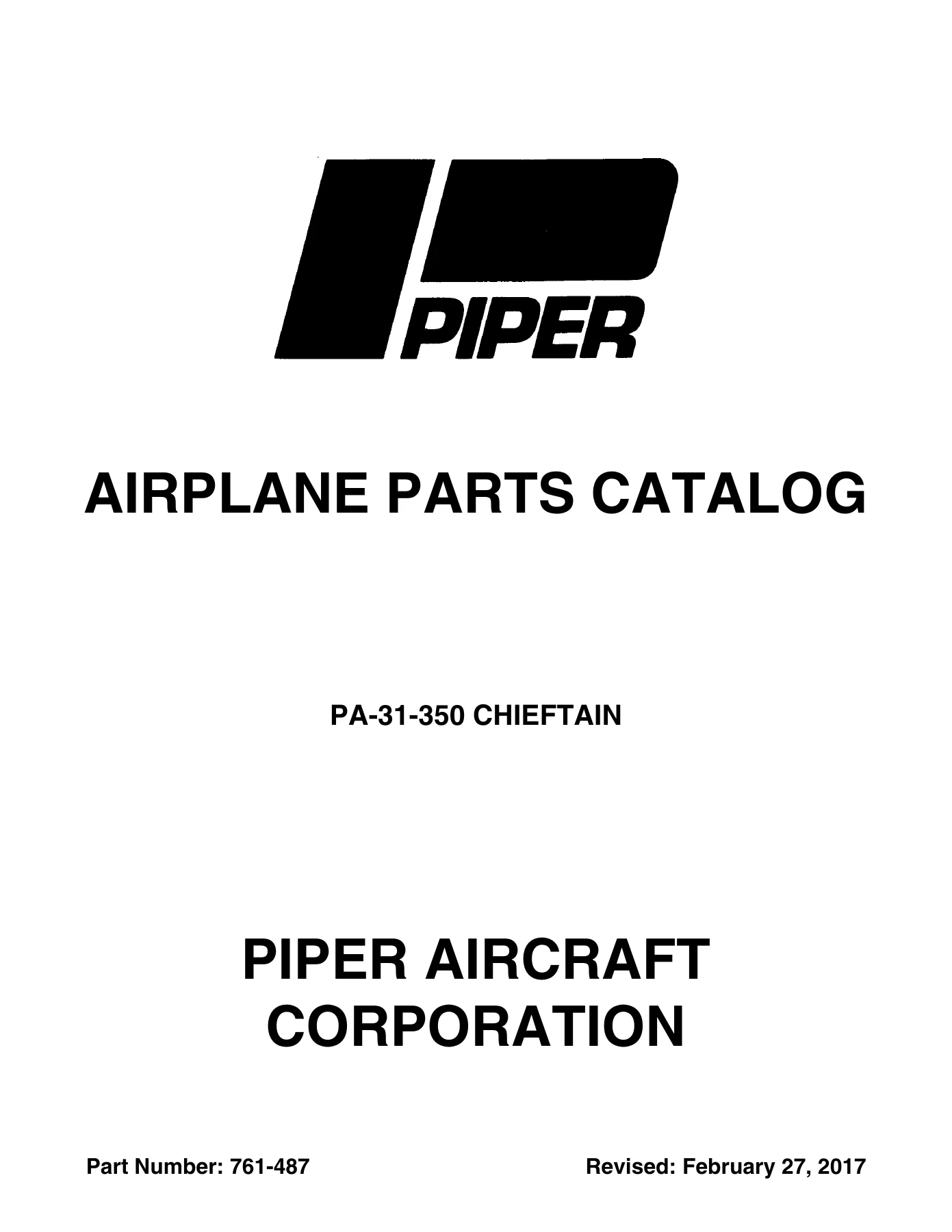
Piper PA-31-350 Chieftain Illustrated Parts Catalog Manual 2017 PDF — PDF page 1 preview
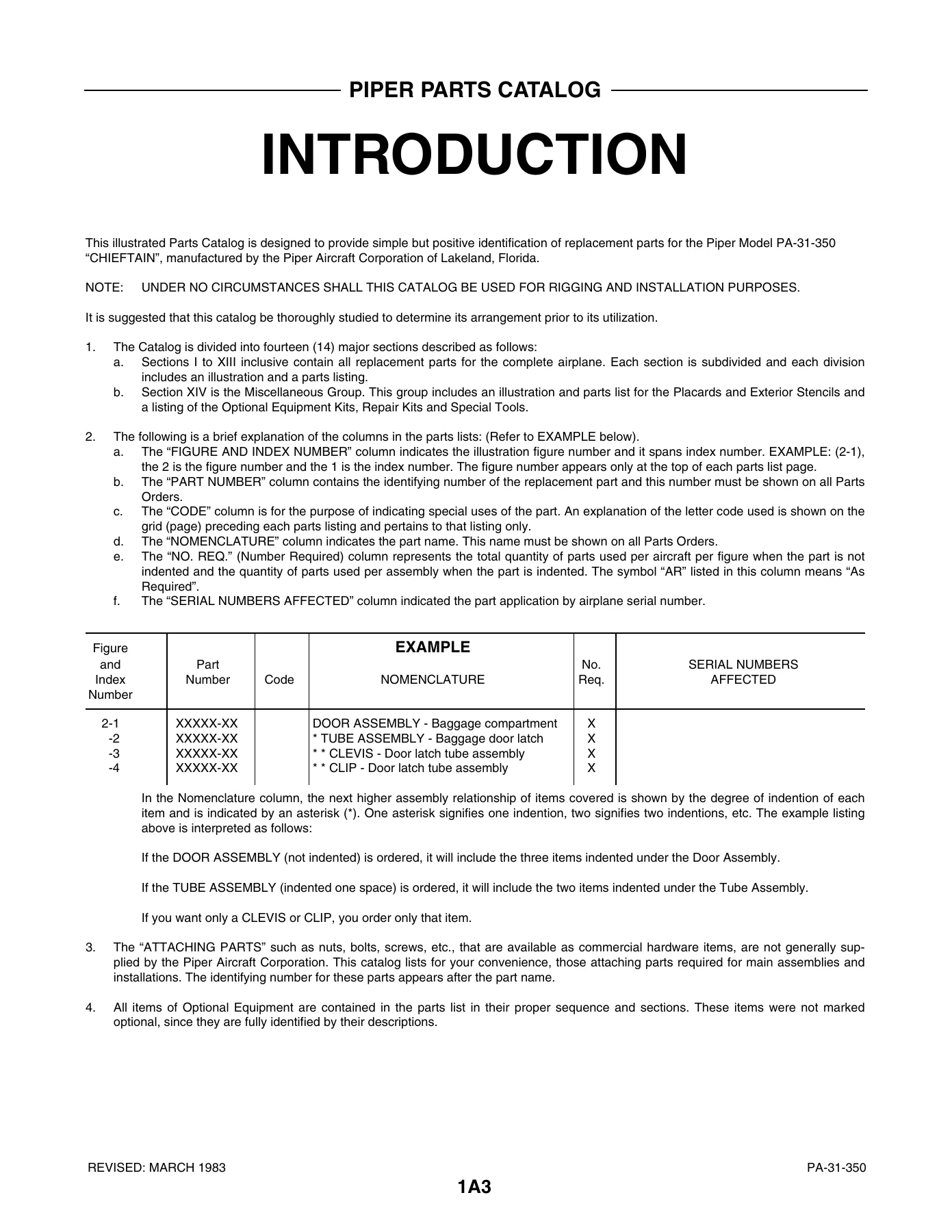
Piper PA-31-350 Chieftain Illustrated Parts Catalog Manual 2017 PDF — PDF page 4 preview
Piper PA-31-350 Chieftain Illustrated Parts Catalog Manual 2017 PDF — PDF page 34 preview

Why This Manual is Indispensable

The Piper PA-31-350 Chieftain is a complex aircraft, and having the correct part numbers is critical for every maintenance and repair task. Whether you are rebuilding an engine, replacing a control cable, upgrading avionics, or simply performing routine maintenance and need a replacement part, this catalog provides the precise information needed to order the correct Piper part. It eliminates the guesswork and potential costly errors associated with ordering incorrect components.

With this manual, you can verify part numbers, understand the hierarchical assembly of components, and communicate effectively with Piper parts distributors. For aircraft owners, mechanics, repair stations, and restorers, this is the definitive parts reference for the Chieftain.

Instant Digital Delivery

Your purchase provides immediate access to a high-quality digital copy of the official Piper Parts Catalog. This PDF can be downloaded to your computer, tablet, or smartphone for easy access in the hangar, office, or field. You can print specific pages for reference or keep the entire manual on a portable device, ensuring you always have the information at your fingertips without the bulk of a physical book.
Reviews

There are no reviews yet.

Be the first to review “Piper PA-31-350 Chieftain Illustrated Parts Catalog Manual 2017 PDF”

What Our Customers Say

★★★★★ Live reviews from customers
Loading customer reviews...
0
    0
    Your Cart
    Your cart is emptyReturn to Shop
    🛒
    Recently Purchased
    🕒 verified order