Description
Pratt & Whitney Canada JT15D-5 and JT15D-5R Turbofan Engine Maintenance Manual
The Pratt & Whitney Canada JT15D-5 and JT15D-5R Turbofan Engine Maintenance Manual is a detailed maintenance reference for the JT15D-5 and JT15D-5R engine models. Its procedures address work with the engine installed in the airframe as well as work performed after engine removal, and the manual distinguishes between line maintenance and heavy maintenance tasks. The material extends from routine servicing and external component work through internal engine maintenance, hot section refurbishment, inspection, testing, fault isolation and limited repairs.
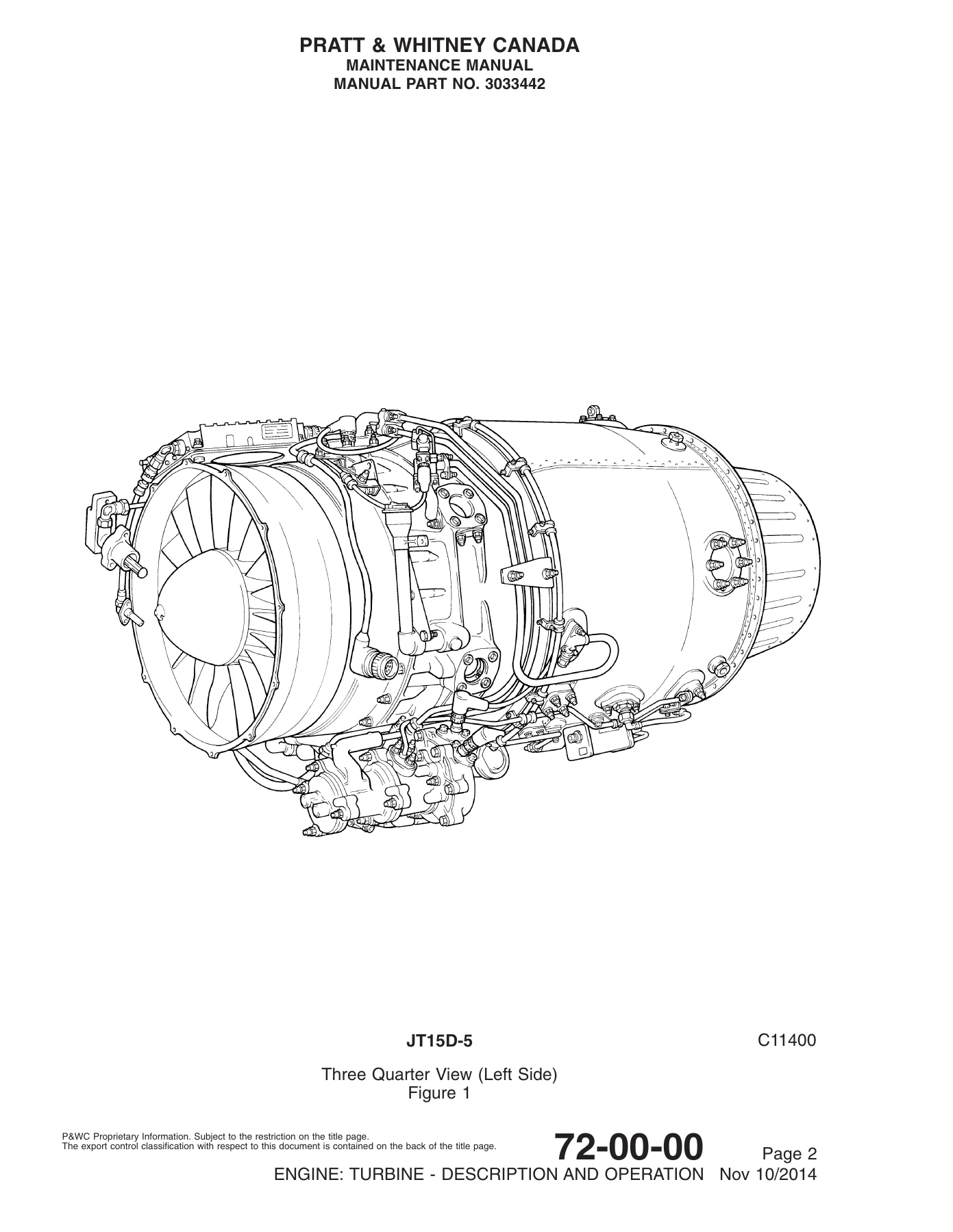
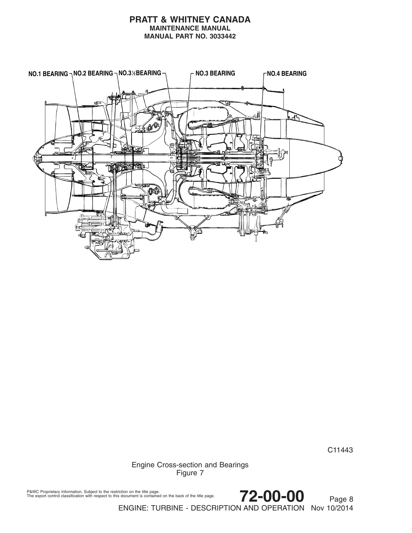
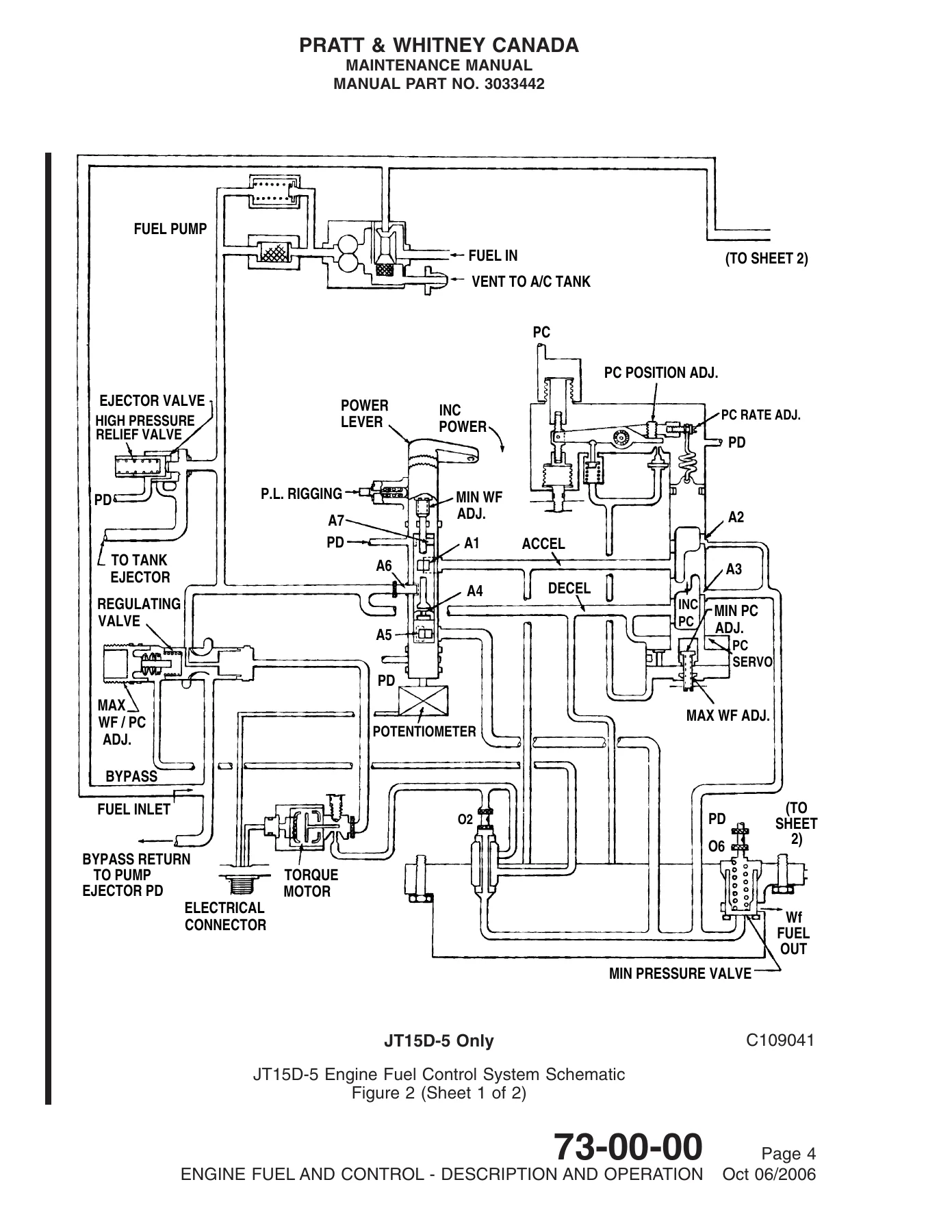
This manual is organized according to ATA chapter, section and subject numbering, giving technicians a structured path through standard practices, power plant testing, turbine engine assemblies, fuel and control equipment, ignition, air systems, engine indicating and lubrication. Detailed procedures are supported by engine illustrations, cross-sections, system diagrams, inspection criteria, special-tool information, service limits, torque data and maintenance practice drawings.
File Details
- Manual type: Maintenance Manual
- Manufacturer: Pratt & Whitney Canada
- Models: JT15D-5 and JT15D-5R
- Engine type: Turbofan engine
- Manual part number: 3033442
- Original issue date: 12 August 1983
- Revision: Revision No. 41, dated Apr 04/2016
- Language: English
- Pages: 1,253
- File format: PDF
Line Maintenance and Heavy Maintenance Coverage
The maintenance concept is divided into two practical levels. Line maintenance covers the removal and installation of external components and engine accessories unless a procedure is specifically identified for heavy maintenance. Heavy maintenance extends into engine internal components, hot section refurbishment and limited repair of hot section components. This makes the JT15D-5 and JT15D-5R maintenance manual useful for both day-to-day engine servicing and more involved shop work where the manual specifically provides an approved maintenance procedure.
Build specification information identifies JT15D-5 configurations including BS636, BS657, BS713 and BS1191, and JT15D-5R configurations BS1220 and BS1221. The manual also explains that it is not customized to one particular airframe installation, so installation-specific differences are addressed where applicable while the engine procedures remain centered on the JT15D-5 and JT15D-5R.
Chapters Covered
- Introduction
- Customer support and maintenance concept
- Supplementary publications and service bulletins
- Build specifications and use of the manual
- Engine part nomenclature, directional references and abbreviations
- Special Tools, Fixtures and Equipment
- Special tools and illustrated tooling
- Torque wrench information and operation
- Supplementary tool information
- Engine test equipment and fixtures
- Consumable Materials
- Fuels, oils, greases, lubricants, sealants, adhesives and cleaning materials
- Consumable material identification and supplier codes
- Airworthiness Limitations
- Rotor component service life limitation information
- 70 – Standard Practices
- Maintenance procedures and torque recommendations
- Removal and installation practices
- Inspection and cleaning
- Welding, blend repairs, studs, inserts and corrosion treatment
- 71 – Power Plant
- Adjustment and test procedures
- Ground safety precautions and engine operating limits
- Engine ground checks, calibration and performance testing
- Fuel manifold pressure checks
- Engine vibration analysis and trim balance
- Fan, compressor and turbine washing and corrosion inhibition
- 72 – Engine: Turbine
- Engine description, operation and engine data
- Fault isolation and electronic fault diagnosis
- Engine oil servicing, storage, shipping, preservation and depreservation
- Engine removal, installation and inspection
- Compressor section
- Combustion section
- Turbine section
- Accessory gearbox
- Bypass section
- 73 – Engine Fuel and Control
- Fuel distribution
- Fuel-to-oil cooler, fuel pump, flow divider valve and fuel manifold
- Fuel drain, flowmeter, pressure and bypass tubes
- Emergency fuel shut-off system and bleed valve actuator
- Fuel filter and JT15D-5R fuel/oil heat exchanger
- Hydromechanical metering unit
- Engine electronic control, wiring harness and sensors
Complete PDF Bookmark Tree
Complete Bookmarks
The complete bookmarks in the “Pratt & Whitney Canada JT15D-5 and JT15D-5R Turbofan Engine Maintenance Manual” are as follows:
+MAINTENANCE MANUAL (3033442)p. 1
REVISION HIGHLIGHTSp. 3
RECORD OF REVISIONSp. 6
RECORD OF TEMPORARY REVISIONSp. 7
LIST OF EFFECTIVE PAGESp. 8
LIST OF CHAPTER/SECTION/SUBJECTSp. 9
TEMPORARY REVISION LISTp. 13
SERVICE BULLETIN LISTp. 14
TABLE OF CONTENTSp. 20
+INTRODUCTIONp. 21
List of Effective Pagesp. 21
Table of Contentsp. 23
+INTRODUCTIONp. 25
1. Generalp. 25
2. Customer Supportp. 25
+3. Maintenance Conceptp. 26
A. Line Maintenancep. 26
B. Heavy Maintenancep. 26
4. Supplementary Publicationsp. 26
5. Service Bulletinsp. 26
6. Special Tool Service Bulletinsp. 26
7. Suppliers and Supplier Servicesp. 27
8. Build Specification (BS)p. 27
+9. How to Use this Manualp. 27
A. Chapter/Section/Subject Numberingp. 27
10. Engine Part Nomenclaturep. 28
11. Directional Referencesp. 28
12. Abbreviationsp. 28
+SPECIAL TOOLS/FIXTURES AND EQUIPMENTp. 31
+1. Special Toolsp. 31
A. Generalp. 31
B. Ordering Special Toolsp. 31
2. Special Toolsp. 31
+3. Torque Wrenchp. 54
A. Generalp. 54
B. Torque Wrench PWC31050p. 54
C. PWC31050 Operationp. 54
D. Torque Wrench PWC41050p. 55
4. Supplementary Tool Informationp. 55
5. Special Fixtures and Equipmentp. 62
+CONSUMABLE MATERIALSp. 68
+1. Consumable Materialsp. 68
A. Generalp. 68
B. Consumable Material Tablep. 68
+2. Consumable Materialsp. 70
+AIRWORTHINESS LIMITATIONSp. 98
List of Effective Pagesp. 98
Table of Contentsp. 99
+AIRWORTHINESS LIMITATIONSp. 100
+CHAPTER 70 – STANDARD PRACTICESp. 102
+70-00 Standard Practicesp. 102
List of Effective Pagesp. 102
Table of Contentsp. 103
+STANDARD PRACTICES – MAINTENANCE PROCEDURESp. 108
1. Generalp. 108
2. Consumable Materialsp. 108
3. Special Toolsp. 109
4. Fixtures, Equipment and Supplier Toolsp. 109
5. Generalp. 109
+6. Special Limits and Torque Recommendationsp. 110
A. Generalp. 110
B. Terms and Symbolsp. 110
+7. Standard Torquesp. 111
A. Torque Limit Valuesp. 111
B. Lubricantsp. 111
C. Tightening Proceduresp. 112
D. Torque Check For Reuse Of Self-Locking Fastenersp. 112
+8. Torque Indicating Devicesp. 113
A. Generalp. 113
B. Torque Wrench and Extensionsp. 113
+9. Torque Recommendationsp. 115
A. Generalp. 115
B. Antiseize Lubricated Partsp. 115
C. Nuts, Bolts and Screwsp. 115
D. Self-locking Nutsp. 116
E. Lockwire and Cotterpin Requirementsp. 116
F. Slotted, Steel Locknuts (Prevailing Torque Type)p. 116
G. Standard and Stepped Studsp. 116
H. Hose, Tubing and Threaded Couplingsp. 116
+10. Locking Devicesp. 116
A. Generalp. 116
B. Keywashers (Tab and Cup Type)p. 116
C. Retaining Ringsp. 117
D. Installing Lockwirep. 117
E. Installing Safety Cablep. 119
11. Identification of Hardware Material, Particularly Nuts and Boltsp. 135
12. Stainless Steel Bolts with Reduced Pitch Diametersp. 137
+13. Identification of Metal Particlesp. 139
A. Generalp. 139
B. Test Procedurep. 139
C. Test Procedure for Identification of Titanium Particlesp. 140
+14. Marking of Partsp. 141
A. Generalp. 141
B. Permanent Marking Methodsp. 141
C. Temporary Marking Methodsp. 142
+STANDARD PRACTICES – REMOVAL/INSTALLATIONp. 144
1. Generalp. 144
2. Consumable Materialsp. 144
3. Special Toolsp. 144
4. Fixtures, Equipment and Supplier Toolsp. 144
+5. Removal/Installationp. 144
A. General Removal and Installation Practicesp. 144
B. Removal of Straight Nipples, Straight Adapters, Bulkhead Couplings and Tube Connector Nipples.p. 145
C. Removal of Tube-to-Boss Elbows, Elbow Adapters and Elbow Assembliesp. 145
D. Lubrication of Preformed Packingsp. 146
E. Installation of Straight Nipples, Straight Adapters, Bulkhead Couplings and Tube Connector Nipplesp. 146
F. Installation of Tube-to-Boss Elbows, Elbow Adapters and Elbow Assembliesp. 146
+STANDARD PRACTICES – INSPECTIONp. 150
1. Generalp. 150
2. Consumable Materialsp. 150
3. Special Toolsp. 150
4. Fixtures, Equipment and Supplier Toolsp. 150
+5. Inspectionp. 150
A. Standard Checksp. 150
B. Inspection Gagesp. 151
C. Inspection of Fuel, Oil and Air Filtersp. 151
D. Inspection of Welded Repairsp. 151
E. Inspection of Fuel, Oil and Air Tubesp. 151
F. Inspection of Rotating Componentsp. 153
+STANDARD PRACTICES – CLEANINGp. 159
1. Generalp. 159
2. Consumable Materialsp. 159
3. Special Toolsp. 159
4. Fixtures, Equipment and Supplier Toolsp. 159
+5. Cleaningp. 159
A. General Precautionsp. 159
B. Cleaning Precautionsp. 159
C. Cleaning Before Weldingp. 160
+STANDARD PRACTICES – REPAIRp. 161
1. Generalp. 161
2. Consumable Materialsp. 161
3. Special Toolsp. 161
4. Fixtures, Equipment and Supplier Toolsp. 161
+5. Welding Repairsp. 162
A. Generalp. 162
B. Welding Equipmentp. 162
C. Cleaning Before Weldingp. 162
D. Welding Proceduresp. 162
E. Cleaning After Weldingp. 163
F. Local Stress Reliefp. 164
G. Inspection of Weldingp. 164
H. Blend Repair Procedurep. 164
+6. Blend Repairsp. 164
A. Blend Repair Procedurep. 164
+7. Helical Coil Insertsp. 164
A. Replacement of Helical Coil Insertsp. 164
+8. Studsp. 165
A. Replacement of Studsp. 165
B. Repair of Damaged Stud Holep. 166
+9. Corrosion Treatmentp. 167
A. Magnesium Alloy Componentsp. 167
+10. Shanknutsp. 168
+CHAPTER 71 – POWER PLANTp. 170
+71-00 Power Plantp. 170
List of Effective Pagesp. 170
Table of Contentsp. 172
+POWER PLANT – ADJUSTMENT/TESTp. 176
1. Generalp. 176
2. Consumable Materialsp. 176
3. Special Toolsp. 176
4. Fixtures, Equipment and Supplier Toolsp. 176
5. Introductionp. 178
+6. Ground Safety Precautionsp. 178
A. Generalp. 178
B. Air Intake Area – Engine Runningp. 178
C. Exhaust Jet Wake Area – Engine Runningp. 178
D. Cool Downp. 180
E. Jet Fuel and Lubricating Oilp. 180
+7. Test Informationp. 180
A. Generalp. 180
B. Symbolsp. 180
C. Instrument Accuracyp. 180
8. Engine Operating Limitsp. 181
9. Engine Data Plate Informationp. 182
10. Engine Overtemperature Conditionp. 183
11. Engine Overspeed Conditionp. 185
12. Foreign Object Damage (FOD)p. 185
+13. EEC Reversionp. 190
A. Engine Electronic Control (EEC) Reversionp. 190
14. Fuelp. 190
15. Precipitationp. 190
+16. Fuel Manifold Pressure Checks – Recommendationsp. 190
A. Generalp. 190
B. Secondary Fuel Manifold Pressure Checkp. 191
C. Primary Fuel Manifold Pressure Checkp. 191
+17. Extreme Weather Conditionsp. 192
A. Cold Weather Proceduresp. 192
B. Hot Weather Proceduresp. 192
18. Ground Testingp. 193
+19. Engine Ground Checksp. 194
A. Check No. 1 – Premotoring or Prestartp. 194
B. Dry Motoring Runp. 194
C. Wet Motoring Runp. 195
D. Emergency – Ground Engine Firep. 196
E. Check No. 2 – Engine Startp. 196
F. Check No. 3 – Engine Shutdownp. 198
G. Check No.4 – Engine Calibrationp. 199
H. Check No. 5 – Engine Performancep. 203
I. Check No.6 – EEC Authorityp. 205
J. Check No.7 – Minimum Fuel Flowp. 210
K. Check No. 8 – Secondary Fuel Manifold Pressure Check JT15D-5 (Pre-SB7493 and Pre-SB7526)p. 212
L. Primary Fuel Manifold Pressure Checkp. 219
M. Check No.9 – N1 Takeoff Thrust Checkp. 221
N. Check 10 – Fuel Pump Inlet Screen Checkp. 224
+20. On-Aircraft Engine Vibration Analysis and Trim Balancep. 224
+21. On Aircraft Engine Vibration Analysis and Trim Balance using ACES Model 1700 Equipmentp. 225
A. Check Engine LP Compressor Trim Balance Weight Configurationp. 225
B. Installation of ACES Model 1700 Equipmentp. 227
C. Check ACES Model 1700 Battery Chargep. 234
D. Reviewing, Storing and Compressing Previous Vibration Surveysp. 234
E. Engine Vibration Survey: ACES Model 1700p. 235
F. Reference Fan Trim Balancing Run: ACES Model 1700p. 237
G. Trial Counterweight Fan Trim Balance Run: ACES Model 1700p. 240
H. Final Trim Counterweight Fan Balance Run: ACES Model 1700p. 241
I. Review Trim Balance Resultsp. 242
J. Removal of Test Equipmentp. 242
+22. Use of Chadwick-Helmuth Model 8500 Equipmentp. 243
A. On Aircraft Engine Vibration Analysis and Trim Balance – Chadwick-Helmuth Model 8500p. 243
+POWER PLANT – CLEANINGp. 248
1. Generalp. 248
2. Consumable Materialsp. 248
3. Special Toolsp. 248
4. Fixtures, Equipment and Supplier Toolsp. 248
+5. Cleaning Proceduresp. 248
A. Generalp. 248
B. Recommended Wash Methods and Intervalsp. 249
+6. Engine External Washp. 250
A. Engine External Washp. 250
+7. Engine Preparationp. 250
A. Procedurep. 250
B. Preparation of Equipmentp. 251
+8. Fan Washingp. 251
+9. Compressor Desalination Washp. 253
A. Compressor Desalination Motoring Washp. 253
+10. Turbine Washingp. 254
+11. Post-Wash Proceduresp. 256
+12. Inhibition of Engine Corrosionp. 257
A. Optional On-aircraft Internal Application of Engine Corrosion-inhibiting Solutionp. 257
B. Optional On-aircraft External Application of Engine Corrosion-inhibiting Solutionp. 258
+CHAPTER 72 – ENGINEp. 259
+72-00 Engine: Turbinep. 259
List of Effective Pagesp. 259
Table of Contentsp. 262
+ENGINE: TURBINE – DESCRIPTION AND OPERATIONp. 267
1. Generalp. 267
+2. Engine Datap. 277
A. Engine Specifications and Leading Particularsp. 277
B. Engine-Driven Accessories – Leading Particularsp. 277
C. Fuel and Lubrication System Specifications and Leading Particularsp. 278
+ENGINE: TURBINE – FAULT ISOLATIONp. 282
+1. Generalp. 282
A. Discovering the Faultp. 282
B. Isolating Engine Faultsp. 282
C. Mechanical Integrityp. 282
+2. Electronic Fault Diagnosisp. 282
A. The JEDA Kit Contentsp. 282
B. JEDA Kit Preparation and Storagep. 283
C. Electronic Fault Diagnosis Procedurep. 283
D. Operating the Model 560 PDAp. 283
E. Review Data Display with PDAp. 285
F. PLA Rigging Checksp. 286
G. Data Review with Engine Runningp. 287
3. Fault Isolationp. 288
+ENGINE: TURBINE – SERVICINGp. 348
1. Generalp. 348
2. Consumable Materialsp. 348
3. Special Toolsp. 348
4. Fixtures, Equipment and Supplier Toolsp. 348
+5. Servicing the Engine Oil Systemp. 349
A. Engine Oil Filter Elementp. 349
B. Engine Lubricating Oilp. 349
C. Substitution of Engine Lubricating Oilp. 349
D. Blue Oil Dyep. 349
E. Oil Analysisp. 350
F. Oil Level Checkp. 351
G. Draining Oil Systemp. 352
H. Filling Oil Systemp. 352
I. Flushing Oil Systemp. 354
+6. Storage and Shippingp. 355
A. Engine Shipping Container – Descriptionp. 355
B. Engine Shipping Container – Humidity Controlp. 355
C. Reactivation of Desiccant and Humidity Indicatorp. 355
D. Engine Handling Precautionsp. 356
E. Removal of Engine from Shipping Containerp. 356
F. Installation of Engine into Shipping Containerp. 360
+7. Engine Preservation and Depreservationp. 363
A. Engine Preservation Recommendationsp. 363
B. Engine Preservation Schedulep. 364
C. Application of Corrosion-Inhibiting Compound to Engine External Areasp. 366
D. Preservation of Engine Fuel Systemp. 366
E. Preservation of Engine Oil Systemp. 367
F. Engine Depreservation Schedulep. 368
G. Depreservation of Engine Oil Systemp. 369
H. Depreservation of Engine Fuel Systemp. 369
I. Regular Operation as an Alternative to the Preservation of Enginesp. 370
+8. Removal/Installation of Engine from/into Maintenance Standp. 370
A. Installation of Engine in Standp. 370
B. Removal of Engine from Standp. 372
+9. Inhibition of Engine Corrosionp. 373
A. Generalp. 373
B. Recommended Procedures for External and Internal Engine Corrosion Inhibitionp. 373
C. Recommended Procedures for Engine Corrosion Inhibition During Long-term Storagep. 373
+ENGINE: TURBINE – REMOVAL/INSTALLATIONp. 374
1. Generalp. 374
2. Consumable Materialsp. 374
3. Special Toolsp. 374
4. Fixtures, Equipment and Supplier Toolsp. 374
+5. Removal of Engine from Airframep. 374
A. Generalp. 374
B. Procedurep. 374
C. Disposition of Engine Following Removal from Airframe and Installation in Maintenance Standp. 375
+6. Preparation of Engine Removed from or Installed in Airframep. 376
A. Generalp. 376
B. Preparation of Front Mount Padsp. 376
C. Preparation of Rear Engine Mountp. 376
D. Relocation of Oil Filler Neckp. 379
E. Installation Requirements for Cabin Bleed Air Transfer Tubep. 380
+7. Installation of Engine in Airframep. 382
+ENGINE: TURBINE – INSPECTIONp. 385
1. Generalp. 385
2. Consumable Materialsp. 385
3. Special Toolsp. 385
4. Fixtures, Equipment and Supplier Toolsp. 385
5. Corrosionp. 385
6. Control Linkagep. 386
7. Periodic Inspectionp. 386
+8. Hot Section Inspectionp. 391
+9. Special Conditions Inspectionp. 403
A. Engine Overtemperaturep. 403
B. Foreign Object Damage (FOD)p. 403
C. Loss of Oilp. 405
D. Engine Overspeedp. 406
E. Engine Windmillingp. 406
F. Engine Immersion in Waterp. 406
G. Engine Dropped During Handlingp. 406
H. Lightning Strikep. 407
I. Engine Exposed to Fire Extinguishing Agentp. 407
J. Heavy/Hard Landingp. 407
K. Aircraft Flown Through a Cloud of Volcanic Ashp. 408
L. Starter Generator Fail Indicationp. 408
+10. Borescope Inspectionp. 409
A. Generalp. 409
B. Descriptionp. 410
C. Basic Use of Borescopep. 410
D. Removal /Installation of Side Viewing Adapterp. 410
E. Removal/Installation of Camerap. 410
F. LP Compressor Boost Stage Rotor and Front Inner Statorp. 410
G. Impellerp. 413
H. Fuel Nozzles, Combustion Chamber and Large Exit Ductp. 413
I. No. 4 Bearing Housing/Overspeed Control Linkagep. 415
J. HP Turbine Bladesp. 419
K. Fault Isolationp. 419
+72-30 Compressor Sectionp. 423
List of Effective Pagesp. 423
Table of Contentsp. 425
+COMPRESSOR SECTION – DESCRIPTION AND OPERATIONp. 429
1. Compressor Sectionp. 429
+LP COMPRESSOR CASE AND STATORS – DESCRIPTION AND OPERATIONp. 430
1. LP Compressor Case and Stator Assembliesp. 430
+LP COMPRESSOR CASE AND STATORS – MAINTENANCE PRACTICESp. 431
1. Generalp. 431
2. Consumable Materialsp. 431
3. Special Toolsp. 431
4. Fixtures, Equipment and Supplier Toolsp. 431
+5. Removal/Installation (Heavy Maintenance only)p. 431
A. Removal of LP Compressor Case and Front Stator Assembliesp. 431
B. Installation of LP Compressor Case and Stator Assembliesp. 437
+6. Cleaning/Paintingp. 440
A. Generalp. 440
B. Compressor Washp. 440
+7. Inspection/Checkp. 441
A. LP Compressor Casep. 441
B. LP Compressor Front Stator Assembly and Retaining Rivetsp. 441
+8. Approved Repairsp. 443
A. LP Compressor Case – Blade Rub Repairp. 443
B. LP Compressor Stator Assemblyp. 443
C. LP Compressor Stator Assembly – Rivet Replacementp. 443
9. Fits, Clearances and Torque Loadingsp. 443
+INTERMEDIATE CASE ASSEMBLY – DESCRIPTION AND OPERATIONp. 448
+INTERMEDIATE CASE ASSEMBLY – MAINTENANCE PRACTICESp. 450
1. Generalp. 450
2. Consumable Materialsp. 450
3. Special Toolsp. 450
4. Fixtures, Equipment and Supplier Toolsp. 450
+5. Approved Repairsp. 450
A. Engine Mount Pads – Threaded Insertsp. 450
B. Corrosionp. 450
+LP COMPRESSOR ROTOR ASSEMBLIES- DESCRIPTION AND OPERATIONp. 452
+1. Descriptionp. 452
A. LP Compressor Rotor Assembliesp. 452
B. Compressor Inlet Conep. 452
+LP COMPRESSOR ROTOR – MAINTENANCE PRACTICESp. 454
1. Generalp. 454
2. Consumable Materialsp. 454
3. Special Toolsp. 454
4. Fixtures, Equipment and Supplier Toolsp. 455
+5. Removal/Installation (Heavy Maintenance Only)p. 456
A. Removal of Inlet Cone Assemblyp. 456
B. Installation of Inlet Cone Assemblyp. 458
C. Removal of LP Compressor Rotorp. 458
D. Installation of LP Compressor Rotorp. 460
E. Installation and Balance Weight Coding for Replacement, Serviced or Repaired LP Compressor Rotorp. 465
+6. Adjustment/Testp. 467
A. On-Wing Engine Vibration Analysis and Trim Balancep. 467
+7. Inspection/Checkp. 467
A. Inspection of Inlet Conep. 467
B. LP Compressor Booster Stage Rotor Blade Inspectionp. 468
C. Inspection of LP Compressor Rotor Bladesp. 468
+8. Approved Repairsp. 472
A. LP Compressor Bladesp. 472
+9. Fits, Clearances and Torque Loadingsp. 473
+NO.1 BEARING AND N1 SPEED SENSING – DESCRIPTION AND OPERATIONp. 477
1. LP Compressor Shaft, No.1 Bearing and N1 Speed Sensingp. 477
+GAS GENERATOR CASE – DESCRIPTION AND OPERATIONp. 480
+GAS GENERATOR CASE – MAINTENANCE PRACTICESp. 482
1. Generalp. 482
2. Consumable Materialsp. 482
3. Special Toolsp. 482
4. Fixtures, Equipment and Supplier Toolsp. 482
+5. Inspection/Checkp. 482
+HIGH PRESSURE COMPRESSOR ASSEMBLY – DESCRIPTION AND OPERATIONp. 484
+HIGH PRESSURE COMPRESSOR ASSEMBLY – MAINTENANCE PRACTICESp. 486
1. Generalp. 486
2. Consumable Materialsp. 486
3. Special Toolsp. 486
4. Fixtures, Equipment and Supplier Toolsp. 486
+5. Inspection/Checkp. 486
+LP COMPRESSOR BLEED AIR SYSTEM – DESCRIPTION AND OPERATIONp. 488
1. Compressor Bleed Systemp. 488
2. Bleed System Operationp. 488
+COMPRESSOR BLEED VALVE – MAINTENANCE PRACTICESp. 491
1. Generalp. 491
2. Consumable Materialsp. 491
3. Special Toolsp. 491
4. Fixtures, Equipment and Supplier Toolsp. 491
+5. Adjustment/Testp. 491
A. Rigging of Bleed Valve :p. 491
+72-40 Combustion Sectionp. 496
List of Effective Pagesp. 496
Table of Contentsp. 497
+COMBUSTION SECTION – DESCRIPTION AND OPERATIONp. 498
1. Combustion Sectionp. 498
+COMBUSTION CHAMBER, LPT ST. SUPPORT- DESCRIPTION AND OPERATIONp. 500
1. Combustion Chamber Linerp. 500
2. LP Turbine Stator Supportp. 500
+COMBUSTION CHAMBER, LPT STATOR SUPPORT – MAINTENANCE PRACTICESp. 503
1. Generalp. 503
2. Consumable Materialsp. 503
3. Special Toolsp. 503
4. Fixtures, Equipment and Supplier Toolsp. 503
+5. Removal/Installation (Heavy Maintenance Only)p. 503
A. Removal of LP Turbine Stator Support Assembly and Combustion Chamber Linerp. 503
B. Pre-assembly of LP Turbine Stator Assembly and Combustion Chamber Linerp. 505
C. Installation of LP Turbine Stator Assembly and Combustion Chamber Linerp. 506
+6. Inspection/Checkp. 507
A. LP Turbine Stator Support Assembly – Wear and Frettingp. 507
B. Combustion Chamber Liner and Support Pinsp. 507
+7. Approved Repairsp. 512
A. Crack Repair by Weldingp. 512
B. Cooling Ring Repairp. 512
8. Fits, Clearances and Torque Loadingsp. 512
+72-50 Turbine Sectionp. 517
List of Effective Pagesp. 517
Table of Contentsp. 520
+TURBINE SECTION – DESCRIPTION AND OPERATIONp. 525
1. High Pressure and Low Pressure Turbinesp. 525
+HPT STATOR, EXIT DUCTS – DESCRIPTION AND OPERATIONp. 528
+1. Descriptionp. 528
A. HP Turbine Stator Assemblyp. 528
B. Large and Small Exit Ductsp. 528
C. HP Turbine Air Sealp. 528
+HPT STATOR, EXIT DUCTS – MAINTENANCE PRACTICESp. 532
1. Generalp. 532
2. Consumable Materialsp. 532
3. Special Toolsp. 532
4. Fixtures, Equipment and Supplier Toolsp. 533
+5. Removal/Installation (Heavy Maintenance Only)p. 533
A. Removal of HP Turbine Stator Assembly, Large and Small Exit Ductsp. 533
B. Installation of HP Turbine Stator Assembly, Large and Small Exit Ductsp. 540
+6. Inspection/Checkp. 544
A. Interstage Seal Ringp. 544
B. High Pressure Turbine Air Seal and Bafflep. 544
C. Shroud Segmentsp. 544
D. Small Exit Ductp. 545
E. HP Turbine Stator Sealing Ringp. 552
F. High Pressure Turbine Stator Assemblyp. 552
G. Large Exit Ductp. 557
+7. Approved Repairsp. 557
A. HP Turbine Stator Assembly – Repairability Criteriap. 557
B. HP Turbine Shroud Segments – Repair by Replacementp. 559
C. Grinding of HP Turbine Shroud Segmentsp. 560
8. Fits, Clearances and Torque Loadingsp. 567
+HP TURBINE DISK BALANCING ASSEMBLY – DESCRIPTION AND OPERATIONp. 573
+HP TURBINE ASSEMBLY – MAINTENANCE PRACTICESp. 575
1. Generalp. 575
2. Consumable Materialsp. 575
3. Special Toolsp. 575
4. Fixtures, Equipment and Supplier Toolsp. 576
+5. Removal/Installation (Heavy Maintenance Only)p. 576
A. Removal of HP Turbine Disk Assemblyp. 576
B. Installation of HP Turbine Disk Assemblyp. 583
+6. Procedure for Installing Replacement High Pressure Turbinep. 586
A. Establish Trim Balance Weight Configuration for Replacement Turbinep. 586
B. Determine HP Turbine Positioning Spacer Dimension as follows :p. 588
C. Installation Procedurep. 588
+7. Inspection/Checkp. 588
+8. Approved Repairs (Heavy Maintenance Only)p. 592
9. Fits, Clearances and Torque Loadingsp. 592
+LP TURBINE ROTOR BALANCING ASSEMBLY – DESCRIPTION AND OPERATIONp. 600
+LP TURBINE ROTOR – MAINTENANCE PRACTICESp. 603
1. Generalp. 603
2. Consumable Materialsp. 603
3. Special Toolsp. 603
4. Fixtures, Equipment and Supplier Toolsp. 604
+5. Removal/Installation (Heavy Maintenance Only)p. 604
A. Removal of LP Turbine Rotor Balancing and LP Turbine Stator Assembliesp. 604
B. Installation of LP Turbine Rotor Balancing Assembly and LP Turbine Stator Assemblyp. 609
+6. Inspection/Checkp. 612
A. Low Pressure Turbine Rotor Balancing Assemblyp. 612
B. LP Turbine Shaftp. 617
C. Intershaft Oil Transfer Tubep. 617
+7. Cleaning/Paintingp. 620
A. Intershaft Oil Transfer Tube Assemblyp. 620
B. Low Pressure Turbine Shaftp. 621
8. Fits, Clearances and Torque Loadingsp. 621
+SECOND-STAGE LPT STATOR – DESCRIPTION AND OPERATIONp. 625
+SECOND-STAGE LPT STATOR – MAINTENANCE PRACTICESp. 627
1. Generalp. 627
2. Consumable Materialsp. 627
3. Special Toolsp. 627
4. Fixtures, Equipment and Supplier Toolsp. 627
5. Removal/Installation (Heavy Maintenance Only)p. 627
+6. Inspection/Checkp. 627
7. Fits, Clearances and Torque Loadingsp. 630
+THIRD-STAGE LP TURBINE STATOR- DESCRIPTION AND OPERATIONp. 632
+EXHAUST DUCT, NO. 4 BEARING HOUSING – DESCRIPTION AND OPERATIONp. 633
+ENGINE CONTROLS – FAULT ISOLATIONp. 635
+EXHAUST DUCT ASSEMBLY – MAINTENANCE PRACTICESp. 636
1. Generalp. 636
2. Consumable Materialsp. 636
3. Special Toolsp. 636
4. Fixtures, Equipment and Supplier Toolsp. 636
+5. Removal/Installation (Heavy Maintenance Only)p. 636
A. Removal of Turbine Exhaust Ductp. 636
B. Installation of Turbine Exhaust Ductp. 637
C. Removal of No. 4 Bearing Housing and Cover Assemblyp. 643
D. Installation of No. 4 Bearing Housing and Cover Assemblyp. 643
E. Removal of Emergency Fuel Shutoff Valve Control Linkagep. 649
F. Installation of Emergency Fuel Shutoff Valve Control Linkagep. 658
G. Disassembly of No. 4 Bearing Housing and Coverp. 664
H. Assembly of No. 4 Bearing Housing and Coverp. 665
+6. Inspection/Checkp. 667
A. Exhaust Ductp. 667
B. Exhaust Duct Borescope Plug Lockwire Tabp. 667
C. No. 4 Bearing Housingp. 668
D. No. 4 Bearing Housing Cover Assemblyp. 668
E. No. 4 Bearing Housing/Exhaust Duct Lug Mating Facesp. 671
F. Exhaust Duct T6 Thermocouple Installationp. 671
G. No. 4 Bearing Oil Nozzle Strainer Elementp. 671
H. Actuating Rodp. 671
+7. Cleaning and Paintingp. 673
A. No. 4 Bearing Housingp. 673
B. No. 4 Bearing Housing Coverp. 674
C. No. 4 Bearing Oil Nozzle Strainer Elementp. 675
D. Actuating Rodp. 675
+8. Approved Repairsp. 675
A. Exhaust Duct – Cracksp. 675
B. Exhaust Duct – Repair for Borescope Plug Lockwire Tab by Replacementp. 676
C. No. 4 Bearing Carbon Seal – Repair by Replacementp. 676
9. Fits, Clearances and Torque Loadingsp. 678
+72-60 Accessory Gearboxp. 689
List of Effective Pagesp. 689
Table of Contentsp. 690
+ACCESSORY DRIVES – DESCRIPTION AND OPERATIONp. 692
1. Engine Accessory Drives )p. 692
+ACCESSORY GEARBOX AND DRIVESHAFT – DESCRIPTION AND OPERATIONp. 694
+1. Accessory Gearbox Assembly and Driveshaftp. 694
+ACCESSORY GEARBOX AND DRIVESHAFT – MAINTENANCE PRACTICESp. 695
1. Generalp. 695
2. Consumable Materialsp. 695
3. Special Toolsp. 695
4. Fixtures, Equipment and Supplier Toolsp. 695
+5. Removal/Installationp. 695
A. Removal of Accessory Gearbox (AGB)p. 695
B. Removal of Engine Identification and Trim Platesp. 701
C. Installation of Engine Identification and Trim Plates on Replacement AGBp. 701
D. Installation of Accessory Gearbox (AGB)p. 701
+6. Inspection/Checkp. 704
7. Fits, Clearances and Torque Loadingsp. 704
+AGB EXTERNALS AND OIL PUMP – DESCRIPTION AND OPERATIONp. 706
+AGB EXTERNALS AND OIL PUMP- MAINTENANCE PRACTICESp. 709
1. Generalp. 709
2. Consumable Materialsp. 709
3. Special Toolsp. 709
4. Fixtures, Equipment and Supplier Toolsp. 709
+5. Removal/Installationp. 709
A. Removal of Oil Pumpp. 709
B. Installation of Oil Pumpp. 713
C. Removal of Accessory Drive Sealsp. 714
D. Installation of Accessory Drive Sealsp. 715
E. Removal of Centrifugal Breather Gearshaft Carbon-Face Sealp. 717
F. Installation of Centrifugal Breather Gearshaft Carbon-Face Sealp. 717
G. Removal of Starter-Generatorp. 719
+6. Cleaning/Paintingp. 719
A. Oil Pump Inlet Strainer Sleevep. 719
+7. Approved Repairsp. 719
A. Oil Pump – Repair by Replacementp. 719
B. Repair of Corrosion – Accessory Gearbox Housingp. 720
8. Fits, Clearances and Torque Loadingsp. 721
+72-70 Bypass Sectionp. 724
List of Effective Pagesp. 724
Table of Contentsp. 725
+BYPASS SECTION – DESCRIPTION AND OPERATIONp. 728
+FRONT INNER BYPASS DUCT ASSEMBLY – DESCRIPTION AND OPERATIONp. 730
+FRONT INNER BYPASS DUCT ASSEMBLY – MAINTENANCE PRACTICESp. 732
1. Generalp. 732
2. Consumable Materialsp. 732
3. Special Toolsp. 732
4. Fixtures, Equipment and Supplier Toolsp. 732
+5. Removal/Installation (Heavy Maintenance Only)p. 732
A. Removal of Front Inner Bypass Ductp. 732
B. Installation of Front Inner Bypass Ductp. 734
+6. Inspection/Checkp. 734
+7. Approved Repairsp. 734
8. Fits, Clearances and Torque Loadingsp. 736
+REAR INNER BYPASS DUCT ASSEMBLY – DESCRIPTION AND OPERATIONp. 738
+REAR INNER BYPASS DUCT ASSEMBLY – MAINTENANCE PRACTICESp. 740
+1. Removal/Installation (Heavy Maintenance Only)p. 740
A. Removal of Rear Inner Bypass Duct )p. 740
B. Installation of Rear Inner Bypass Duct )p. 740
+2. Inspection/Checkp. 740
+3. Approved Repairsp. 740
A. Cracksp. 740
B. Floating Plate Nuts – Replacementp. 740
4. Fits, Clearances and Torque Loadingsp. 742
+OUTER BYPASS DUCT ASSEMBLY – DESCRIPTION AND OPERATIONp. 746
+1. Descriptionp. 746
A. Generalp. 746
B. PsD Sensing Systemp. 746
+OUTER BYPASS DUCT ASSEMBLY – MAINTENANCE PRACTICESp. 748
1. Generalp. 748
2. Consumable Materialsp. 748
3. Special Toolsp. 748
4. Fixtures, Equipment and Supplier Toolsp. 748
+5. Inspection/Checksp. 748
A. Internal and External Surfacesp. 748
+6. Approved Repairsp. 748
A. Mounting Pad Flanges Exhibiting Bond Separation :p. 748
+ENGINE REAR MOUNT INSTALLATION – DESCRIPTION AND OPERATIONp. 751
+ENGINE REAR MOUNT INSTALLATION – MAINTENANCE PRACTICESp. 752
1. Generalp. 752
2. Consumable Materialsp. 752
3. Special Toolsp. 752
4. Fixtures, Equipment and Supplier Toolsp. 752
+5. Removal/Installation (Heavy Maintenance Only)p. 752
A. Removal of Engine Rear Mountp. 752
B. Installation of Engine Rear Mountp. 754
+6. Inspection/Checkp. 755
7. Fits, Clearances and Torque Loadingsp. 755
+CHAPTER 73 – ENGINE FUEL AND CONTROLp. 759
+73-00 Engine Fuel and Controlp. 759
List of Effective Pagesp. 759
Table of Contentsp. 760
+ENGINE FUEL AND CONTROL – DESCRIPTION AND OPERATIONp. 761
+1. Descriptionp. 761
A. Components (Fuel)p. 761
B. Components (Control)p. 763
C. Operation (General)p. 763
D. JT15D-5R Fuel De-Icing Systemp. 763
+ENGINE FUEL AND CONTROL – FAULT ISOLATIONp. 769
1. Engine Fuel and Control – Fault Isolationp. 769
+73-10 Fuel Distributionp. 770
List of Effective Pagesp. 770
Table of Contentsp. 773
+FUEL-TO-OIL COOLER AND FUEL TUBES – DESCRIPTION AND OPERATIONp. 782
1. Fuel-to-Oil Coolerp. 782
2. JT15D-5R Fuel Tubesp. 782
+FUEL-TO-OIL COOLER – MAINTENANCE PRACTICESp. 785
1. Generalp. 785
2. Consumable Materialsp. 785
3. Special Toolsp. 785
4. Fixtures, Equipment and Supplier Toolsp. 785
+5. Removal/Installationp. 785
A. Removal of the JT15D-5 Oil Coolerp. 785
B. Removal of the JT15D-5R Oil Coolerp. 785
C. Installation of the JT15D-5 Oil Coolerp. 787
D. Installation of the JT15D-5R Oil Coolerp. 789
E. Removal of the JT15D-5 Pressure Fuel Tubes (HMU-to-Oil Cooler-to FDV)p. 789
F. Removal of the JT15D-5R Fuel Filter Fuel Tubesp. 792
G. Removal of the JT15D-5R Oil Cooler Fuel Tubesp. 792
H. Removal of the JT15D-5R Fuel Pump Fuel Tubesp. 797
I. Installation of the JT15D-5 Pressure Fuel Tubes (HMU-to-Oil Cooler-to FDV)p. 799
J. Installation of the JT15D-5R Fuel Pump Fuel Tubesp. 800
K. Installation of the JT15D-5R Oil Cooler Fuel Tubesp. 801
L. Installation of the JT15D-5R Fuel Filter Fuel Tubesp. 803
+6. Adjustment/Testp. 804
A. Oil Cooler – Oil Flow Check and Pressure Checkp. 804
+7. Inspection/Checkp. 804
A. Oil Coolerp. 804
B. Pressure Fuel Tubesp. 805
+8. Cleaning/Paintingp. 805
A. Pressure Fuel Tubesp. 805
+FUEL PUMP – DESCRIPTION AND OPERATIONp. 806
1. Fuel Pumpp. 806
2. Operationp. 806
+FUEL PUMP – MAINTENANCE PRACTICESp. 810
1. Generalp. 810
2. Consumable Materialsp. 810
3. Special Toolsp. 810
4. Fixtures, Equipment and Supplier Toolsp. 810
+5. Servicingp. 810
A. Removal of Filtersp. 810
B. Cleaning and Inspectionp. 810
C. Installation of Filtersp. 814
+6. Removal/Installationp. 814
A. Removal of Fuel Pumpp. 814
B. Installation of Fuel Pumpp. 818
C. Removal of the Overtemperature Popup Indicator (JT15D-5R)p. 818
D. Installation of the Overtemperature Popup Indicator (JT15D-5R)p. 818
+7. Inspection/Checkp. 820
8. Adjustment/Testp. 820
+9. Cleaning/Paintingp. 820
+FUEL TUBES, FDV TO FUEL MANIFOLD – DESCRIPTION AND OPERATIONp. 821
1. Manifold Pressure Fuel Tubesp. 821
+FUEL TUBES, FDV TO FUEL MANIFOLD – MAINTENANCE PRACTICESp. 822
1. Generalp. 822
2. Consumable Materialsp. 822
3. Special Toolsp. 822
4. Fixtures, Equipment and Supplier Toolsp. 822
+5. Removal/Installation (Heavy Maintenance Only)p. 822
A. Removal of Primary and Secondary Pressure Fuel Transfer Tubesp. 822
B. Installation of Primary and Secondary Pressure Fuel Transfer Tubesp. 822
+6. Inspection/Checkp. 825
A. Inspect fuel pressure tube as follows:p. 825
+7. Cleaning/Paintingp. 825
A. Clean pressure fuel tube as follows:p. 825
8. Fits, Clearances and Torque Loadingsp. 825
+FLOW DIVIDER VALVE – DESCRIPTION AND OPERATIONp. 828
1. Flow Divider Valve )p. 828
+FLOW DIVIDER VALVE – MAINTENANCE PRACTICESp. 830
1. Generalp. 830
2. Consumable Materialsp. 830
3. Special Toolsp. 830
4. Fixtures, Equipment and Supplier Toolsp. 830
+5. Removal/Installationp. 830
A. Removal of Flow Divider Valve (FDV)p. 830
B. Installation of Flow Divider Valvep. 830
+FUEL MANIFOLD ASSEMBLY – DESCRIPTION AND OPERATIONp. 835
+1. Descriptionp. 835
A. Fuel Manifoldp. 835
B. Fuel Manifold Adapter Assembliesp. 835
C. Fuel Nozzlesp. 835
2. Operationp. 837
+FUEL MANIFOLD ASSEMBLY – MAINTENANCE PRACTICESp. 841
1. Generalp. 841
2. Consumable Materialsp. 841
3. Special Toolsp. 841
4. Fixtures, Equipment and Supplier Toolsp. 841
+5. Removal/Installationp. 842
A. Removal of Fuel Manifold Assemblyp. 842
+B. Installation of Fuel Manifold Assemblyp. 847
Temporary Revision No. 73-3p. 848
+6. Adjustment/Testp. 851
A. Generalp. 851
B. Functional Test of Fuel Manifold Nozzle Adaptersp. 852
C. JT15D-5 (Pre-SB7598) Fuel Manifold Leak Test using PWC30186 Test Rigp. 858
D. Fuel Manifold Leak Test for JT15D-5 (Post-SB7598) and JT15D-5R Nozzle Adapter Assembliesp. 858
+7. Inspection/Checkp. 860
A. Fuel Nozzle Assemblyp. 860
+8. Cleaning/Paintingp. 860
A. Fuel Nozzle Assemblies:p. 860
+9. Approved Repairsp. 861
A. Fuel Manifold Inlet and Automatic Fuel Shut-off Valve Assembly – Repair by Replacementp. 861
B. Fuel Manifold Adapter Assembliesp. 862
10. Fits, Clearances and Torque Loadingsp. 866
+FUEL DRAIN VALVE – DESCRIPTION AND OPERATIONp. 869
1. Fuel Drain Valvep. 869
+FUEL DRAIN VALVE – MAINTENANCE PRACTICESp. 870
1. Generalp. 870
2. Consumable Materialsp. 870
3. Special Toolsp. 870
4. Fixtures, Equipment and Supplier Toolsp. 870
+5. Removal/Installationp. 870
A. Removal of Gas Generator Case Fuel Drain Valvep. 870
B. Installation of Gas Generator Case Fuel Drain Valvep. 870
C. Exhaust Area Fuel Drainp. 872
+FUEL FLOWMETER INSTALLATION – DESCRIPTION AND OPERATIONp. 873
+FUEL FLOWMETER INSTALLATION – MAINTENANCE PRACTICESp. 875
1. Removal/Installationp. 875
+FUEL PRESSURE AND BYPASS TUBES – DESCRIPTION AND OPERATIONp. 876
1. External Pressure and Bypass Fuel Tubesp. 876
+FUEL PRESSURE AND BYPASS TUBES – MAINTENANCE PRACTICESp. 877
1. Generalp. 877
2. Consumable Materialsp. 877
3. Special Toolsp. 877
4. Fixtures, Equipment and Supplier Toolsp. 877
+5. Removal/Installationp. 877
A. Removal of Primary and Secondary Pressure Fuel Tubes and Bypass Tubep. 877
B. Installation of Primary and Secondary Pressure Fuel Tubes and Bypass Tubep. 877
+6. Inspection/Checkp. 881
+7. Cleaning/Paintingp. 881
A. Pressure Fuel Tubesp. 881
+HP COMPRESSOR AIR DELIVERY TUBES – DESCRIPTION AND OPERATIONp. 882
1. Compressor Discharge Air Tubep. 882
+HP COMPRESSOR AIR DELIVERY TUBES – MAINTENANCE PRACTICESp. 883
1. Generalp. 883
2. Consumable Materialsp. 883
3. Special Toolsp. 883
4. Fixtures, Equipment and Supplier Toolsp. 883
+5. Removal/Installationp. 883
A. Removal of the JT15D-5 Pneumatic (P3) Tubesp. 883
B. Removal of the JT15D-5R Pneumatic (P3) Tubesp. 883
C. Installation of the JT15D-5 Pneumatic (P3) Tubesp. 885
D. Installation of the JT15D-5R Pneumatic (P3) Tubesp. 885
+6. Inspection/Checkp. 889
+7. Cleaning/Paintingp. 890
+EMERGENCY FUEL SHUTOFF SYSTEM – DESCRIPTION AND OPERATIONp. 891
1. General and 2)p. 891
2. Emergency Fuel Shutoff System )p. 891
+EMERGENCY FUEL SHUTOFF – MAINTENANCE PRACTICESp. 896
1. Generalp. 896
2. Consumable Materialsp. 896
3. Special Toolsp. 896
4. Fixtures, Equipment and Supplier Toolsp. 896
+5. Removal/Installation (Heavy Maintenance Only)p. 896
A. Removal of Emergency Fuel Shutoff Control Linkage ).p. 896
B. Installation of Emergency Fuel Shutoff Control Linkage )p. 896
C. Removal/Resetting/Installation of Overspeed Control Linkage Housing (Tripper) )p. 901
D. Resetting Overspeed Control Linkage Housing (Tripper)p. 901
E. Installation of Overspeed Control Linkage Housing (Tripper)p. 902
F. Removal/Installation of Emergency Fuel Shutoff Valvep. 902
6. Adjustment/Testp. 902
7. Inspection/Checkp. 902
8. Approved Repairsp. 902
+BLEED VALVE ACTUATOR – DESCRIPTION AND OPERATIONp. 903
+1. Bleed Valve Actuatorp. 903
A. Descriptionp. 903
B. Operationp. 903
+BLEED VALVE ACTUATOR – MAINTENANCE PRACTICESp. 905
1. Generalp. 905
2. Consumable Materialsp. 905
3. Special Toolsp. 905
4. Fixtures, Equipment and Supplier Toolsp. 905
+5. Removal/Installationp. 905
A. Removalp. 905
B. Installationp. 905
+FUEL FILTER AND IMPENDING BYPASS SWITCH – DESCRIPTION AND OPERATIONp. 906
1. Fuel Filter and Impending Bypass Switch (JT15D-5R Engines)p. 906
+FUEL FILTER AND IMPENDING BYPASS SWITCH (JT15D-5R) – MAINTENANCE PRACTICESp. 908
1. Generalp. 908
2. Consumable Materialsp. 908
3. Special Toolsp. 908
4. Fixtures, Equipment and Supplier Toolsp. 908
+5. Removal/Installationp. 908
A. Removal of the Fuel Filterp. 908
B. Installation of the Fuel Filterp. 912
C. Removal of the Impending Bypass Switchp. 912
D. Installation of the Impending Bypass Switchp. 914
E. Removal of the Fuel Filter Elementp. 914
F. Installation of the Fuel Filter Elementp. 915
+6. Inspection/Checkp. 915
A. Fuel Filter Elementp. 915
+FUEL/OIL HEAT EXCHANGER (JT15D-5R) – DESCRIPTION AND OPERATIONp. 917
1. Fuel/Oil Heat Exchanger (FOHE)p. 917
+FUEL/OIL HEAT EXCHANGER (JT15D-5R) – MAINTENANCE PRACTICESp. 919
1. Generalp. 919
2. Consumable Materialsp. 919
3. Special Toolsp. 919
4. Fixtures, Equipment and Supplier Toolsp. 919
+5. Removal/Installationp. 919
A. Removal of Fuel/Oil Heat Exchanger (FOHE)p. 919
B. Installation of Fuel/Oil Heat Exchanger (FOHE)p. 921
C. Removal of the FOHE Heat Shieldp. 922
D. Installation of the FOHE Heat Shieldp. 922
+73-20 Fuel Controlp. 926
List of Effective Pagesp. 926
Table of Contentsp. 928
+HYDROMECHANICAL METERING UNIT – DESCRIPTION AND OPERATIONp. 932
+1. Description and Operationp. 932
A. Generalp. 932
B. Engine Control Linkage Installationp. 932
C. HMU Metering Functionp. 932
D. Operationp. 932
E. Start and Idlep. 934
F. Normal Operation Fuel Flowsp. 934
G. Engine Shutdownp. 934
+HYDROMECHANICAL METERING UNIT – FAULT ISOLATIONp. 935
+HYDROMECHANICAL METERING UNIT – MAINTENANCE PRACTICESp. 936
1. Generalp. 936
2. Consumable Materialsp. 936
3. Special Toolsp. 936
4. Fixtures, Equipment and Supplier Toolsp. 936
+5. Removal/Installationp. 936
A. Removal of HMU (JT15D-5)p. 936
B. Removal of HMU (JT15D-5R)p. 940
C. Installation of HMU (JT15D-5)p. 944
D. Installation of HMU (JT15D-5R)p. 946
+6. Adjustment/Testp. 947
A. Procedure for Replacement HMUp. 947
+7. Inspection/Checkp. 948
A. Check of Mechanical Linkagep. 948
B. Condensation Trap – Drainingp. 948
+ENGINE ELECTRONIC CONTROL – DESCRIPTION AND OPERATIONp. 949
+1. Engine Electronic Control , 2 and 3)p. 949
A. Descriptionp. 949
B. EEC Analog Inputsp. 949
C. EEC Frequency Inputsp. 949
D. Other EEC Inputsp. 949
E. EEC Outputsp. 949
F. Operation )p. 951
+ENGINE ELECTRONIC CONTROL – FAULT ISOLATIONp. 954
+ENGINE ELECTRONIC CONTROL – MAINTENANCE PRACTICESp. 955
1. Generalp. 955
2. Consumable Materialsp. 955
3. Special Toolsp. 955
4. Fixtures, Equipment and Supplier Toolsp. 955
+5. Removal/Installationp. 955
A. Removal of Engine Electronic Controlp. 955
B. Installation of Engine Electronic Controlp. 955
6. Functional Checkp. 957
7. Inspection/Checkp. 957
+ENGINE WIRING HARNESS – DESCRIPTION AND OPERATIONp. 958
1. Engine Electrical Wiring Harness and 3)p. 958
+ENGINE ELECTRICAL WIRING HARNESS – MAINTENANCE PRACTICESp. 962
1. Generalp. 962
2. Consumable Materialsp. 962
3. Special Toolsp. 962
4. Fixtures, Equipment and Supplier Toolsp. 962
+5. Removal/Installationp. 962
A. Removal of Engine Wiring Harnessp. 962
B. Installation of Engine Wiring Harnessp. 969
+6. Cleaningp. 989
A. Wiring Harness Connectorsp. 989
7. Inspection/Checkp. 989
+SPEED AND TEMPERATURE SENSORS – DESCRIPTION AND OPERATIONp. 990
+1. Descriptionp. 990
A. Rotor Speed Sensing Systemp. 990
B. N1 Speed Sensorp. 990
C. N2 Speed Sensorsp. 990
D. To Temperature Sensorp. 990
+2. Operationp. 990
A. N1 and N2 Speed Sensorsp. 990
B. To Temperature Sensorp. 992
+SPEED SENSORS – FAULT ISOLATIONp. 993
+SPEED AND TEMPERATURE SENSORS – MAINTENANCE PRACTICESp. 994
1. Generalp. 994
2. Consumable Materialsp. 994
3. Special Toolsp. 994
4. Fixtures, Equipment and Supplier Toolsp. 994
+5. Removal/Installationp. 994
A. Removal of LP Compressor Shaft (N1) Speed Sensorp. 994
B. Installation of LP Compressor Shaft (N1) Speed Sensorp. 994
C. Removal of HP Compressor Shaft (N2) Speed Sensorsp. 996
D. Installation of HP Compressor Shaft (N2) Speed Sensorp. 998
E. Removal of To Temperature Sensorp. 1000
F. Installation of To Temperature Sensorp. 1000
+6. Cleaningp. 1000
A. Speed Sensorsp. 1000
B. To Temperature Sensorp. 1002
+7. Inspection/Checkp. 1002
A. Visual Inspection of Speed Sensorsp. 1002
B. Electrical Check of N1 Rotor Speed Sensorp. 1003
C. Electrical Check of N2 Rotor Speed Sensorsp. 1003
D. Visual Inspection of To Temperature Sensorp. 1003
E. Electrical Check of To Temperature Sensorp. 1003
8. Fits, Clearances and Torque Loadingsp. 1006
+CHAPTER 74 – IGNITIONp. 1009
+74-00 Ignitionp. 1009
List of Effective Pagesp. 1009
Table of Contentsp. 1010
+IGNITION – DESCRIPTION AND OPERATIONp. 1011
+IGNITION – FAULT ISOLATIONp. 1013
1. IGNITION – MAINTENANCE PRACTICESp. 1013
+IGNITION – MAINTENANCE PRACTICESp. 1014
1. Generalp. 1014
2. Consumable Materialsp. 1014
3. Special Toolsp. 1014
4. Fixtures, Equipment and Supplier Toolsp. 1014
+5. Adjustment/Testp. 1014
A. Operational Checkp. 1014
+74-10 Ignitionp. 1016
List of Effective Pagesp. 1016
Table of Contentsp. 1017
+IGNITION EXCITER – DESCRIPTION AND OPERATIONp. 1018
1. Generalp. 1018
2. Ignition Exciterp. 1018
+IGNITION EXCITER – MAINTENANCE PRACTICESp. 1019
1. Generalp. 1019
2. Consumable Materialsp. 1019
3. Special Toolsp. 1019
4. Fixtures, Equipment and Supplier Toolsp. 1019
+5. Removal/Installationp. 1019
A. Remove Ignition Excitersp. 1019
B. Installation of Ignition Excitersp. 1021
+6. Inspection/Checkp. 1021
+7. Cleaning/Paintingp. 1022
+74-20 gnitionp. 1023
List of Effective Pagesp. 1023
Table of Contentsp. 1024
+IGNITION EXCITER CABLES – DESCRIPTION AND OPERATIONp. 1026
1. Ignition Exciter Cablesp. 1026
+IGNITION EXCITER CABLES – MAINTENANCE PRACTICESp. 1028
1. Generalp. 1028
2. Consumable Materialsp. 1028
3. Special Toolsp. 1028
4. Fixtures, Equipment and Supplier Toolsp. 1028
+5. Removal/Installationp. 1028
A. Removal of Ignition Exciter Cables :p. 1028
B. Installation of Ignition Exciter Cablesp. 1030
+6. Inspection/Checkp. 1033
+SPARK IGNITERS – DESCRIPTION AND OPERATIONp. 1034
+SPARK IGNITERS – MAINTENANCE PRACTICESp. 1036
1. Generalp. 1036
2. Consumable Materialsp. 1036
3. Special Toolsp. 1036
4. Fixtures, Equipment and Supplier Toolsp. 1036
+5. Removal/Installationp. 1036
A. Removal of Spark Ignitersp. 1036
B. Installation of Spark Ignitersp. 1036
+6. Inspection/Checkp. 1038
+7. Cleaning/Paintingp. 1040
8. Fits and Clearancesp. 1040
+CHAPTER 75 – AIRp. 1043
+75-00 Airp. 1043
List of Effective Pagesp. 1043
Table of Contentsp. 1044
+AIR SYSTEMS – DESCRIPTION AND OPERATIONp. 1046
1. Generalp. 1046
+2. Description and Operationp. 1046
A. Bearing Compartment Seals – Pressurizing Airp. 1046
B. Turbine Disk and HP Turbine Stator Vanes – Cooling Airp. 1046
C. Inlet Cone, LP Compressor Inner Stator and T1 Thermocouple Anti-icing – Hot Airp. 1047
D. Fuel System and Aircraft Servicesp. 1047
+AIR SYSTEMS – FAULT ISOLATIONp. 1051
1. Fault Isolationp. 1051
+T1 THERMOCOUPLE ANTI-ICING AIR TUBE – MAINTENANCE PRACTICESp. 1052
1. Generalp. 1052
2. Consumable Materialsp. 1052
3. Special Toolsp. 1052
4. Fixtures, Equipment and Supplier Toolsp. 1052
+5. Removal/Installationp. 1052
A. Removal of JT15D-5 Anti-icing Air Tubep. 1052
B. Removal of JT15D-5R Anti-icing Air Tubep. 1052
C. Installation of JT15D-5 Anti-icing Air Tubep. 1054
D. Installation of JT15D-5R Anti-icing Air Tubep. 1054
+6. Inspection/Checkp. 1056
A. Inspect Anti-Icing Pressure Air Tubep. 1056
+LPC ANTI-ICING SOLENOID VALVE – MAINTENANCE PRACTICESp. 1058
1. Generalp. 1058
2. Consumable Materialsp. 1058
3. Special Toolsp. 1058
4. Fixtures, Equipment and Supplier Toolsp. 1058
+5. Removal/Installationp. 1058
A. Removal of Anti-icing Solenoid Valve and Tubep. 1058
B. Installation of Anti-icing Solenoid Valve and Tubep. 1060
+6. Inspection/Checkp. 1061
7. Approved Repairsp. 1062
+CABIN AIR BLEED – MAINTENANCE PRACTICESp. 1063
+CHAPTER 77 – ENGINE INDICATINGp. 1064
+77-00 Engine Indicatingp. 1064
List of Effective Pagesp. 1064
Table of Contentsp. 1065
+ITT SENSING SYSTEM – DESCRIPTION AND OPERATIONp. 1067
1. Generalp. 1067
+2. Description )p. 1067
A. T6 Systemp. 1067
B. T1 Systemp. 1067
3. Operation )p. 1067
+INTERTURBINE TEMPERATURE SENSING SYSTEM – FAULT ISOLATIONp. 1070
1. Fault Isolationp. 1070
+T1 THERMOCOUPLE WIRING HARNESS – MAINTENANCE PRACTICESp. 1071
1. Generalp. 1071
2. Consumable Materialsp. 1071
3. Special Toolsp. 1071
4. Fixtures, Equipment and Supplier Toolsp. 1071
+5. Removal/Installationp. 1071
A. Removal of the JT15D-5 T1 Thermocouple Wiring Harnessp. 1071
B. Installation of the JT15D-5 T1 Thermocouple Wiring Harnessp. 1073
C. Removal of the JT15D-5R T1 Thermocouple Wiring Harnessp. 1074
D. Installation of the JT15D-5R T1 Thermocouple Wiring Harnessp. 1078
+6. Adjustment/Testp. 1079
A. T1 Thermocouple Harness Insulation, Resistance and Continuity Checksp. 1079
B. Variable Resistorp. 1080
+7. Inspection/Checkp. 1080
A. T1 Thermocouple Harnessp. 1080
B. Variable Resistorp. 1081
+T6 WIRING HARNESS AND PROBES – MAINTENANCE PRACTICESp. 1085
1. Generalp. 1085
2. Consumable Materialsp. 1085
3. Special Toolsp. 1085
4. Fixtures, Equipment and Supplier Toolsp. 1085
+5. Removal/Installationp. 1085
A. Removal of T6 Thermocouple Wiring Harness and Probesp. 1085
B. Installation of T6 Thermocouple Wiring Harness and Probesp. 1089
+6. Adjustment/Testp. 1090
A. T6 Thermocouple Harness Insulation, Resistance and Continuity Checksp. 1090
+7. Inspection/Checkp. 1091
A. T6 Thermocouple Harnessp. 1091
B. T6 Thermocouple Probesp. 1091
C. T6 Thermocouple Heat Response Checkp. 1091
+8. Approved Repairsp. 1092
A. T6 Thermocouple Wiring Harness Repairp. 1092
B. T6 Thermocouple Probes Repairp. 1092
+CHAPTER 79 – OILp. 1096
+79-00 Oilp. 1096
List of Effective Pagesp. 1096
Table of Contentsp. 1097
+OIL SYSTEM – DESCRIPTION AND OPERATIONp. 1098
+1. Description and Operationp. 1098
A. Generalp. 1098
B. Pressure Oil Systemp. 1098
C. Scavenge Oil Systemp. 1103
D. Breather Systemp. 1103
E. Accessory Drive Splines Lubricationp. 1103
+OIL SYSTEM – FAULT ISOLATIONp. 1104
1. Fault Isolationp. 1104
+OIL SYSTEM – SERVICINGp. 1105
+79-20 Oil Distribution (JT15D-5)p. 1106
List of Effective Pagesp. 1106
Table of Contentsp. 1107
+DISTRIBUTION (JT15D-5) – DESCRIPTION AND OPERATIONp. 1110
+1. Description and Operationp. 1110
A. Oil Tankp. 1110
B. Oil Pumpp. 1110
C. Oil Filterp. 1110
D. Centrifugal Breatherp. 1110
+OIL FILTER HOUSING (JT15D-5) – DESCRIPTION AND OPERATIONp. 1112
1. Description and Operationp. 1112
+OIL FILTER HOUSING (JT15D-5) – MAINTENANCE PRACTICESp. 1113
1. Generalp. 1113
2. Consumable Materialsp. 1113
3. Special Toolsp. 1113
4. Fixtures, Equipment and Supplier Toolsp. 1113
5. Servicingp. 1113
+6. Removal/Installationp. 1113
A. Removal of Oil Filter Element and Coverp. 1113
B. Installation of Oil Filter Element and Coverp. 1115
C. Removal of Oil Pressure Regulating Valvep. 1116
D. Installation of Oil Pressure Regulating Valvep. 1116
E. Removal of Oil Filter Bypass Valvep. 1117
F. Installation of Oil Filter Bypass Valvep. 1117
+7. Adjustment/Testp. 1119
A. Adjustment of Oil Pressure Regulating Valvep. 1119
+8. Cleaningp. 1120
A. Pre-SB7476 Oil Filter Elementp. 1120
B. Oil Filter Housingp. 1122
C. Oil Pressure Regulating Valvep. 1122
+9. Inspection/Checkp. 1122
A. Oil Filter Elementp. 1122
B. Determine Composition of Debrisp. 1123
C. Laboratory Inspection of Metallic Debrisp. 1126
D. Laboratory Inspection of Engine Oil Samplep. 1127
+10. Fits, Clearances and Torque Loadingsp. 1131
+CHECK VALVES AND TUBES (JT15D-5) – DESCRIPTION AND OPERATIONp. 1135
+CHECK VALVES AND TUBES (JT15D-5) – MAINTENANCE PRACTICESp. 1136
1. Generalp. 1136
2. Consumable Materialsp. 1136
3. Special Toolsp. 1136
4. Fixtures, Equipment and Supplier Toolsp. 1136
+5. Removal/Installationp. 1136
A. Removal of Check Valvesp. 1136
B. Installation of Check Valvesp. 1138
6. Fits, Clearances and Torque Loadingsp. 1140
+EXTERNAL PRESSURE OIL TUBES (JT15D-5) – MAINTENANCE PRACTICESp. 1143
1. Generalp. 1143
2. Consumable Materialsp. 1143
3. Special Toolsp. 1143
4. Fixtures, Equipment and Supplier Toolsp. 1143
+5. Removal/Installationp. 1143
A. Removal of No. 1, 2, 3 and 4 Bearings Pressure Oil Tubesp. 1143
B. Installation of No. 1, 2, 3 and 4 Bearings Pressure Oil Tubesp. 1145
+6. Inspection/Checkp. 1146
+7. Cleaning/Paintingp. 1146
+EXTERNAL SCAVENGE OIL TUBES (JT15D-5) – MAINTENANCE PRACTICESp. 1147
1. Generalp. 1147
2. Consumable Materialsp. 1147
3. Special Toolsp. 1147
4. Fixtures, Equipment and Supplier Toolsp. 1147
+5. Removal/Installationp. 1147
A. Removal of No. 4 Bearing Oil Scavenge and Oil Return-to-Tank Tubesp. 1147
B. Installation of No. 4 Bearing Oil Scavenge and Oil Return-to-Tank Tubesp. 1149
+6. Inspection/Checkp. 1150
+7. Cleaning/Paintingp. 1151
+79-21 Oil Distribution (JT15D-5R)p. 1152
List of Effective Pagesp. 1152
Table of Contentsp. 1153
+DISTRIBUTION (JT15D-5R) – DESCRIPTION AND OPERATIONp. 1157
+1. Description and Operationp. 1157
A. Oil Tankp. 1157
B. Oil Pumpp. 1157
C. Oil Filterp. 1157
D. Thermostatic Bypass Valvep. 1157
E. Centrifugal Breatherp. 1157
F. Anti-Siphon Tubesp. 1159
+OIL FILTER HOUSING (JT15D-5R) – DESCRIPTION AND OPERATIONp. 1160
1. Description and Operationp. 1160
+OIL FILTER HOUSING (JT15D-5R) – MAINTENANCE PRACTICESp. 1161
1. Generalp. 1161
2. Consumable Materialsp. 1161
3. Special Toolsp. 1161
4. Fixtures, Equipment and Supplier Toolsp. 1161
5. Servicingp. 1161
+6. Removal/Installationp. 1161
A. Removal of Oil Filter Housingp. 1161
B. Installation of Oil Filter Housingp. 1163
C. Removal of Oil Filter Element and Coverp. 1164
D. Installation of Oil Filter Element and Coverp. 1164
E. Removal of Oil Pressure Regulating Valvep. 1165
F. Installation of Oil Pressure Regulating Valvep. 1165
G. Removal of Oil Filter Bypass Valvep. 1167
H. Installation of Oil Filter Bypass Valvep. 1167
I. Removal of the Thermostatic Bypass Valvep. 1169
J. Installation of the Thermostatic Bypass Valvep. 1171
K. Removal of the Oil Restrictorp. 1171
L. Installation of the Oil Restrictorp. 1171
+7. Adjustment/Testp. 1172
A. Adjustment of Oil Pressure Regulating Valvep. 1172
+8. Cleaningp. 1173
A. Cleanable Oil Filter Elementp. 1173
B. Oil Filter Housingp. 1175
C. Oil Pressure Regulating Valvep. 1175
+9. Inspection/Checkp. 1175
A. Oil Filter Elementp. 1175
B. Determine Composition of Debrisp. 1176
C. Laboratory Inspection of Metallic Debrisp. 1179
D. Laboratory Inspection of Engine Oil Samplep. 1180
+10. Fits, Clearances and Torque Loadingsp. 1184
+CHECK VALVES AND TUBES (JT15D-5R) – DESCRIPTION AND OPERATIONp. 1187
+CHECK VALVES AND TUBES (JT15D-5R) – MAINTENANCE PRACTICESp. 1188
1. Generalp. 1188
2. Consumable Materialsp. 1188
3. Special Toolsp. 1188
4. Fixtures, Equipment and Supplier Toolsp. 1188
+5. Removal/Installationp. 1188
A. Removal of Check Valvesp. 1188
B. Installation of Check Valvesp. 1190
6. Fits, Clearances and Torque Loadingsp. 1191
+EXTERNAL PRESSURE OIL TUBES (JT15D-5R) – MAINTENANCE PRACTICESp. 1195
1. Generalp. 1195
2. Consumable Materialsp. 1195
3. Special Toolsp. 1195
4. Fixtures, Equipment and Supplier Toolsp. 1195
+5. Removal/Installationp. 1195
A. Removal of No. 1, 2, 3 and 4 Bearings Pressure Oil Tubesp. 1195
B. Installation of No. 1, 2, 3 and 4 Bearings Pressure Oil Tubesp. 1198
C. Removal of the Anti-Siphon Pressure Oil Tubesp. 1199
D. Installation of the Anti-Siphon Pressure Oil Tubesp. 1199
+6. Inspection/Checkp. 1203
+7. Cleaning/Paintingp. 1204
+EXTERNAL SCAVENGE OIL TUBES (JT15D-5R) – MAINTENANCE PRACTICESp. 1205
1. Generalp. 1205
2. Consumable Materialsp. 1205
3. Special Toolsp. 1205
4. Fixtures, Equipment and Supplier Toolsp. 1205
+5. Removal/Installationp. 1205
A. Removal of No. 4 Bearing Oil Scavenge and Oil Return-to-Tank Tubesp. 1205
B. Installation of No. 4 Bearing Oil Scavenge and Oil Return-to-Tank Tubesp. 1207
+6. Inspection/Checkp. 1208
+7. Cleaning/Paintingp. 1209
+79-30 Oil Indicatingp. 1210
List of Effective Pagesp. 1210
Table of Contentsp. 1211
+OIL INDICATING – DESCRIPTION AND OPERATIONp. 1215
+1. Descriptionp. 1215
A. Oil Tankp. 1215
B. Oil Filter Housingp. 1215
C. JT15D-5 (Post-SB7596) and JT15D-5R Remote Oil Indicator Panelp. 1215
D. JT15D-5 (Post-SB7596) and JT15D-5R Remote Oil Indicatorp. 1215
E. Chip Detection Systemp. 1216
+OIL FILLER-NECK AND OIL FILLER CAP- MAINTENANCE PRACTICESp. 1218
1. Generalp. 1218
2. Consumable Materialsp. 1218
3. Special Toolsp. 1218
4. Fixtures, Equipment and Supplier Toolsp. 1218
+5. Removal/Installationp. 1218
A. Removal of Oil Filler Cap )p. 1218
B. Installation of Oil Filler Cap )p. 1218
+R/O/L INDICATOR PANEL- MAINTENANCE PRACTICESp. 1221
1. Generalp. 1221
2. Consumable Materialsp. 1221
3. Special Toolsp. 1221
4. Fixtures, Equipment and Supplier Toolsp. 1221
+5. Removal/Installationp. 1221
A. Removal of Remote Oil Level Indicator Panelp. 1221
B. Installation of Remote Oil Level Indicator Panelp. 1221
+6. Cleaningp. 1226
A. Remote Oil Level Indicator Panelp. 1226
+7. Inspection/Checkp. 1226
A. Remote Oil Level Indicator Panel – Visual Checksp. 1226
B. Remote Oil Level Indicator Panel – Functional Checksp. 1227
+8. Repairp. 1227
A. Remote Oil level Indicator Panelp. 1227
+R/O/L INDICATOR AND HOUSING – MAINTENANCE PRACTICESp. 1228
1. Generalp. 1228
2. Consumable Materialsp. 1228
3. Special Toolsp. 1228
4. Fixtures, Equipment and Supplier Toolsp. 1228
+5. Removal/Installationp. 1228
A. Removal of Remote Oil Indicator and Housingp. 1228
B. Installation of Remote Oil Indicator and Housingp. 1232
+6. Cleaningp. 1232
A. Remote Oil Level Indicatorp. 1232
+7. Inspection/Checkp. 1233
A. Remote Oil Level Indicator – Visual Checksp. 1233
B. Remote Oil Level Indicator – Electrical Checksp. 1233
C. Remote Oil Level Indicator – Operational and Leakage Checksp. 1233
+8. Repairp. 1234
A. Remote Oil Level Indicatorp. 1234
+R/O/L INDICATOR VENT TUBES – MAINTENANCE PRACTICESp. 1235
1. Generalp. 1235
2. Consumable Materialsp. 1235
3. Special Toolsp. 1235
4. Fixtures, Equipment and Supplier Toolsp. 1235
+5. Removal/Installationp. 1235
A. Removal of Remote Oil Level Indicator Vent Tubesp. 1235
B. Installation of Remote Oil Level Indicator Vent Tubesp. 1240
C. Relocation of Vent Tubes for Converting the Engine for Installation on Opposite Side of the Aircraftp. 1240
+6. Cleaning/Paintingp. 1241
A. Remote Oil Indicator Vent Tubesp. 1241
+7. Inspection/Checkp. 1241
A. Remote Oil Indicator Vent Tubesp. 1241
+CHIP DETECTION SYSTEM – MAINTENANCE PRACTICESp. 1242
1. Generalp. 1242
2. Consumable Materialsp. 1242
3. Special Toolsp. 1242
4. Fixtures, Equipment and Supplier Toolsp. 1242
+5. Removal/Installationp. 1242
A. Removal of Magnetic Chip Detectorp. 1242
B. Removal of Chip Detector Cable Assemblyp. 1242
C. Installation of Magnetic Chip Detectorp. 1250
D. Installation of Chip Detector Cable Assemblyp. 1250
E. Installation of Self-closing Valvep. 1252
+6. Inspection/Checkp. 1252
A. Inspection of Magnetic Chip Detectorp. 1252
B. Inspection of Chip Detector Cable Assemblyp. 1253
C. Inspection of Self-closing Valvep. 1253
+7. Adjustment/Testp. 1253
A. Magnetic Chip Detectorp. 1253
B. Chip Detector Cable Assemblyp. 1253
- 74 – Ignition
- Ignition exciter
- Ignition exciter cables and spark igniters
- 75 – Air Systems
- T1 thermocouple anti-icing air tube
- Anti-icing solenoid valve
- Cabin air bleed
- 77 – Engine Indicating
- ITT sensing system
- T1 thermocouple wiring harness
- T6 wiring harness and probes
- 79 – Oil
- Oil system and oil distribution
- JT15D-5 and JT15D-5R oil filter housings, check valves and external oil tubes
- Oil filler neck and cap, remote oil indicator and vent tubes
- Chip detection system
Together these sections provide a broad working reference for the mechanical, fuel, electrical, pneumatic, indicating and lubrication functions of the two engine models. The chapter structure lets the technician move from system description and fault isolation to the applicable servicing, inspection, removal, installation, adjustment or repair procedure without treating the engine as a collection of unrelated components.
Testing, Troubleshooting and Engine Condition Checks
A substantial part of the JT15D-5 and JT15D-5R Turbofan Engine Maintenance Manual is devoted to verifying engine condition after maintenance or when a problem is being investigated. Power plant material includes premotoring and prestart checks, dry and wet motoring runs, engine starting and shutdown checks, calibration, performance checks, EEC authority checks, minimum fuel flow checks and fuel manifold pressure checks. Procedures also address N1 takeoff thrust checking and fuel pump inlet screen checks.
The engine chapter provides fault-isolation guidance and electronic fault diagnosis procedures in addition to mechanical integrity checks. Operating information covers overtemperature and overspeed conditions, foreign object damage and ground operating limits. Vibration work includes on-aircraft engine vibration analysis and trim balance procedures using the equipment identified in the manual. These sections give maintenance personnel a methodical route from an observed condition to inspection, measurement, adjustment and corrective maintenance.
Inspection, Repair and Standard Practice Data
Chapter 70 supplies the underlying practices used throughout the rest of the manual. It explains fits and clearances, standard torques, torque-indicating devices, tightening procedures, self-locking fastener checks, lockwire, safety cable and other locking methods. Removal and installation practices cover fittings, adapters, couplings, packings and tube connections, while inspection guidance addresses filters, welded repairs, fuel, oil and air tubing, and rotating components.
Repair information includes tungsten inert gas welding procedures, weld inspection, blend repairs, replacement of helical coil inserts and studs, damaged stud-hole repair, corrosion treatment and shanknut replacement. The inspection material defines common physical conditions such as abrasion, cracking, corrosion, erosion, fatigue, fretting, galling, pitting, scoring and scratches so observed damage can be evaluated against the relevant maintenance criteria.
Engine Components, Tools and Service Materials
Component-level maintenance reaches deeply into the JT15D engine. Compressor coverage includes the LP compressor case and stators, intermediate case, LP compressor rotor assemblies, No. 1 bearing and N1 speed sensing, gas generator case, high pressure compressor and LP compressor bleed air system. Turbine subjects include HPT stator and exit ducts, HP and LP turbine balancing assemblies, LP turbine stators and exhaust duct. Accessory gearbox and bypass chapters add drive, oil pump, duct and rear engine mount procedures.
The manual also contains an extensive special-tool section with tool numbers, maintenance levels and illustrated examples, plus engine test equipment and fixture information. Consumable-material sections identify engine fuel and lubricating oil along with greases, anti-seize compounds, sealants, cleaning agents, corrosion-prevention products and other materials referenced by the maintenance procedures.
Maintain and Diagnose the JT15D-5 and JT15D-5R with the Correct Procedures
The Pratt & Whitney Canada JT15D-5 and JT15D-5R Turbofan Engine Maintenance Manual supports servicing, testing, troubleshooting, inspection, component removal and installation, adjustment, preservation, engine cleaning and the repair work specifically detailed in its chapters. With system diagrams, engine cross-sections, maintenance illustrations, tooling references, operating limits, torque information and component-specific procedures in one source, it helps technicians follow the specified sequence and limits instead of relying on general turbine-engine practice.
Your manual is supplied as an instant PDF download after purchase, with no physical book and no shipping delay. Open it on a compatible computer, tablet or phone, keep it available for workshop reference, and print the pages you need for permitted personal working use.

Reviews
There are no reviews yet.