
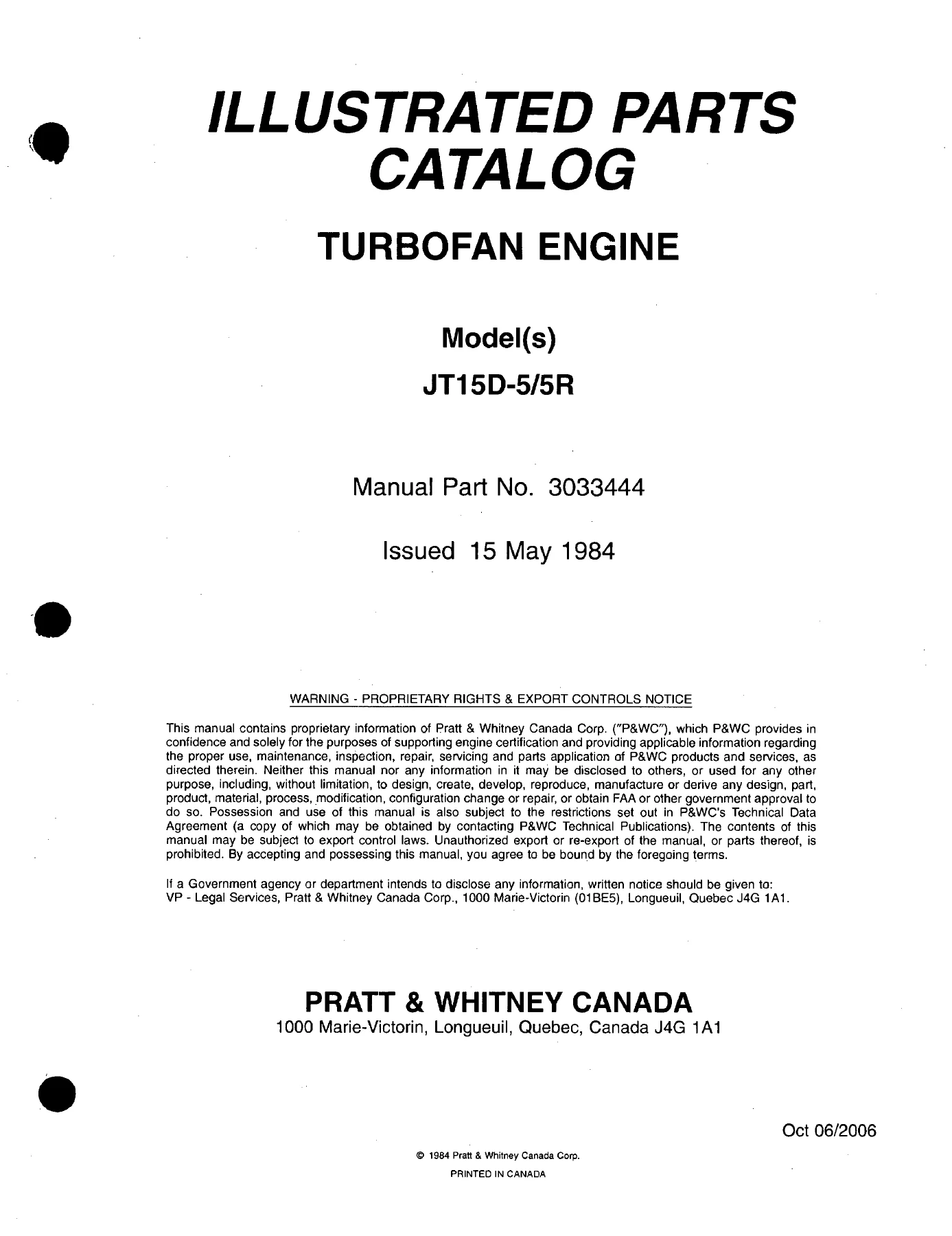
Pratt & Whitney Canada JT15D-5 JT15D-5R Turbofan Illustrated Parts Catalog 3033444
Original price was: $39.95.$23.95Current price is: $23.95.
P&WC Illustrated Parts Catalog for JT15D-5 and JT15D-5R twin-spool turbofan engines, Manual Part No. 3033444, Revision 31 dated Mar 09/2007. Lists assemblies, attaching hardware, interchangeability, and figure-keyed part numbers for requisitioning.
Description
Pratt & Whitney Canada JT15D-5 JT15D-5R Turbofan Illustrated Parts Catalog 3033444
This Pratt & Whitney Canada JT15D-5 JT15D-5R Turbofan Illustrated Parts Catalog 3033444 is the Illustrated Parts Catalog (IPC) used to identify, requisition, and issue the assemblies, subassemblies, and detail parts that support the JT15D-5 and JT15D-5R turbofan engines. Manual Part No. 3033444 was first issued 15 May 1984 and is carried here through Revision 31 dated 9 March 2007. The catalog is written as a supplement to the associated maintenance and overhaul manuals, which remain the final authority for work procedures. Baseline standards shown in the introduction are Engine Serial No. 100001 for the JT15D-5 and the allocated serial range beginning with PC-E100001 for the JT15D-5, with XXXXXX shown for the JT15D-5R.
File Details
- Manual type: Illustrated Parts Catalog (IPC)
- Brand / manufacturer: Pratt & Whitney Canada
- Models: JT15D-5 and JT15D-5R twin-spool turbofan
- Language: English
- Page count: 626
- File format: PDF
- Manual Part No.: 3033444
- Original issue: 15 May 1984
- Revision: 31 dated Mar 09/2007
- Prepared to ATA Specification No.: 100
What This Catalog Is For
The Pratt & Whitney Canada JT15D-5 JT15D-5R Turbofan Illustrated Parts Catalog 3033444 lists and illustrates the hardware that makes up a complete engine and its shipping container. Each Detailed Parts List uses six columns: Figure/Item, Part Number, Airline Part Number, Nomenclature, Effectivity Code, and Units per Assembly. Indentation in the nomenclature column shows the parent-to-child relationship from an assembly title down through attaching parts, details, subassemblies, and sub-subassemblies. Illustrations and list order follow a practical disassembly breakdown so a technician can walk from a complete engine figure into the compressor, combustor, turbine, gearbox, bypass duct, fuel, ignition, air, indicating, and oil sections.
The catalog is not a substitute for the Component Maintenance Manual or engine overhaul data. Where a bought-out accessory has its own supplier publication, Table 4 in the introduction points to the supplier code, supplier part number, P&WC part number, and ATA reference. That table covers bleed-valve actuators, ignition cables and exciters, oil coolers, electronic and hydromechanical fuel controls, the fuel/oil heat exchanger, fuel pumps, spark igniters, the flow divider valve, and the anti-icing solenoid valve.
Engine Models, Serial Range, and Build Specifications
JT15D is the basic prefix for the twin-spool turbofan family. The -5 and -5R suffixes are convenience designations used throughout this IPC. Effectivity on each parts-list page is marked A for JT15D-5 and B for JT15D-5R. Build Specification numbers further limit a part to a customer airframe installation:
- JT15D-5 BS 636 — Cessna (T-47A)
- JT15D-5 BS 657 and 713 — Raytheon (Beech Jet 400)
- JT15D-5 BS 1191 — Raytheon (Hawker 400XP)
- JT15D-5R BS 1220 — Raytheon (Beech Jet 400)
- JT15D-5R BS 1221 — Raytheon (Hawker 400XP)
IMAGES PREVIEW
When a Build Specification is not called out, the part is common to all installations listed for that model. Tables 1 and 2 in the introduction map those BS numbers to data plates, single ignition-exciter systems, magnetic chip detectors, motive-flow valves, oil filler and remote-panel hardware, on-line maintenance enhancement, and electrical wiring harnesses.
Chapters Covered
- Introduction — purpose, RSVP feedback, ATA Spec 100, engine identification, model designation, effectivity and build specification, revisions, service bulletins / spare parts bulletins / parts digests, detailed parts list rules, part numbering, item numbers, how to use the catalog, catalog terms and Part Replacement Codes, abbreviations, customer support, supplier codes, applicable documentation, nut options, part substitution list
- Numerical Index — Alpha Index and Numeric Index with chapter/section/subject, figure, item, and quantity
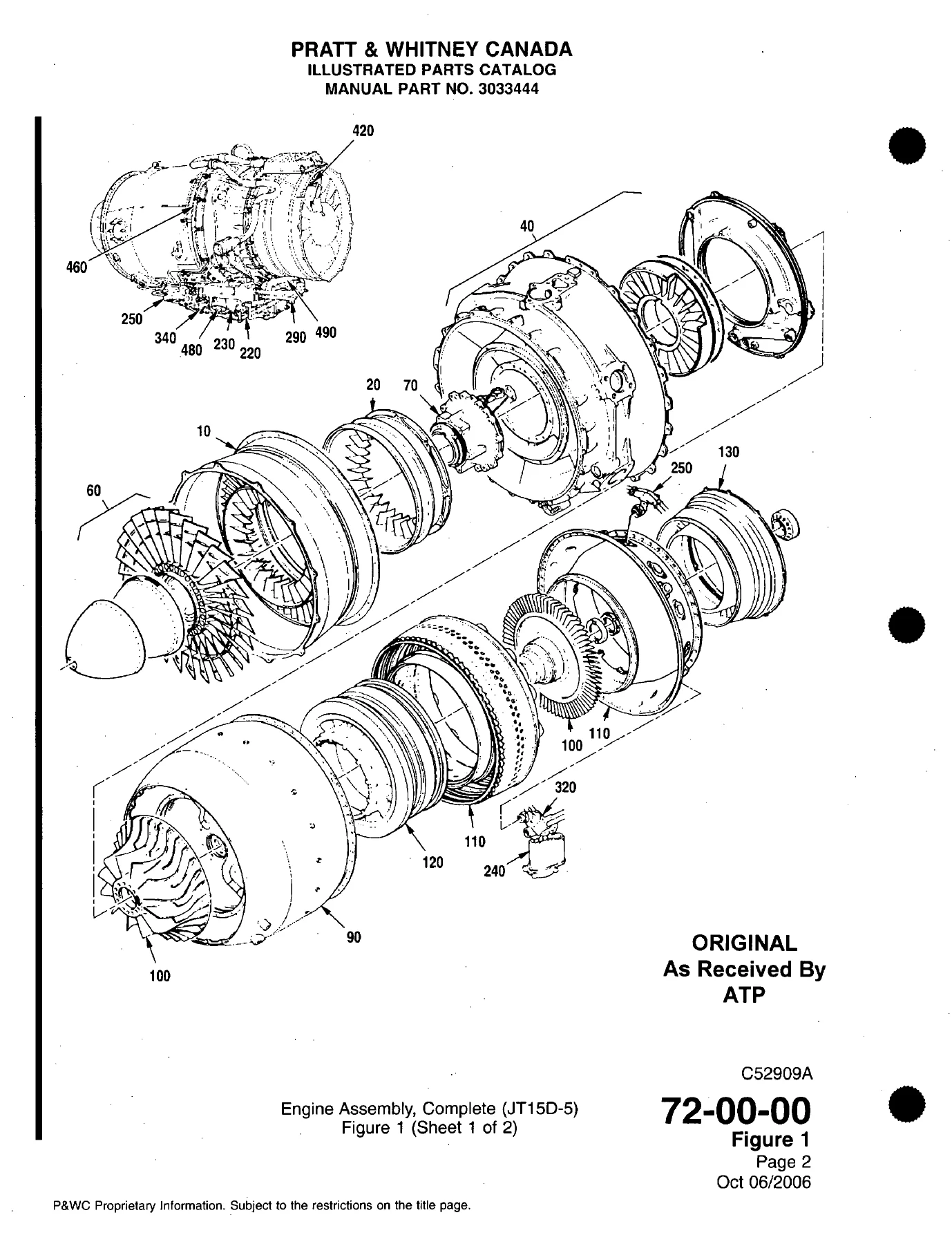
- 72-00 Engine, General — Engine Assembly, Complete (JT15D-5); Engine Assembly, Complete (JT15D-5R); Container Assembly, Complete Engine Shipping (JT15D-5 and JT15D-5R); Container Assembly, Engine Shipping; Skid Base Assembly, Container Shipping
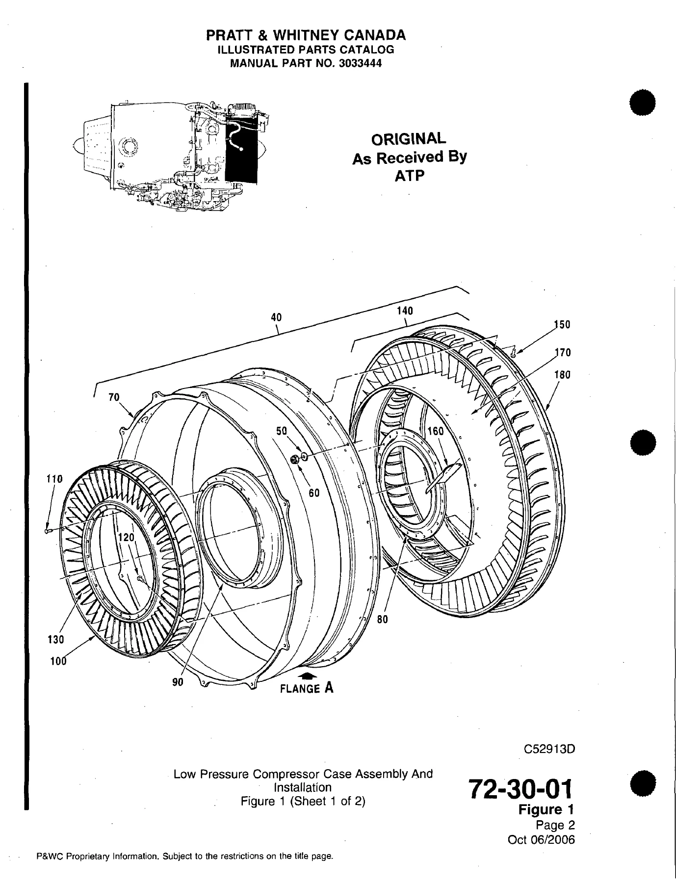
- 72-30 Compressor Section — Low Pressure Compressor Case Assembly and Installation; Low Pressure Compressor Stator Assembly and Installation; Intermediate Case, Intermediate Case Installation, and Case Assembly, Intermediate; Low Pressure Compressor Rotor Balancing Assembly Booster Stage; No. 1 Bearing Cover and Housing Installation; Gas Generator Case Installation; High Pressure Compressor Rotor Balancing Assembly; Compressor Bleed Valve Installation
- 72-40 Combustion Section — Combustion Chamber Liner and Low Pressure Turbine Stator Support Assembly
- 72-50 Turbine Section — High Pressure Turbine Stator, Large and Small Exit Ducts; High Pressure Turbine Disk Balancing Assembly; Low Pressure Turbine Rotor Balancing Assembly Installation; Second Stage Low Pressure Turbine Stator Assembly; Third Stage Low Pressure Turbine Stator Assembly; Exhaust Duct and No. 4 Bearing Housing Assembly
- 72-60 Accessory Gearbox and Drive — Accessory Gearbox and Drive Shaft Installation; Accessory Gearbox Assembly Externals, Internals, Oil Pump Assembly, Housing Assembly, and Cover Assembly
- 72-70 Bypass Section — Front Inner Bypass Duct Installation; Rear Inner Bypass Duct Assembly; Outer Bypass Duct Installation; Engine Rear Mount Installation
- 73-10 Engine Fuel and Control, Distribution — Fuel-to-Oil Cooler; Fuel Tube Installation (JT15D-5R); Fuel Pump (JT15D-5 and JT15D-5R); Fuel Pressure Tubes from Flow Divider Valve to Manifold; Flow Divider Valve; Fuel Manifold; Fuel Drain Lines for Combustion Chamber and Turbine Exhaust; Fuel Flowmeter; Fuel Pressure and Bypass Tubes; Pneumatic Tubes, Compressor Discharge Pressure; Emergency Fuel Shut-Off and Control Linkage; Bleed Valve Actuator; Fuel Filter (JT15D-5R); Fuel/Oil Heat Exchanger (JT15D-5R)
- 73-20 Controlling — Hydromechanical Fuel Control Unit; Electronic Fuel Control; Wiring Harness Installation Fuel Control (JT15D-5 and JT15D-5R); Rotors Speed and Temperature Sensor Installation
- 74-10 / 74-20 Ignition — Ignition Exciter and Mount; Ignition Cables and Attaching Hardware (JT15D-5 and JT15D-5R); Spark Igniters
- 75-00 Air — T1 Thermocouple Anti-Icing Air Tube (JT15D-5 and JT15D-5R); Low Pressure Compressor Anti-Icing Solenoid Valve and Tube; Cabin Air Bleed, Aircraft Services
- 77-00 Engine Indicating — T1 Thermocouple Wiring Harness (JT15D-5 and JT15D-5R); T6 Thermocouple Wiring Harness and Probes
- 79-20 / 79-21 Oil Distribution — Oil Filter Element, Housing and Pressure Relief Valve; Check Valves with Pressure and Bypass Oil Tubes; Pressure Oil Tubes including Anti-Siphon; Scavenge Oil Tubes
- 79-30 Oil Indicating — Oil Filler Neck and Plug; Remote Oil Indicator Panel; Oil Level Indicator and Tubes; Magnetic Chip Detector (JT15D-5 and JT15D-5R)
Taken together, those chapters give a shop the figure-keyed breakdown of a complete JT15D-5 or JT15D-5R powerplant from the low-pressure compressor case through the exhaust duct, plus the fuel, ignition, anti-ice, indicating, and oil hardware hung on the gas generator and accessory gearbox. Shipping-container and skid-base figures are included so a crate can be rebuilt or a spare engine can be identified as a complete assembly.
How the Numerical Index and Figures Work
When the part number is known, the Alpha or Numeric Index sends the user to the chapter/section/subject, figure, and item. The same item number appears on the exploded view and in the adjoining Detailed Parts List, which then shows nomenclature, attaching-parts grouping, units per assembly, and any PRE/POST Service Bulletin or Spare Parts Bulletin note. When the part number is not known, the user starts at 72-00-00 Figure 1 (Engine Assembly, Complete), picks the major group that contains the hardware, then reads the item number off the illustration. A dash in front of an item number means the item is listed but not drawn. Revised parts keep the same item number with a letter suffix A through Z.
Quantities in the Units per Assembly column are the quantity at that location, not always the engine total. AR and REF lines are excluded when totals are added. To obtain the quantity of one part for a full engine at a given Service Bulletin configuration, the user adds every item-number occurrence of that part number that belongs to the configuration.
Part Numbers, Interchangeability, and Bulletin Tracking
P&WC basic part numbers are seven-digit numbers in the 3000000 through 3099999 range and may carry letter or numeric suffixes that mark class, undersize, or oversize. A second series beginning 3100000-01 through -99 is used so the complete number can be quoted on procurement documents. Standard hardware uses an ST prefix. Supplier parts appear with the supplier number in the Part Number column and the P&WC equivalent in the Nomenclature column after the supplier code. Interchangeability Control (IC) / Option numbers must be used to order controlled interchangeable details; the shop does not order the individual detail numbers under an IC group. Part Replacement Codes used in the text include one-way interchangeable (PRC 01), two-way interchangeable (PRC 02), not interchangeable (PRC 03), interchangeable as a set (PRC 06), and restricted interchangeability (PRC 07). DELETED, TRANSFERRED, and N/A notations record removals and moves after bulletin activity.
The front-matter Service Bulletin List cross-references P&WC in-house numbers to ATA identifiers such as JT15D-72-7206 and records whether each bulletin was incorporated into the catalog or has no effect. The Spare Parts Bulletin List and the Parts Digest List (retained for history after Parts Digests were discontinued) sit in the same front section. Pre- and post-bulletin part numbers are written into the nomenclature column so a technician can see which configuration belongs on a given engine.
Supplier Codes and Related Component Manuals
Supplier codes printed in parentheses include K0642 Goodrich Actuation Systems, U1603 HS Marston Aerospace, 0AFL4 Champion Aerospace, 00198 Pratt & Whitney Canada, 02250 South Bend Controls, 12536 Ametek Hughes-Treitler, 15860 New Hampshire Ball Bearings, 59501 Unison Industries, 59875 Argo-Tech, 73030 Hamilton Sundstrand, and 99595 Goodrich Control Systems. Those codes matter when a fuel pump, igniter, cooler, or control unit is being purchased as a vendor item rather than as a P&WC-packaged assembly. Nut-option tables list IC part numbers such as ST3030-09, ST3030-10, ST3030-14, ST3066-11, 3012408, 3012414, 3012675, 3012680, 3015234, 3015598, 3016634, and 3026983 with the alternate nuts that may be supplied against each option.
Identify the Correct JT15D-5 or JT15D-5R Part Before You Order
The Pratt & Whitney Canada JT15D-5 JT15D-5R Turbofan Illustrated Parts Catalog 3033444 supports parts research, kit building, and configuration control on the compressor cases and rotors, intermediate and gas-generator cases, high- and low-pressure turbine disks and stators, accessory gearbox internals and oil pump, inner and outer bypass ducts, fuel pump and fuel control, ignition exciter and igniters, T1/T6 thermocouple harnesses, oil filter housing, and magnetic chip detector. Using the figure, item, effectivity letter, Build Specification, and PRE/POST bulletin notes together keeps the wrong class, the wrong airframe kit, or a superseded number off the purchase order. Maintenance and overhaul procedures still come from the companion manuals; this IPC is the illustrated list those procedures rely on when a part number has to be correct.
Download the PDF immediately after payment. There is no shipping wait. Open the file on a shop computer, tablet, or phone and print the figures or parts-list pages you need for a work package or a purchase request.
Reviews
There are no reviews yet.