
PTCUL Power Transmission Operation and Maintenance Manual – CBIP 2020 PDF
Original price was: $34.95.$21.95Current price is: $21.95.
PTCUL transmission operation and maintenance manual covering 400kV, 220kV and 132kV switchyard switching procedures, substation equipment maintenance, EHV line repair, protective relay indications, and CBIP-standard record formats.
Description
PTCUL Power Transmission Operation and Maintenance Manual – CBIP Edition
This is the revised and updated PTCUL Power Transmission Operation and Maintenance Manual prepared by the Power Transmission Corporation of Uttarakhand Limited and edited by the Central Board of Irrigation & Power (CBIP), New Delhi. It is the working reference for engineers and technicians who operate and maintain the high-voltage transmission system that carries power across Uttarakhand, covering decade-old lines and substations in both plain and hilly terrain as well as newer additions to the state grid.
The manual is arranged in two technical sections. Section I — Operation Handbook lays out step-by-step switching procedures for 400kV, 220kV and 132kV switchyards. Section II — Maintenance Manual sets out preventive maintenance procedures, technical requirements, line maintenance, and the standard registers and formats that each substation and transmission line office is expected to maintain.
File Details
- Manual type: Operation & Maintenance Manual (transmission utility document)
- Issuing utility: Power Transmission Corporation of Uttarakhand Limited (PTCUL)
- Edited by: Central Board of Irrigation & Power (CBIP), Malcha Marg, Chanakyapuri, New Delhi
- Language: English
- File format: PDF
- Publication date: July 2020
- Coverage: 400kV, 220kV and 132kV switchyards; EHV transmission lines up to 400kV AC; substation equipment and protective relays
Chapters Covered
- Section I — Operation
- Operational Procedures for 400kV switchyard — line isolation, restoration, fault tripping restoration, switching off under high voltage, transformer bay isolation and restoration, bus reactor isolation and restoration, bus shutdown and restoration, busbar protection restoration, transfer bus coupler (TBC) load transfer both ways
- Operational Procedures for 220kV switchyard — line isolation, restoration and fault restoration, transformer bay isolation and restoration, bus transfer and restoration, busbar protection relay restoration, TBC load transfer
- Operational Procedures for 132kV switchyard — line isolation, restoration and fault restoration, transformer bay isolation and restoration, single bus isolation and restoration
- Sample list of relay indications — distance protection schemes (MM3V, Quadra Mho, Micro Mho, Optimho, EPAC, RAZFE, REL 100, THR), numerical distance and differential relay LED tables
- Daily checks
- Section II — Maintenance Manual
- Regulatory and statutory guidelines for O&M of the transmission system
- Important provisions of the State Grid Code
- Preventive maintenance procedures for all substation equipment
- General technical requirements for main and auxiliary substation equipment
- Gas Insulated Switchgear (GIS) substation
- Substation automation
- Maintenance procedures of EHV transmission lines
- Important parameters and data used in transmission lines
- Probable causes of failure of transmission line components
- Essential registers to be maintained at each substation
- Record formats for EHV substations and EHV lines
- Standard acceptable technical values and references
- Acronyms and abbreviations
Taken together, the PTCUL Power Transmission Operation and Maintenance Manual gives a field technician the full switching logic for every common bay configuration on the state grid, the maintenance checklist and interval for each item of switchyard plant, and the reference values needed to judge whether a reading is acceptable or a defect must be raised. Section I is procedural — it tells you the exact order in which breakers, isolators and earth switches are operated, when the opposite end must be consulted, when LDC or SLDC clearance is required, and how line clear permits are issued and returned. Section II is diagnostic and prescriptive — transformer and reactor supervision, breather and conservator checks, Buchholz and gas pressure relay testing, OLTC inspection, dissolved gas analysis interpretation, circuit breaker SF6 and operating mechanism checks, instrument transformer maintenance, disconnector and earth switch servicing, surge arrester leakage monitoring, battery and charger maintenance, DG set, air conditioning, fire fighting and switchyard general maintenance.
Switching and Restoration Procedures for Every Bay Type
The operation section is not a set of general principles — it is a written sequence for each job. For 400kV lines there are separate procedures for isolation for maintenance work, restoration after maintenance, restoration after fault tripping, and switching off the line due to high voltage under LDC instruction. The same pattern repeats for 400kV ICT bays, 400kV bus reactor bays, 400kV main bus shutdown and restoration, and 400kV busbar scheme restoration after busbar protection operation. The transfer bus coupler procedures are written out in both directions — transferring load from main bus to transfer bus and back from transfer bus to main bus — with the CT switching relay and PT selection relay operations that must be confirmed at each step.
The 220kV and 132kV sections follow the same discipline. The 220kV procedures include isolation of one main bus by transferring load to the other, restoration of a main bus, restoration after 220kV busbar protection relay operation, and TBC load transfer. The 132kV section adds the single bus isolation and restoration procedure, which is laid out in the order the CBs of the transformer bay and each connected 132kV line must be taken out, the PT isolator opened and bus voltage confirmed at zero, and earthing applied at either end before the line clear permit is issued.
Throughout, the manual enforces the practical safety rules of a live EHV switchyard: hand gloves for local isolator and earth switch operation, physical verification in the yard that all three poles have actually operated, confirmation of lamp, semaphore and SCADA schematic indications, resetting of CT switching and PT selection relays, cordoning the isolated bay with manila rope, and hanging the LCP ISSUED & MEN AT WORK board on the control panel.
Relay Indications and Numerical Relay Reference
A dedicated chapter lists relay indications for the older static and electromechanical distance protection schemes still in service — the MM3V flag description set, the Quadra Mho, Micro Mho, Optimho and EPAC LED sets, and the RAZFE, REL 100 and THR flag descriptions. Each entry maps the flag or LED to the phase fault, ground fault or zone that it represents, including carrier send, carrier received, auto-reclose lockout, switch-on-to-fault, power swing and VT fuse fail indications.
For numerical relays the manual provides structured tables for distance protection relays on lines and differential protection relays on transformers, with each function, whether an LED is provided, and whether the indication is latching or non-latching. Functions include phase and neutral trips, Z1 to Z4 distance zones, carrier aided trip, power swing block and trip, VT fuse fail and VT MCB trip, aided and backup directional earth fault trip, carrier channel fail, broken conductor trip, over voltage alarm and trip on the line relay; and on the transformer differential relay, the phase and neutral trips, Idiff> trip, diff unrestrained trip, second and fifth harmonic block, main tank Buchholz and PRV trip, OLTC Buchholz and PRV trip, winding and oil temperature high trip, HV and LV REF trip, and directional phase and earth overcurrent trip.
Substation Equipment Maintenance Procedures
Section II works through each item of plant in turn, with the specific checks a maintenance crew is expected to perform. For transformers and reactors this includes dirt and dust inspection, rust treatment, mechanical damage checks, joint leakage checks using liquid chalk to locate a leak, oil level checks on conservator and bushings, silica gel breather condition and reactivation temperature, drycol breather operation, conservator oil level checks against top oil temperature, air cell leakage testing, marshalling kiosk inspection, cooling system fan and pump checks, OTI and WTI calibration, gas pressure relay and Buchholz relay testing, bushing cleaning and grading, and OLTC inspection and maintenance including hand and electrical operation, drive motor overload setting, out of step relay checking, tap change incomplete alarm, and remote indication checking.
Dissolved Gas Analysis is covered in depth — the fault gases (hydrogen, methane, ethane, ethylene, acetylene, carbon monoxide, carbon dioxide, nitrogen and oxygen), individual fault gas acceptable limits by transformer type, total dissolved combustible gas limits with action bands, gas evolution temperature relationships, and the faults associated with different gases including oil overheating, overheated cellulose, partial discharge in oil and arcing in oil.
Circuit breaker maintenance is laid out as a checklist with the interval for each point — half yearly porcelain cleaning and visual inspection, yearly SF6 gas pressure and low gas pressure alarm and lockout circuit checks, dew point measurement, air pressure setting checks, capacitance and tan delta measurement for grading capacitors, insulation resistance, PIR resistance, contact resistance, dynamic contact resistance, operation timing, contact travel, pole discrepancy relay checking, auxiliary control circuit checking, and operating mechanism lubrication. SF6 gas handling and the evacuation level before refilling are also described.
Instrument transformers, capacitor voltage transformers and coupling capacitors each get their own checklist — oil level and leakage, secondary terminal tightness, tan delta test tap earthing, DGA and BDV of oil when tan delta or IR is poor, nitrogen pressure where applicable, gasket and vermin proofing, and earthing of structures and secondary connection boxes. Disconnectors and earth switches, surge arresters, batteries and battery chargers, distribution transformers, LT AC distribution boards, air conditioning plant, air compressors, fire fighting systems including hydrant, HVW spray and mulsifire systems, and DG sets all have dedicated checklists with periodicities.
Protection System Testing
The protection chapter gives test schedules for distance protection, common tests for distance and unit protections, busbar protection, differential relays, under voltage relays, over voltage relays, neutral displacement relays, overcurrent and earth fault relays, under frequency relays, over fluxing relays, local breaker backup, restricted earth fault, and fuse failure relays. It also covers the maintenance of numerical relays (IEDs) and the corrective action to take when a relay shows no run indication, no display, incorrect tripping, or mismatched binary input and output configuration — with the guidance to call the T&C engineer rather than disturb relay settings or formatting on site.
Transmission Line Maintenance and Repair
The EHV line maintenance procedures cover the activities carried out after a line is declared faulty — locating the fault, patrolling and scheduling restoration, and the practical site work: clearing approach and site, forming sub gangs, arranging transport, first aid and potable water, and site camping. General safety precautions for working on a de-energized circuit of a twin or quad bundle line are set out in detail, with the definitions used by the safety rules (earth end clamp, line end clamp, earth lead, earthing pole, pole extension, trailing earth, bridging pole, bridging earth, working phases, field equipment earth), the dangers of the job, and the precautions before climbing or working on towers or conductors — green flags at anti-climbing device and cross-arm level on the shutdown circuit side, six red flags on the centre line at cross-arm level to mark the live circuit danger zone, and the correct sequence of connecting and removing additional earths.
Repair procedures are given for tower collapse and foundation failure, cross-arm failure, earth wire failure at dead end, near suspension clamp and within span, jumper failure, conductor snapping and breakage, insulator failure, and hardware failure. Step-by-step methods are written for replacement of outer suspension insulator strings and tension insulator strings, catching off and holding twin and quad conductors at suspension towers, repairing twin conductor at ground on 400kV tension towers and suspension towers, and compression jointing of conductors using the steel sleeve and aluminium sleeve with hot paste filler injection. Manpower and time estimates are given for each activity, and the T&P generally required is tabulated for each job.
Tree cutting and trimming has its own chapter covering the reasons for tree cutting during construction and maintenance, the effect of tree branches entering the clearance zone, and the use of leaf discolouration and dehydration as a patrolling indicator that branches are too close. Tower foundation problems including land slide, hill sinking and soil erosion, along with protection measures such as cement slurry injection, crate work, retaining walls and soil compaction, are also addressed.
Parameters, Data and Standard Values
The parameters chapter collects the working data a line engineer needs — wind zones and basic wind speeds, maximum conductor and earth wire temperatures, normal design spans by voltage class, wind span and weight span, permissible weight span tables for 400kV, 220kV, 132kV and 66kV lines in plain and hilly terrain, current carrying capacity of standard ACSR conductors, EHV line loadability by line length, thermal rating of Moose, Zebra and Panther conductors, and air clearances including minimum ground clearance, clearance above rivers and lakes, mid span clearance between conductor and earth wire, clearances at power line crossings, clearances over railway tracks, and clearances to ground, buildings and roads under the IE Rules.
Insulator string configurations by voltage class, right of way corridor requirements, and important mechanical data for conductors from Dog through Panther, Zebra, Moose, Bersimis and Curlew are tabulated, along with data for normal earth wire, special earth wire and OPGW. The probable causes of failure chapter works through insulators and hardware fittings, conductor and conductor accessories, earth wire and earth wire accessories, towers, nuts and bolts, tower foundations, and earthing electrodes and strips — including the adverse effects of vibration on conductor, earth wire, armour rods, clamps, tower members, insulators, arcing horns, jumpers and earth wire flexible bonds.
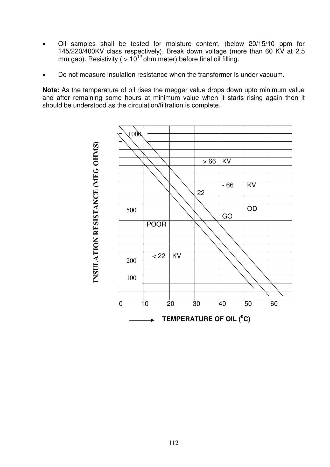
Standard acceptable technical values are collected at the back of the manual as reference tables: fresh transformer oil before filling and in-service transformer oil parameters with source standards, dissolved gas analysis typical rates of gas increase, transformer and reactor tan delta and capacitance values, insulation resistance values, polarization index interpretation bands, winding resistance, voltage ratio, sweep frequency response analysis interpretation, moisture measurement of winding with degree of polymerization life estimates, circuit breaker operating timings for 400kV, 220kV and 132kV, travel of operating rod by make, PIR times by make, grading capacitor capacitance and tan delta, contact resistance, evacuation level, IR values, pressure switch settings, current transformer IR and tan delta with monitoring action bands, CVT tan delta and capacitance drift action bands, disconnecting switch contact resistance, surge arrester third harmonic resistive current action bands, station earth resistance, battery specific gravity, and DG set winding IR value.
Registers, Formats and Grid Code Provisions
The manual lists the essential registers to be maintained at each substation — index register, plant history register, shift arrangement register, attendance register, testing register, defect register, daily energy account register, shutdown form register, tripping register for the primary system, stoppage register, authorization register, instruction register, inspection register, rostering register, message register (control and local), maximum and minimum load register, sealing register, monthly energy account register, carrier fault register, compressor reading register, LA surge counter reading register, and daily log sheet. Blank formats are supplied for each.
Record formats for EHV substations and EHV lines are provided as fill-in sheets — shutdown maintenance activity sheets for scheduled planned and unscheduled forced work, monthly and yearly transformer and reactor maintenance records, tan delta measurement for bushings, circuit breaker monthly maintenance, current transformer monthly and yearly maintenance with thermovision scanning, capacitor voltage transformer maintenance, disconnecting switch and earth switch maintenance, surge arrester maintenance, busbar and bus post insulator maintenance, wave trap maintenance, substation illumination maintenance, air conditioning system maintenance, battery set maintenance, fire fighting system maintenance, fire alarm system maintenance, DG set maintenance, PLCC equipment maintenance, and preventive maintenance records for protection systems. Line-side formats cover the maintenance schedules of transmission lines, ground patrolling checklists, monthly patrolling programme, summary of line defects, log book of line defects, tower climbing patrolling report, line declared faulty inspection report, inspection report for major maintenance and breakdown works, and live line puncture insulator detection.
The regulatory chapter reproduces the availability and incentive provisions that apply to the transmission licensee — target availability for recovery of full transmission charges, the incentive formula, the circumstances in which an element is deemed available despite an outage, the contingencies excluded from outage time, and the provisions relating to deemed outage periods. The State Grid Code chapter covers safety standards, fault clearance time requirements for 400kV and for 220kV and 132kV, the operating policy, system security aspects, the permissible voltage operating range at 400kV, 220kV, 132kV and 66kV, demarcation of responsibilities for special energy meters, and reactive power and voltage control through 400kV bus and line reactor switching and ICT tap changing on SLDC instruction.
What This Manual Enables You to Do
With this PTCUL Power Transmission Operation and Maintenance Manual in front of you, a switchyard operator can walk through a 400kV, 220kV or 132kV isolation, a restoration after maintenance, a restoration after fault tripping, a bus transfer through the transfer bus coupler, a main bus shutdown, or a busbar protection restoration — in the correct sequence, with the correct confirmations at each step, and with the correct entries in the LCP book and registers. A maintenance engineer can plan a preventive maintenance shutdown from the checklists, know which items are half yearly, yearly, two yearly or as-required, and record the work on the supplied formats. A protection engineer can interpret a relay facia on an old static scheme or a numerical distance or differential relay, decide whether a test charge is permissible or whether the equipment must be tested first, and follow the correct fault analysis sequence. A line engineer can plan and execute a tower collapse restoration, a conductor repair on a 400kV twin conductor, an insulator string replacement, or an earth wire repair, with the T&P list, manpower estimate and safety sequence for each job.
The value of a document like this is that it removes guesswork from high-voltage work. The switching order matters because an isolator operated in the wrong sequence while current is flowing can fail catastrophically. The earthing sequence matters because an additional earth connected in the wrong order exposes a lineman to induced voltage. The relay indication matters because a transformer tripped on Buchholz or differential protection must not be test charged before investigation, while a transformer tripped on a backup relay due to a reflected downstream fault may be test charged with SLDC permission. Having the written procedure and the standard acceptable values in one place is what allows those decisions to be made correctly and consistently, shift after shift.
IMAGES PREVIEW
Delivery is instant. After payment the PDF is available for immediate download — no shipping, no waiting for a printed copy to arrive. It can be opened on any device that reads PDF, and individual checklists, record formats and reference tables can be printed for use at the substation, in the control room or on site.
Reviews
There are no reviews yet.