Puritan Bennett 700 Series Ventilator Service Manual PDF
Original price was: $110.00.$30.95Current price is: $30.95.
Acquire the official Puritan Bennett 700 series ventilator service manual PDF for models 740 and 760, detailing safety guidelines, theory of operation, self-tests, diagnostic codes, alarm messages, performance verification, and repair procedures. This Nellcor Puritan Bennett 740 repair guide includes pneumatic/electrical systems overviews, troubleshooting, parts lists with alphabetic/numeric indexes, and preventive maintenance kits for ventilator breathing circuits and accessories. Vital Puritan Bennett 760 ventilator troubleshooting manual for biomedical technicians.
Description
Puritan Bennett 700 Series Ventilator Service Manual PDF DOWNLOAD
Description
The Puritan Bennett 700 series ventilator service manual PDF is a thorough technical reference for servicing Nellcor Puritan Bennett 740 and 760 ventilator systems, emphasizing safety, diagnostics, and maintenance to ensure reliable life-support operation. Published in November 1999 by Nellcor Puritan Bennett (with Mallinckrodt distribution), it provides in-depth coverage of ventilator configurations, electromagnetic susceptibility, and warranty details, warning against unauthorized modifications that could endanger patients or operators. As an essential Nellcor Puritan Bennett 740 repair guide, it outlines tools, equipment, service materials, periodic maintenance schedules, and controls/indicators for efficient repairs. This Puritan Bennett 760 ventilator troubleshooting manual integrates practical instructions for self-tests (POST, SST, EST), service/utility functions like sensor data review and calibrations, performance verification using RT-200 or PTS 2000 analyzers, alarm classifications, and diagnostic codes for software/hardware issues.
The table of contents is extracted from pages xi to xvi and categorized below using bullet points for clarity. No bookmarks are present in the document, but an alphabetical and numerical parts index follows the parts list in Section 9, aiding in component location. A comprehensive index at the manual’s end (starting around page 457) lists topics like removing/installing components, NVRAM contents, and torque specifications, formatted alphabetically for quick reference. The remaining pages feature diagrams, wiring schematics, and step-by-step procedures, making it a critical Puritan Bennett ventilator parts index manual and Puritan Bennett ventilator maintenance kit guide for tasks such as piston/cylinder disassembly, oxygen regulator adjustments, and exhalation system repairs.
Categorized Table of Contents:
- General Information
- How to use this manual: 1-1
- Safety: 1-1
- General description: 1-2
- Configuration information: 1-4
- Accessories: 1-4
- Specifications: 1-4
- Tools, Equipment, and Service Materials: 1-9
- Periodic maintenance: 1-14
- Service kits: 1-15
- Controls and indicators: 1-15
- VENTILATOR SETTINGS: 1-18
- PATIENT DATA: 1-24
- VENTILATOR STATUS: 1-29
- Location of ventilator serial number: 1-30
- Determining software revision: 1-30
- Service philosophy: 1-30
- Reference documentation: 1-30
- Theory of Operation
- Overview of ventilator operation: 2-1
- Pneumatic system: 2-2
- Gas Inlet System Overview: 2-6
- Piston/cylinder system: 2-13
- Inspiration manifold system: 2-20
- Patient system: 2-24
- Exhalation system: 2-27
- PEEP/CPAP system: 2-31
- Electrical system: 2-34
- Power assembly: 2-38
- Internal battery: 2-45
- External battery: 2-46
- Pressure solenoid PCB: 2-47
- Controller PCB: 2-50
- User interface (UI): 2-54
- Miscellaneous electronic parts: 2-58
- Communications option: 2-61
- Motor control and drive: 2-61
- Breath delivery: 2-62
- Piston initialization: 2-65
- Breath triggering: 2-66
- Gas delivery to the patient: 2-68
- Exhalation and piston retraction: 2-70
- Power source switchover: 2-76
- Emergency modes: 2-78
- Occlusion cycling mode: 2-78
- Ventilator inoperative: 2-79
- Safety valve open (SVO): 2-80
- Self-Tests
- Introduction: 3-1
- Power-on self-test (POST): 3-2
- Structure of POST: 3-2
- Running POST: 3-2
- How the ventilator responds to a POST error: 3-2
- Short self-test (SST): 3-6
- Extended self-test (EST): 3-6
- When to run: 3-6
- Hardware requirements: 3-7
- Running EST: 3-7
- Troubleshooting: 3-17
- Ongoing checks: 3-23
- Service and Utility Functions
- Introduction: 4-1
- Accessing the service or utilities functions: 4-1
- Summary of functions: 4-2
- Navigating the Service and Utilities menus: 4-2
- About the test and alert logs and EST test results: 4-4
- Service functions: 4-4
- Sensor data: 4-4
- EST (Extended self-test): 4-8
- Diagnostics/Calib: 4-8
- Review alert log: Reading the alert log: 4-26
- Test data: Reading the test log or EST test results: 4-26
- Utilities functions: 4-27
- Pressure format: 4-27
- Date and time format: 4-27
- Introduction: 4-1
- Performance Verification
- When to run: 5-1
- Tools, test equipment, and service materials: 5-2
- Preliminary ventilator cleaning and inspection: 5-3
- Preliminary ventilator setup: 5-4
- Preliminary pneumatic test equipment setup: 5-4
- Performance verification procedures: 5-4
- Electrical safety test and power-on self-test (POST) (Test 1): 5-5
- Rotary encoder test (Test 2): 5-6
- Battery test (Test 3): 5-6
- Supply voltage test (Test 4): 5-8
- Gas volume accuracy, breath timing, and PEEP system test (Test 5), using the RT-200 Pneumatic Calibration Analyzer: 5-9
- Gas volume accuracy, breath timing, and PEEP system test (Test 5), using the PTS 2000 and Breathlab software: 5-13
- Extended self-test (EST) (Test 6): 5-17
- Oxygen accuracy test (Test 7) using the RT-200: 5-17
- Oxygen accuracy test (Test 7) using the PTS 2000: 5-21
- High pressure alarm test (Test 8) using the RT-200: 5-24
- High pressure alarm test (Test 8) using the PTS 2000: 5-25
- Safety valve test (Test 9): 5-26
- Troubleshooting: 5-27
- Diagnostic Codes
- How to use this section: 6-1
- About software errors: 6-1
- About ventilator status (13000 series) codes: 6-2
- List of codes: 6-2
- Alarm Messages
- Alarm classifications: 7-1
- Responding to alarms: 7-1
- Service and Repair
- Introduction: 8-1
- How to use this section: 8-1
- General repair safety: 8-1
- General repair guidelines: 8-2
- Repair-related cleaning: 8-3
- Electrical cables and pneumatic tubing: 8-3
- Adhesive use: 8-3
- Electrostatic discharge control: 8-4
- Repainting and touch-up: 8-5
- Replacement part ordering: 8-5
- Post-repair: 8-5
- Patient system and accessories: 8-5
- Cart assembly: 8-6
- Removing/installing ventilator from/to cart: 8-6
- Removing/installing oxygen cylinder brackets: 8-8
- Removing/installing cylinder covers: 8-9
- Removing/installing collector vial support bracket: 8-9
- Removing/installing humidifier support bracket: 8-9
- Removing/installing basket: 8-9
- Removing/installing external battery and cover: 8-11
- Shelf mount: 8-12
- Removing/installing ventilator from/to shelf mount: 8-12
- Removing/installing collector vial support bracket: 8-13
- Removing/installing humidifier support bracket: 8-13
- User interface (UI) assembly (lid): 8-14
- Opening and propping lid: 8-14
- Removing/installing lid: 8-14
- Knob and rotary encoder: 8-16
- UI display PCB: 8-17
- LCD panel (message window): 8-18
- Keyboard assembly: 8-19
- Ventilator head cabinet assembly: 8-20
- Oxygen adapter assembly: 8-20
- Options panel plate: 8-21
- Communications option: 8-22
- Air intake cover and filter: 8-27
- Air flow thermistor assembly: 8-28
- Oxygen fitting, inspiration access panel, and air intake manifold assembly: 8-28
- Air intake filter switch: 8-30
- Flex arm mounting block: 8-31
- Removing/installing cabinet assembly: 8-31
- Oxygen regulator, oxygen solenoid, mixing manifold, and cylinder inlet check valve: 8-32
- Removing oxygen regulator, oxygen solenoid, mixing manifold, and cylinder inlet check valve: 8-33
- Installing oxygen regulator, oxygen solenoid assembly, mixing manifold, and cylinder inlet check valve: 8-36
- Oxygen regulator pressure transducer: 8-37
- Inspiration manifold assembly: 8-38
- Oxygen sensor: 8-38
- Inspiration manifold thermistor: 8-40
- Safety valve assembly: 8-40
- Removing/installing inspiration manifold assembly: 8-41
- Exhalation assembly: 8-43
- Exhalation assembly cover: 8-43
- Exhalation heater and thermistor assemblies: 8-44
- Exhalation assembly: 8-46
- Exhalation check valve: 8-47
- Exhalation valve: 8-48
- Exhalation flow sensor assembly: 8-48
- Cable management bar, PCBs, speaker, and piezo alarm: 8-49
- Speaker: 8-49
- Piezo alarm: 8-50
- Pressure solenoid PCB and controller PCB: 8-50
- Cylinder and exhalation pressure transducer autozero solenoids: 8-57
- Cable management bar: 8-57
- PEEP pump and reservoir: 8-58
- PEEP pump: 8-58
- PEEP reservoir and filter: 8-58
- Exhalation solenoid: 8-59
- Piston/cylinder and motor/encoder assemblies: 8-60
- Optoswitches: 8-60
- Removing/installing piston/cylinder and motor/encoder assemblies: 8-60
- Greasing rack: 8-62
- Meshing motor pinion gear with rack: 8-62
- Ventilator rear components: 8-67
- Main fan and filter: 8-67
- Internal battery: 8-67
- Power assembly: 8-69
- Power cord: 8-69
- Removing power assembly: 8-69
- Line filter: 8-70
- Circuit breaker: 8-71
- Power switch: 8-71
- External battery harness: 8-72
- Power supply: 8-73
- Power supply fan: 8-76
- BBU PCB and heatsink bars: 8-77
- Harnesses and wiring: 8-78
- Main ventilator head harness: 8-78
- Introduction: 8-1
- Parts List
- How to use this parts list: 9-1
- 700 Series Ventilator System patient system and accessories parts list: 9-3
- Oxygen hose assemblies: 9-7
- Flex arm assembly: 9-8
- Ventilator major assemblies: 9-9
- Cart assembly: 9-12
- Shelf mounting kit: 9-18
- User interface (UI) assembly: 9-20
- Ventilator head assembly: 9-23
- Oxygen hose adapters: 9-30
- Label kit: 9-32
- Inspiration manifold assembly: 9-34
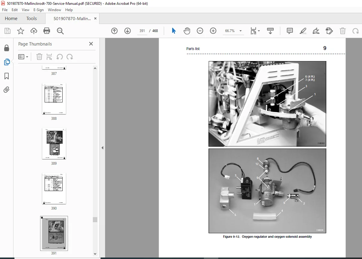
- Oxygen regulator and oxygen solenoid assembly: 9-36
- Exhalation assembly: 9-38
- Cable management bar, PCBs, speaker, and piezo alarm: 9-41
- PEEP pump and reservoir: 9-46
- Piston/cylinder and motor/encoder assemblies: 9-48
- Ventilator rear components: 9-52
- Power assembly: 9-54
- Power cords: 9-60
- Tubing: 9-62
- Harnesses and wiring: 9-64
- 15,000-hour preventive maintenance kit: 9-67
- 30,000-hour preventive maintenance kit: 9-68
- 700 Series Ventilator spare parts kit: 9-69
- Service tool kit: 9-71
- Oxygen sensor assemblies: 9-72
- Communications option: 9-72
- 760 Ventilator assemblies: 9-72
This Puritan Bennett ventilator parts index manual and Puritan Bennett ventilator maintenance kit guide support real-world biomedical applications, including EST troubleshooting and component replacements, while adhering to IEC standards for electromagnetic compatibility.
File Details
- Manual Name: 700 Series Ventilator System Service Manual
- Models Covered: 740, 760
- Year: 1999
- Manual PDF Quality: High (professional formatting, diagrams, and clear text)
- No of Pages: 468