RAYMOND 31 EASI 2 REACH PARTS CATALOG MANUAL – PDF DOWNLOAD
$25.95
RAYMOND 31 EASI 2 REACH PARTS CATALOG MANUAL – PDF DOWNLOAD
Description
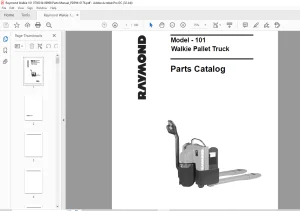
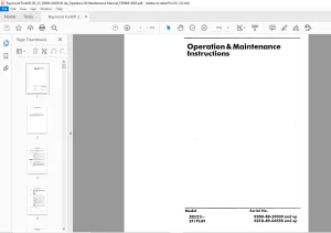
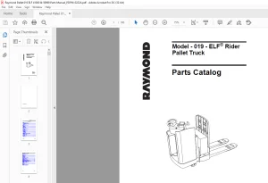
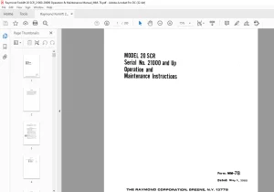
RAYMOND 31 EASI 2 REACH PARTS CATALOG MANUAL – PDF DOWNLOAD
FILE DETAILS:
RAYMOND 31 EASI 2 REACH PARTS CATALOG MANUAL – PDF DOWNLOAD
Language : English
Pages :147
Downloadable : Yes
File Type : PDF
Size: 238
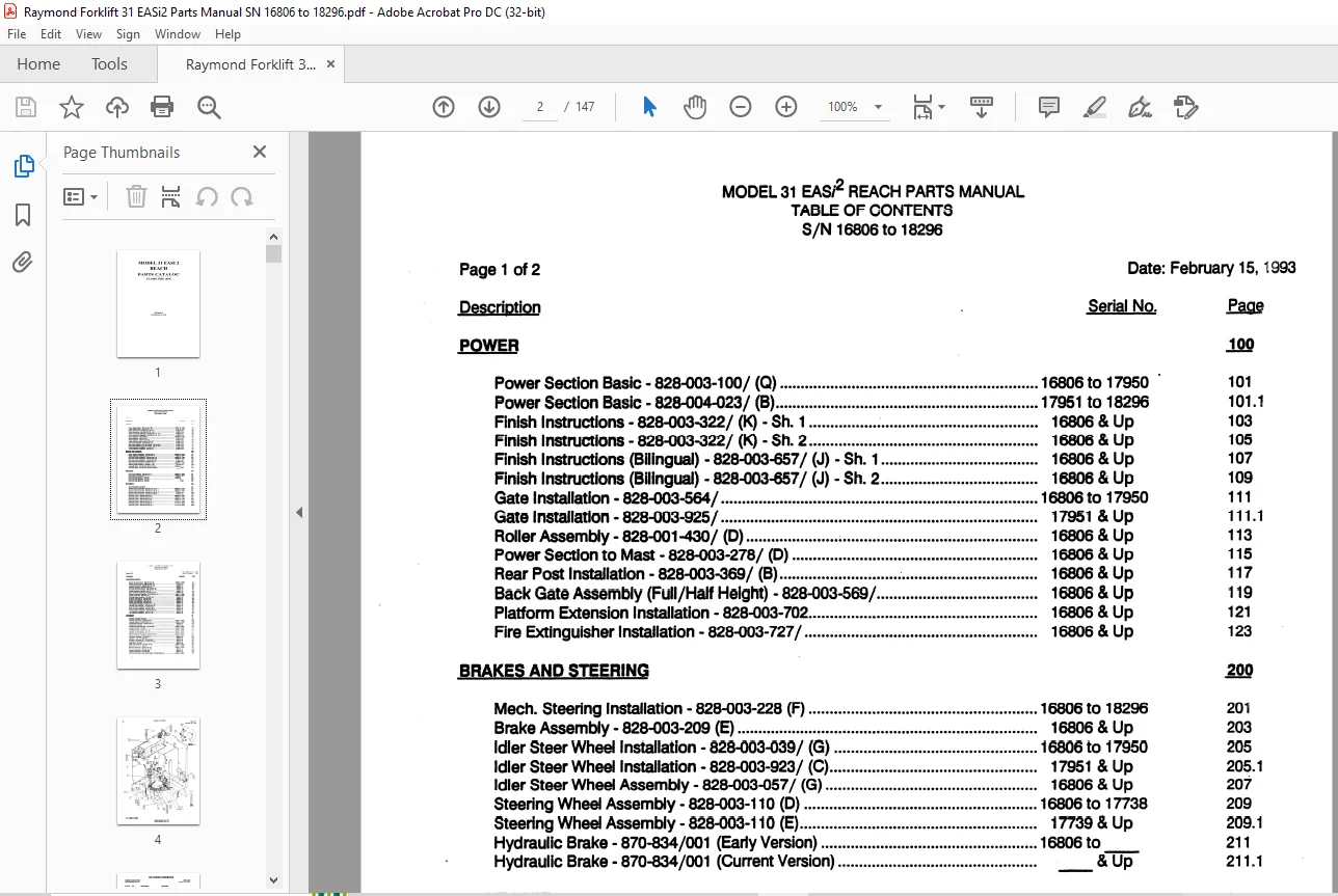
TABLE OF CONTENTS:
RAYMOND 31 EASI 2 REACH PARTS CATALOG MANUAL – PDF DOWNLOAD
Power Section Basic-828-003-100/ (Q) 16806 to 17950 101
Power Section Basic – 828-004-023/ (8) 17951 to 18296 1011
Finish Instructions -828-003-322/ (K) -Sh 1 16806 & Up 103
Finish lnstructlons-828-003-322/ (K) – Sh 2 16806 & Up 105
Finish Instructions (BIiinguai) – 828-003-657 / (J) – Sh 1 16806 & Up 107
Finish Instructions (BIiinguai) – 828-003-657 / (J) – Sh 2 16806 & Up 109
Gate Installation – 828-003-564/ 16806 to 17950 111
Gate Installation – 828-003-925/ 17951 & Up 1111
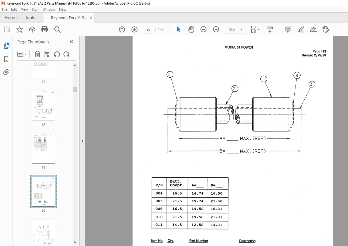
Roller Assembly-828-001-430/ (D) 16806 & Up 113
Power Section to Mast -828-003-278/ (D) 16806 & Up 115
Rear Post Installation -828-003-369/ (B) ~ 16806 & Up 117
Back Gate Assembly (Full/Half Height) -828-003-569/ 16806 & Up 119
Platform Extension Installation -828-003-702 16806 & Up 121
Fire Extinguisher Installation -828-003-727 / 16806 & Up 123
BRAKES AND STEERING 200
Mech Steering Installation -828-003-228 (F) 16806 to 18296 201
Brake Assembly – 828-003-209 (E) 16806 & Up 203
Idler Steer Wheel Installation – 828-003-039 / (G) 16806 to 17950 205
Idler Steer Wheel Installation -828-003-923/ (C) 17951 & Up 2051
Idler Steer Wheel Assembly – 828-003-057 / (G) 16806 & Up 207
Steering Wheel Assembly – 828-003-11 o (D) 16806 to 1 n38 209
Steering Wheel Assembly – 828-003-11 o (E) 1 n39 & Up 2091
Hydraulic Brake -870-834/001 (Early Version) 16806 to_ 211
Hydraulic Brake -870-834/001 (Current Version) & Up 2111
DRIVE UNIT 300
Drive Unit Installation – 828-003-181 (L) 16806 to 18296 301
Drive Motor-570-262/500 16806 & Up 303
Drive Unit Gear Reducer- 410-022 16806 to 305
Drive Unit Gear Reducer – 410-026 to 3051
Drive Unit Gear Reducer – 410-029 -=-& Up 307
ELECTRICAL 400
Standard Electrical Symbols 401
Electric System Schematic – 828-003-414 (A) Sh 1 16806 to 17002 403
Electric System Schematic – 828-003-414 (A) Sh 2 16806 to 17002 405
Electric System Schematic- 828-003-414 (E) Sh 1 17003 & Up 4031
Electric System Schematic – 828-003-414 (E) Sh 2 17003 & Up 4051
Electrical System – 828-003-349 (E) Sh 1 16806 to 17002 407
Electrical System – 828-003-349 (E) Sh 2 16806 to 17002 409
Electrical System – 828-003-349 (F) Sh 1 17003 to 17169 4071
Electrical System – 828-003-349 (F) Sh 2 17003 to 17169 4091
Electrical System -828-003-349 (M) Sh 1 17170 to 18296 4072
Electrical System – 828-003-349 (M) Sh 2 17170 to 18296 4092
Electrical System – 828-003-349 (M) Sh 3 17170 to 18296 4093
Page2 of 2
Description
ELECTRICAL (Cont’d)
MODEL31 EASfJ- REACH PARTS MANUAL
TABLE OF CONTENTS
S /N 16806 to 18296
Date: February v 1993
Serial No
Electric Control System – 828-003-442 (A 1) 16806 to 1 noa 411
Electric Control System – 828-003-955/ (A) 1 no1 & Up 4111
Contactor Assembly-828-003-421/001 (H) ; 16806 & Up 413
Detector Assembly-828-003-420/ (E) 16806 & Up 415
Encoder Bracket Assembly – 828-003-382/ (F) 16806 & Up 41 i
Handle Assembly- 828-003-476/ (F) 16806 & Up 419
Elec Connector Assembly – 828-003-432/ (A) 16806 & Up 421
Resistor Assembly Installation -828-000-980/ (H) 16806 to 18296 423
Resistor Assembly – 828-003-719 16806 to 18296 425
Working Lights Installation -828-003-729/ 16806 & Up 427
Working Ught Rework – 828-003-728/ 16806 & Up 429
Strobe Ught Installation – 828-003-731/ 16806 & Up 431
Strobe Ught Assembly – 828-003-730/ 16806 & Up 433
Warning Ught Installation -828-003-735/ (B) 16806 & Up 435
Warning Ught Assembly-154-005-638/ (G) 16806 & Up 437
Back-Up Alarm Installation – 828-003-780/ 16806 & Up 439
Back-Up Ught Installation -828-003-785 (A) 16806 & Up 441
All Travel Alarm Installation -828-003-788/ (A) 16806 & Up 443
Fan Assembly lnstallatlon-828-003-796/ 16806 & Up 445
HYDRAULIC 5(
Standard Hydraulic Symbols 501
Hydraulic Schematic – 828-003-067 (A) 16806 to 18296 503
Hydraulic System – 828-003-286/ (1() 16806 to 18296 505
Lift Manifold Assembly-828-003-287 (C) 16806 & Up 507
Lift Manifold – 520-854 16806 & Up 509
Auxiliary Manifold Assembly – 828-003-288 16806 to 18296 511
Auxiliary Manifold – 520-855 16806 to 18296 513
Auxiliary Pump & Motor Assembly-828-003-229 (F) 16806 to 18296 515
Auxiliary Pump Assembly – 500-435 16806 to 18296 517
Auxiliary Motor -570-264/200 16806 to 18296 519
Lift Pump & Motor Assembly- 828-003-283 (C) 16806 to 18803 521
Lift Motor- Prestolite -570-236/100 16806 & Up 523
Lift Motor-GE -570-236/200 16806 & Up 525
Lift Motor-Advanced DC – 570-236/500 16806 & Up 527
Hydraulic Motor Assembly – 828-003-325 (C) 16806 & Up 529
Steer Motor- 550-024 16806 & Up 531
Orbit Valve Assembly-828-003-326 (A) 16806 to 18296 533
Orbit Metering Valve – 870-841 16806 to 18296 535
Reservoir Assembly – 828-003-161 (E) 16806 to 17896 537
Reservoir Assembly-828-003-161 (H) 17897 & Up 5371
Lift Motor Assembly – 570-236/400 16806 & Up 539
Lift Pump and Motor lnstal (Dual Stage) -828-003-989/ (A) 16806 to 18803 541
IMAGES PREVIEW OF THE MANUAL:
Questions? Email us: [email protected]
PLEASE NOTE:
- This is the same manual used by the DEALERSHIPS to SERVICE your vehicle.
- The manual can be all yours – Once payment is complete, you will be taken to the download page from where you can download the manual. All in 2-5 minutes time!!
- Need any other service / repair / parts manual, please feel free to contact us at heydownloadss @gmail.com . We may surprise you with a nice offer
S.M