
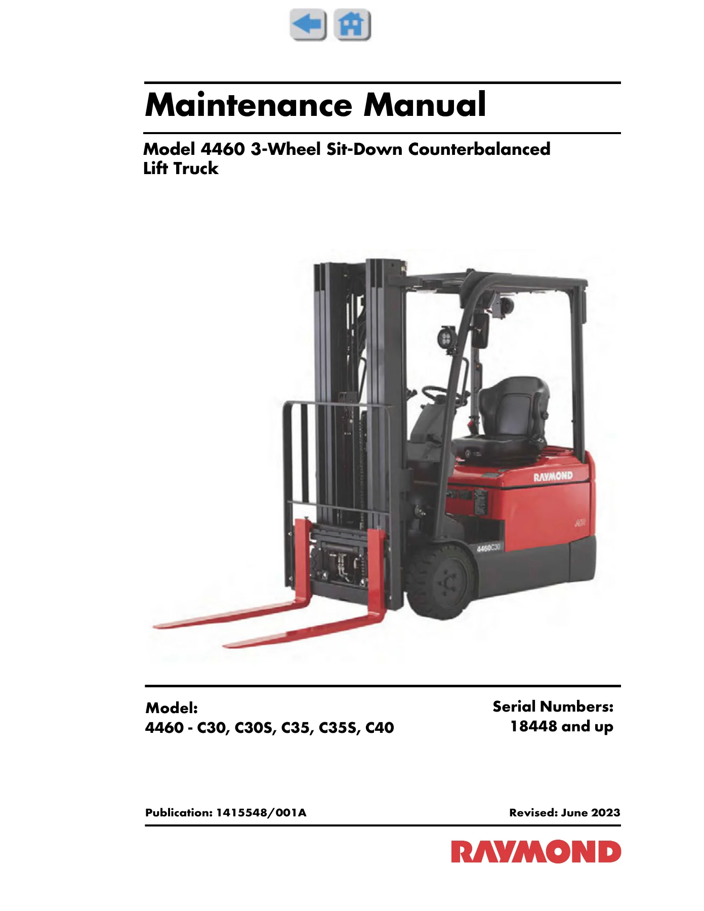
Raymond 4460 3-Wheel Counterbalanced Lift Truck Maintenance Manual – C30 C30S C35 C35S C40 PDF
Original price was: $39.95.$24.95Current price is: $24.95.
The complete Raymond 4460 Maintenance Manual for C30, C30S, C35, C35S and C40 3-wheel sit-down counterbalanced lift trucks, serial 18448 and up. Full service, repair, troubleshooting and specification reference in PDF.
Description
This is the full Raymond 4460 Maintenance Manual covering the 3-Wheel Sit-Down Counterbalanced Lift Truck series — models C30, C30S, C35, C35S and C40 from serial number 18448 and up. Published under document number 1415548A/001, this manual is the definitive service reference for these electric counterbalanced forklifts, providing the procedures, specifications and diagnostic guidance needed to maintain, troubleshoot and repair the trucks correctly.
File Details
- Manual type: Maintenance Manual
- Brand: Raymond
- Model series: 4460 3-Wheel Sit-Down Counterbalanced Lift Truck
- Covered models: C30, C30S, C35, C35S, C40
- Serial number coverage: 18448 and up
- Publication number: 1415548A/001
- Language: English
- File format: PDF
- Page count: Approximately 1,345 pages
- Publication year: 2023
Chapters Covered
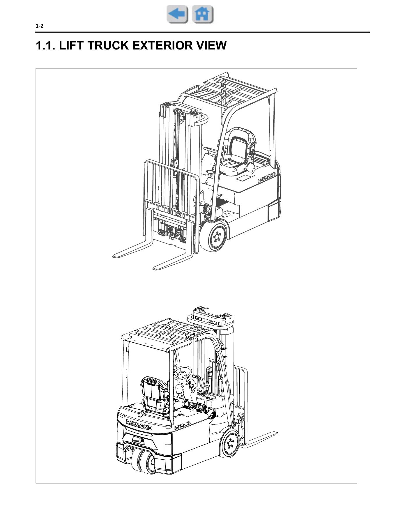
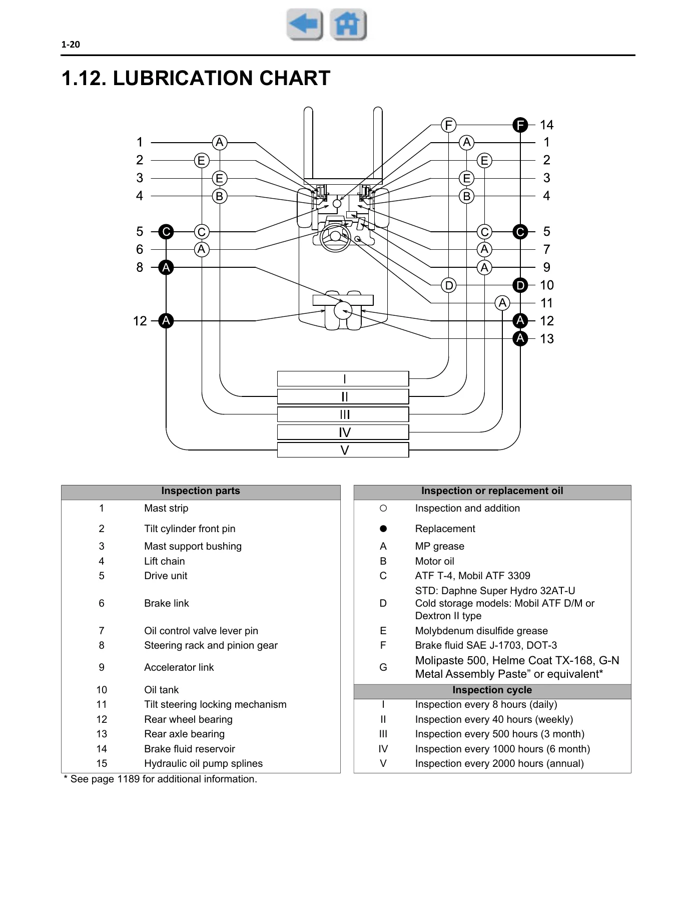
- General — exterior views, model identification, frame number location, operating tips, circuit tester use, standard bolt and nut tightening torques, precoat bolts, high-pressure hose fitting torque, component weights, recommended lubricants, lubrication chart, periodic maintenance table, periodic replacement table
- Battery — battery compartment and required weight, service standards, display, troubleshooting, battery assembly, battery plug terminal replacement, battery stopper
- Controller — general, electrical components layout, controller cable layout, specifications, before inspection, connector inspection, disassembly procedure, main controller, drive and pump motor driver, contactor panel (standard and UL-EE), fan, display, combination switch, accelerator sensor, brake sensor, brake switch adjustment, over current limit measurement
- Color Multi-Function Display — general, general functions, service functions, display assembly
- Troubleshooting — before troubleshooting, SST use, diagnosis code list, when a diagnostic code is displayed, when no diagnostic code is displayed, SEnS+ option troubleshooting
- Motor — drive motor (specifications, components, removal and installation, disassembly and reassembly), pump motor (specifications, components, removal and installation, disassembly and reassembly)
- Drive Unit and Front Axle — general, specifications, components, front axle hub and drive unit
- Rear Axle — rear axle assembly, rear axle hub, rear axle cylinder assembly, tire angle sensor
- Steering — general, specifications, components, steering wheel and mast jacket, hydrostatic steering valve assembly, relief pressure inspection and adjustment
- Brake — general, specifications, components, disc brake, brake air bleeding, braking force inspection and adjustment, brake master cylinder, electromagnetic brake, electromagnetic brake inspection and adjustment, brake pedal adjustment, urgent electromagnetic brake release
- Body & Frame — components, battery hood assembly, counterweight, operator’s seat, seat belt, camera bracket (SEnS+), fuse replacement
- Material Handling System — hydraulic circuit, components, component removal and installation, natural drop test, natural forward test, oil leak test
- Mast — TN mast assembly, TF/TT-CV/QM mast assembly, TT-OV mast assembly, chain, fork, lift cylinder rod shim adjustment
- Cylinder — lift cylinder (TN), rear lift cylinder (TF, TT-CV, QM), safety down valve, front lift cylinder (TF, TT-CV, QM), tilt cylinder, mast forward/backward tilt angle adjustment
- Oil Pump — general, components, removal and installation, disassembly and reassembly, test method
- Oil Control Valve — mechanically controlled valve, solenoid controlled valve, control valve lever assembly, relief pressure adjustment, manual down valve, troubleshooting
- Mini-Lever Controls — general, components, removal and installation, disassembly and reassembly
- PSS Functions — general, components, repair work, tilt angle sensor, load sensor, speed sensor, mast lifting height switch, tire angle sensor, matching, operator presence sensor, control specification, PSS caution label renewal
- Appendix — SST list, service standards, connector drawings, joint diagrams, connector locations, connecting diagrams, wiring diagrams, telematics and CAN-enabled LIB connection
What sets this Raymond 4460 service manual apart is its sheer depth. It is not a general guide — it is the full factory maintenance reference. Every major system on the truck is covered with complete disassembly, inspection and reassembly procedures: the AC drive and pump motors, the wet disc brake assemblies with electromagnetic brake release, the rear axle and steering cylinder, the hydrostatic steering valve, the multi-stage mast assemblies (TN, TF, TT-CV, TT-OV, QM), the lift and tilt cylinders, the oil pump and the oil control valve. The troubleshooting chapter alone spans hundreds of pages, with step-by-step diagnostic flowcharts keyed to every fault code the controller can produce. The appendix provides connector pinout drawings, joint diagrams, wiring schematics and service standards — all in one document.
What This Manual Enables You to Do
With this Raymond 4460 maintenance manual on hand, a technician can perform the full range of scheduled maintenance, diagnose and clear fault codes, test electrical circuits at the connector level, replace and adjust major components, and verify the truck is back within factory specifications. The diagnostic code list and the step-by-step troubleshooting procedures for each code mean you are not guessing — the manual tells you which connector to unplug, which pin to probe, what voltage or resistance to expect, and what to do if the reading is out of range. That level of detail cuts diagnostic time and prevents expensive trial-and-error parts replacement.
For routine maintenance, the periodic maintenance table and periodic replacement table lay out exactly what to inspect, measure, tighten, clean or lubricate at each interval — from daily checks to the 2000-hour service. The lubrication chart shows every grease point on the truck. The service standards section lists the wear limits for brakes, cylinders, masts, chains and forks, so you know when a part is still serviceable and when it must be replaced. Component weights are given for every major assembly, which matters when you are planning a lift or a rebuild. The manual also covers the special service tools (SSTs) used for bearing races, seals, cylinder covers and other press-fit components, so you can identify what you need before the truck is apart.
Who This Manual Is For
This Raymond 4460 lift truck maintenance manual is written for professional forklift technicians, fleet maintenance managers, and shop owners who service Raymond 3-wheel counterbalanced trucks. It is also valuable for a technically capable owner-operator who wants to understand the machine and perform their own maintenance correctly. Because it covers models C30, C30S, C35, C35S and C40 from serial 18448 and up, it applies to a broad range of trucks in that series. The procedures assume access to normal shop equipment and, in some cases, the specified SSTs, but the diagnostic and maintenance information is usable by anyone with a multimeter, basic hand tools and the willingness to follow the steps.
Note that this is a maintenance and service manual, not an operator’s manual. It does not replace the operator training materials that come with the truck. It is intended for maintenance and repair work.
IMAGES PREVIEW
Get instant access to the complete Raymond 4460 Maintenance Manual in PDF format. No shipping, no waiting — download it immediately after purchase and keep it on any device. Print the pages you need for the job, or search the PDF on a laptop or tablet in the shop. Whether you are diagnosing a fault code, rebuilding a brake assembly, adjusting a mast, or planning a major service, this manual gives you the factory procedures and specifications to do the job right.
Reviews
There are no reviews yet.