Raymond 537 Tractor & Mast Parts Catalog Manual SN 001 Thru 799 – PDF DOWNLOAD
Original price was: $78.95.$28.95Current price is: $28.95.
Raymond 537 Tractor & Mast Parts Catalog Manual SN 001 Thru 799 – PDF DOWNLOAD
Description
Raymond 537 Tractor & Mast Parts Catalog Manual SN 001 Thru 799 – PDF DOWNLOAD
FILE DETAILS:
Raymond 537 Tractor & Mast Parts Catalog Manual SN 001 Thru 799 – PDF DOWNLOAD
Language : English
Pages : 196
Downloadable : Yes
File Type : PDF
DESCRIPTION:
Raymond 537 Tractor & Mast Parts Catalog Manual SN 001 Thru 799 – PDF DOWNLOAD
Introduction to Your Parts Catalog:
Introduction:
The Raymond Corporation manufactures a variety of lift trucks in both standard and customized configurations. The Parts
Catalog is organized into major divisions which cover all areas of the truck. These may include:
• Power Unit (if applicable) • Hydraulic (if applicable)
• Brake and Steering • Elevating/ Attachments
• Drive Unit • Contadors
• Electrical • Special Options fif applicable)
Using the Catalog:
The catalog contains three elements necessary for effedive use, which are:
1. Quality Assurance Sheet gives specific components in a truck and is located at the beginning of the parts catalog.
2. Table of Contents guides the reader to the corred pages.
3. Customized Prints provide special documentation for customized trucks and are located at the end of the parts catalog.
Parts Catalog Overview:
• In some cases, large assemblies or installations are broken down over several pages.
Example: The DRIVE UNIT assembly is shown on one page — the DRIVE MOTOR for this drive unit on another page — the DRIVE WHEEL for this unit on another page.
• Drawings of hydraulic hoses and piping do not necessarily conform to exad installation as they appear on the truck.
These illustrations are for part number references only.
• An indented part number indicates the part is a component of the preceding non-indented part and can be ordered separately; however, the component will be included when the non-indented part is ordered.
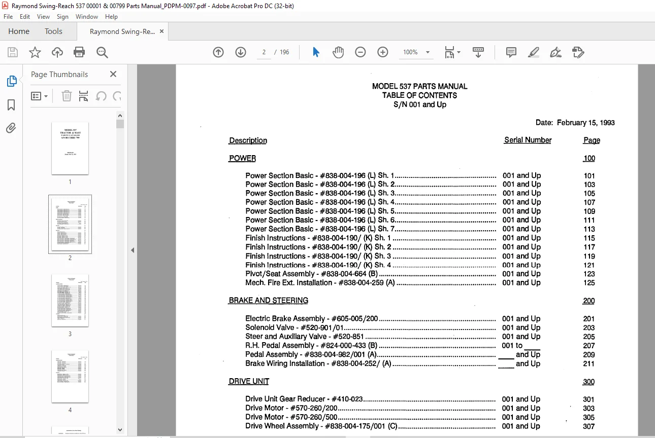
TABLE OF CONTENTS:
Raymond 537 Tractor & Mast Parts Catalog Manual SN 001 Thru 799 – PDF DOWNLOAD
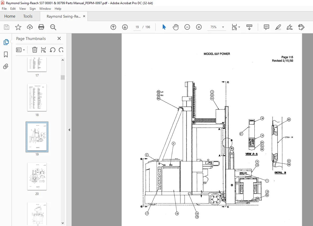
POWER
Power Section Basic – #838-004-196 (L) Sh 1 001 and Up
Power Section Basic – #838-004-196 (L) Sh 2 001 and Up
Power Section Basic – #838-004-196 (L) Sh 3 001 and Up
Power Section Basic – #838-004-196 (L) Sh 4 001 and Up
Power Section Basic – #838-004-196 (L) Sh 5 001 and Up
Power Section Basic – #838-004-196 (L) Sh 6 001 and Up
Power Section Basic – #838-004-196 (L) Sh 7 001 and Up
Finish Instructions – #838-004-190/ (K) Sh 1 001 and Up
Finish Instructions – #838-004-190/ (K) Sh 2 001 and Up
Finish Instructions – #838-004-190/ (K) Sh 3 001 and Up
Finish lnstructions – #838-004-190/ (K) Sh 4 001 and Up
Pivot/Seat Assembly – #838-004-664 (8) 001 and Up
Mech Fire Ext Installation – #838-004-259 (A) 001 and Up
BRAKE AND STEERING
Electric Brake Assembly- #605-005/200 001 and Up
Solenoid Valve – #520-901 /01 001 and Up
Steer and Auxiliary Valve – #520-851 ; 001 and Up
RH Pedal Assembly – #824-000-433 (B) 001 to
Pedal Assembly – #838-004-982/001 (A) and Up
Brake Wiring Installation – #838-004-252/ (A) ‘ = and Up
DRIVE UNIT
Drive Unit Gear Reducer- #410-023 001 and Up
Drive Motor – #570-260/200 001 and Up
Drive Motor – #570-260/500 001 and Up
Drive Wheel Assembly- #838-004-175/001 (C) 001 and Up
ELECTRICAL
Standard Electrical Symbols
Schematic – #838-004-435 (K) Sh 1
Schematic – #838-004-435 (K) Sh 2 ;
Schematic – #838-004-435 (K) Sh 3
Schematic – #838-004-435 (K) Sh 4
Final Assembly – #838-004-191 / (L) Sh 1
Final Assembly- #838-004-191/ (L) Sh 2
Final Assembly- #838-004-191/ (L) Sh 3
Final Assembly- #838-004-191 / (L) Sh 4
Electrical Control System – (Carriage Manager) – #838-004-598 (A)
Electrical Control System – (Carriage Manager) – #838-004-878 (A)
Electrical Control System – (Carriage Manager) – #838-004-973/001 (C)
Electrical Control System – (Vehicle Manager) – #838-004-599 (A):
Electrical Control System – (Vehicle Manager) – #838-004-871 (A)
Electrical Control System – (Vehicle Manager) – #838-004-971 /001 (D)
Card Cage Housing Assembly – #838-004-637 / (D)
Encoder Shaft Assembly – #838-004-647 (E)
Detector Assembly- #828-003-420/ (E)
001 and Up
001 and Up
001 and Up
001 and Up
001 and Up
001 and Up
001 and Up
001 and Up
001to174
175 to 299
300 and Up
001to174
175 to 299
300 and Up
001 and Up
001 and Up
001 and Up
Firmware Installation – #838-004-883/ (8)
Contactor Assembly – #838-004-793 (B)
Contactor Assembly – #838-004-876 (B3)
Transducer Module Assembly – #828-003-614/ (C)
Resistor Assembly – #838-004-198 (C) ;
Traverse Resistor Assembly – #838-004-549 (B)
Traverse Resistor Assembly – #838-007-049 (B)
Rotate Resistor Assembly – #838-004-550 (C)
Switch Assembly – #114-006-580/ (E) :
Mech Handles Installation – #838-004-607 / (A)
Mech Handles Installation – #838-004-607 / (B)
LH Control Arm Assembly – #838-004-708/ (E)
LH Control Arm Assembly – #838-004-789/ (AS)
LH Control Handle Assembly – #838-004-650 / (B) Sh 1
LH Control Handle Assembly – #838-004-650/ (B) Sh 2
LH Control Handle Assembly – #838-004-652/ (D1) Sh 1
LH Control Handle Assembly – #838-004-652/ (D1) Sh 2
RH Control Arm Assembly – #838-004-709/ (81)
RH Control Arm Assembly – #838-004-790/ (A3)
RH Control Handle Assembly – #838-004-651 / (B) Sh 1
RH Control Handle Assembly – #838-004-651 / (B) Sh 2
RH Control Handle Assembly – #838-004-653/ (D1) Sh 1
RH Control Handle Assembly – #838-004-653/ (D1) Sh 2
Warning Light Elec Installation – #838-004-636/ (C)
Warning Light Assembly – #114-007-671 / (A)
Elec Lights, Fan Installation – #838-004-623/ (E)
Cover and Fan Assembly – #838-004-710/ (D)
Cover and Bin Light Assembly – #838-004-711 / (C)
Travel Light Elec Installation – #838-004-633/ (8)
Gate Switch Elec Installation – #838-004-634 (A)
Wire Guidance Installation – #838-004-217 / (E)
Sensor Frame Assembly – #170-002-191 / (L)
Flow Sensor Module Assembly – #838-004-413 (8)
Flow Sensor Module Assembly – #838-004-880 (A)
Flow Sensor Module Assembly – #838-004-972/002 (C)
Lift Limit Electrical Installation – #838-004-858/ (C)
Heater Plate Assembly – #114-006-704/ (D)
Can Fuse Kit – #838-004-993 (8)
Power Option Electrical Installation – #838-004-969 (B)
HYDRAULIC
Standard Hydraulic Symbols
Serial Number
300 and up
001 to 174
175 and Up
001 and Up
001 and Up
001 to 466
467 and Up
001 and Up
001 and Up
001 to 109
110 and Up
001 to 109
110 and Up
001 to 109
001 to 109
110 and Up
110 and Up
001 to 109
110 and Up
001 to 109
001 to 109
110 and Up
110 and Up
001 and Up
001 and Up
001 and Up
001 and Up
001 and Up
001 and Up
001 and Up
001 and Up
001 and Up
001 to 174
175 to 299
300 and Up
001 and Up
001 and Up
389 and Up
001 and Up
Hydraulic Schematic – #838-004-134 (B) 001 and Up
Reservoir Assembly – #838-004-201 (C) 001 and Up
Platform Manifold Assembly – #838-004-402 (E) 001 and Up
Lift Pump – #500-420/ 001 and Up
Lift Motor – #570-261 /200 001 and Up
Auxiliary Pump – #500-417 /201 001 and Up
Auxiliary Motor – #570-222/100 001 and Up
Auxiliary Motor- #570-222/150 001 and Up
Auxiliary Motor- #570-222/200 001 and Up
Auxiliary Motor – #570-222/400 001 and Up
Tach Generator Assembly – #114-007-697 (A) 001 and Up
Hydraulic Motor- #550-017 001 to 263
Hydraulic Motor – #838-004-922/ 264 and Up
Reach/Rotate Valve – #520-853 001 and Up
Auxiliary Control Valve – #520-852 001 and Up
Solenoid Valve – #520-908 001 and Up
Solenoid Valve – #520-909 001 and Up
Hydraulic Motor – #550-019 001 and Up
Pump and Relief Valve – #520-849 , 001 and Up
Lift Select Valve – #520-850 001 and Up
ELEVATING
Elevating Section – #838-004-197 / (K) Sh 1 001 and Up
Elevating Section – #838-004-197 / (K) Sh 2 001 and Up
Elevating Section – #838-004-197 / (K) Sh 3 001 and Up
Auxiliary Mast Assembly – #838-004-520/ (K) Sh 1 001 and Up
Auxiliary Mast Assembly- #838-004-520/ (K) Sh 2 001 and Up
Auxiliary Mast Assembly – #838-004-520/ (K) Sh 3 001 and Up
Cylinder Assembly- #154-012-251/ (D2) 001 and Up
Cylinder Assembly – #154-012-207 / (D) 001 and Up
Cylinder Assembly – #540-060/ 001 to
Cylinder Assembly – #540-063/ and Up
Cylinder Assembly- #154-012-249/ (B4) 001 and Up
Mech Fork Installation – #838-004-194/ (C1) 001 and Up
Mech Tether Installation – #838-004-635/ (A) 001 and Up
IMAGES PREVIEW OF THE MANUAL:
Questions? Email us: [email protected]
https://vimeo.com/834404442?share=copy
PLEASE NOTE:
- This is the SAME MANUAL used by the dealerships to diagnose your vehicle
- No waiting for couriers / posts as this is a PDF manual and you can download it within 2 minutes time once you make the payment.
- Your payment is all safe and the delivery of the manual is INSTANT – You will be taken to the DOWNLOAD PAGE.
- So have no hesitations whatsoever and write to us about any queries you may have : heydownloadss @gmail.com
S.V