★ TRUSTED BY 321,897+ PROFESSIONALS WORLDWIDE
🏒
Trusted Business
Verified & Licensed
πŸ›‘οΈ
Virus Free Files
100% Safe Downloads
πŸ”’
Secure Payment
SSL Protected
⚑
Instant Delivery
Available Immediately
Sale!

Raymond 7500 & 7520 Reach-Fork Truck Parts Manual – 2013 PDF Download

Original price was: $34.95.Current price is: $20.95.

753-page illustrated parts manual for Raymond 7500 and 7520 Reach-Fork trucks. Covers R35TT, R45TT, DR32TT attachments, DC Lift, AC Lift, and Regen configurations with exploded views, part numbers, and complete hardware indexes.

⚑
Instant PDF Download
Available immediately
πŸ’Ύ
Save to Your Device
Download & keep forever
πŸ›‘οΈ
Antivirus Scanned
100% virus-free
🌍
Trusted Worldwide
175,000+ customers

Description

Raymond 7500 & 7520 Reach-Fork Truck Parts Manual

This is the complete illustrated parts manual for the Raymond 7500 and 7520 Reach-Fork trucks, document number 1112847, generated November 5, 2013. Whether you are maintaining a single truck in a warehouse fleet or supporting a mixed fleet of reach trucks across multiple shifts, having the correct part number the first time saves hours of downtime and eliminates the guesswork of ordering the wrong component. This Raymond 7500 & 7520 Reach-Fork Truck Parts Manual gives you direct access to every assembly, subassembly, and individual component used across both models in their many configurations.

File Details

  • Manual Type: Illustrated Parts Manual
  • Brand: Raymond
  • Models Covered: 7500, 7520
  • Document Number: 1112847
  • Date: November 5, 2013
  • Language: English
  • Page Count: 753
  • File Format: PDF

Chapters Covered

The manual opens with a general information section that includes three separate parts lists: hardware, critical parts, and recommended spare parts. From there it moves through every major system of the 7500 and 7520 Reach-Fork trucks, with each section containing exploded illustrations and itemized part numbers with quantities and service group references.

  • Section 1: General Information β€” Hardware (bolts, nuts, screws, washers, pins, rings, seals), Critical Parts (brake assembly, cylinders, chains, controllers, contactor panels, motors, pumps, manifolds), Recommended Spare Parts (bearings, belts, brushes, connectors, fuses, hoses, seals, sensors, switches, tires, valves, wheels)
  • Section 2: Finish & Accessories β€” Frame assembly (Dockstance and Fore/Aft Stance), battery roller assembly, finish instructions and decals, top cover installation and assembly, deadman and floor pad installation, battery covers and gates
  • Section 3: Steering & Controls β€” Steer linkage, steered idler wheel assembly, steer motor installation and assembly for DC and AC lift, steering wheel installation and assembly for all configurations, control handle installation and assemblies including ThermaKit variants, secondary control handle assemblies
  • Section 4: Drive & Brake β€” Drive unit installation and assembly, traction motor installation, brake installation and electric brake assembly, deadman pedal installation and assembly, drive wheel installation, inertial damper installation
  • Section 5: Electrical Components & System β€” Complete electrical system layouts for Fore/Aft Stance and Dockstance with Regen, AC Lift, and DC Lift, traction and lift power amplifier installation and assembly, vehicle manager, contactor panel installations and assemblies for standard, DC Lift, AC Lift, Regen Lower Only, and EE configurations, drive motor assembly, lift motor assembly (DC and AC), auxiliary motor assembly, operator display, horn, key switch, relay/control fuse panel, fuse relay circuit, battery connector, height encoder, limit switch, ambient temperature sensor, fan assemblies, speed limiting switch
  • Section 6: Hydraulic Components β€” Hose installations for all stance and lift configurations, reservoir installation and assembly for AC and DC lift, lift pump and motor installations and assemblies, auxiliary pump and motor installations and assemblies, lift pump assemblies (DC single and dual), lift pump manifold assembly, auxiliary pump, main manifold installations and assemblies for DC Lift, AC Lift, and Regen Only, auxiliary manifold, manifold assemblies for reach, tilt, and sideshift, cylinder assemblies for main lift, free lift (non-staging and staging), reach, tilt, and sideshift
  • Section 7: Mast β€” Mast to tractor mounting for 7500 and 7520, elevating sections for R35TT, R45TT, and DR32TT, main lift cylinder installations, free lift chain installation, free lift cylinder installations for DC and AC lift, cylinder and pulley bracket assembly, overhead guard installation, main lift hose assembly, over-the-mast hose and cable installations, carriage installations and assemblies for R35TT/R45TT and DR32TT, scissor assemblies, hose and cable installations at carriage, carriage assemblies for tilt with and without sideshift, Bolzoni sideshift carriage, mast guards, baseleg installations for all toe and straddle configurations, wheel plate installations, load wheel assembly, stop assemblies, forks
  • Section 8: Options & Kits β€” Load backrest, rear door installations, fire extinguisher, rear post and operator backrest, overhead guard covers, nested switch installations, Vantage Point System, security start switch, height-tilt indicator display, tilt carriage shims, RF adjustable linkage, operator compartment sensor system (OCSS), high performance air flow, travel light and alarm installations, working light and operator cooling fan harness and installation, fan assembly, warning light harness, strobe light, flashing light, iWarehouse RED, fork-laser system, battery gate alarm, iPort installation, high speed lift cut out, sideshift fitting guard, remote grease manifold, light and switch installation
  • Appendix A: Alphabetical Parts Index
  • Appendix B: Numerical Parts Index

This Raymond 7500 & 7520 Reach-Fork Truck Parts Manual is far more than a simple list of part numbers. Each section presents exploded-view illustrations that show how components fit together, with every item called out and cross-referenced to a part number, description, service group, and quantity. The critical parts list identifies the components that directly affect safety and machine operation. The recommended spare parts list helps maintenance planners stock the bearings, seals, belts, fuses, and switches that wear or fail most often. The alphabetical and numerical indexes at the back let you look up a part by name or by number, making it practical to work from either end of the identification process.

Models and Configurations Covered

The manual covers the Raymond 7500 and 7520 Reach-Fork trucks across a wide range of configurations. Attachment types include R35TT, R45TT, and DR32TT. Lift systems include DC Lift, AC Lift, and Regen Lower Only. Stance configurations include Fore/Aft Stance and Dockstance. Battery compartment sizes include 16.5 in., 18.5 in., and 21.5 in. Optional equipment such as ThermaKit, cold storage packages, EE (energy efficient) variants, and various light and alarm packages are included in Section 8. Because the manual covers so many configurations, it is important to match your truck’s specific options when ordering parts. The illustrations and part number groupings make that matching process straightforward.

How This Parts Manual Helps You

When a hydraulic hose fails on a 7520 with AC Lift and Regen, you need the exact hose assembly number for that configuration β€” not a generic replacement that might fit but might also cause flow restrictions or premature failure. When a contactor panel needs replacement on a 7500 with DC Lift, the manual shows the panel assembly, the individual contactors, the fuses, the bus bars, and the wiring harness as separate items so you can replace only what is needed. When a mast bearing starts making noise, the illustrated elevating section shows you exactly which bearing, stud, and shim combination is used in your mast configuration. This level of detail is what separates a correct repair from a comeback.

The Raymond 7500 & 7520 Reach-Fork Truck Parts Manual also supports planned maintenance. The recommended spare parts list tells you which bearings, seals, brushes, and filters to keep on the shelf. The critical parts list helps you identify the components that should never be substituted with a lower-grade alternative. The hardware lists at the front cover the bolts, nuts, washers, and pins used throughout the truck, so you can match Grade 8 flange bolts, Nord-Lock washers, and spiral pins precisely rather than grabbing whatever is in the bin.

Who This Manual Is For

This parts manual is written for forklift technicians, maintenance managers, parts departments, and fleet owners who need to identify and order components for Raymond 7500 and 7520 Reach-Fork trucks. It is equally useful for a technician performing a rebuild, a parts counter person looking up a number for a customer, or a fleet manager building a stocked parts crib. The exploded views and itemized lists make it practical to identify parts even if you are not already familiar with the truck’s internal layout. If you work on these trucks regularly, having the parts manual on hand means fewer calls to the dealer, faster parts ordering, and more accurate repairs.

Complete PDF Bookmark Tree

Complete Bookmarks

The complete bookmarks in the β€œRaymond 7500 & 7520 Reach-Fork Truck Parts Manual – 2013 PDF Download” are as follows:

Cover Pagep. 1
Table of Contentsp. 3
SECTION 1 General Informationp. 10
Hardwarep. 11
Criticalp. 23
Recommendedp. 34
SECTION 2 Finish & Accessoriesp. 44
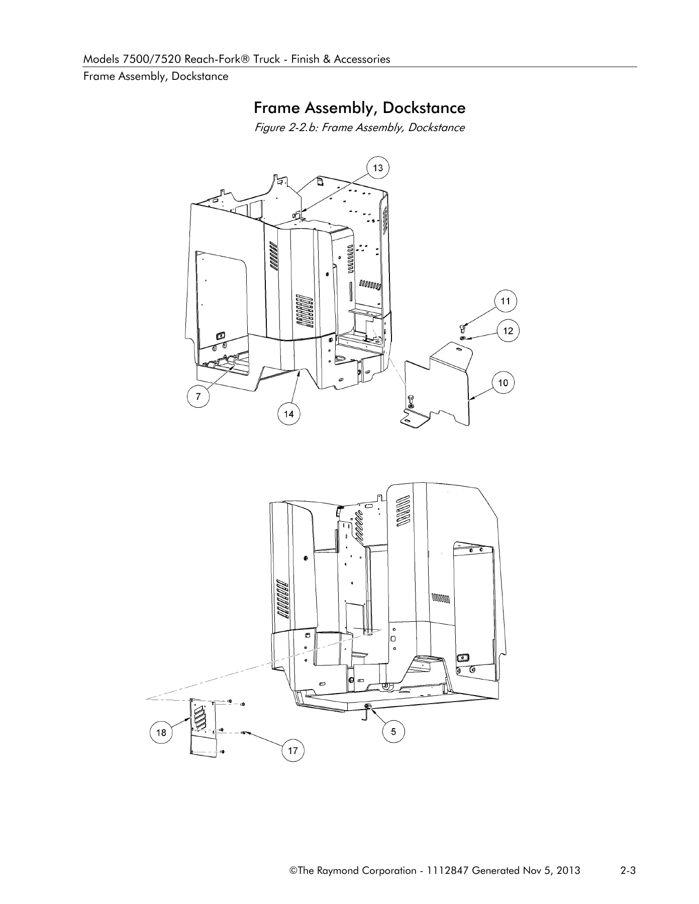
Frame Assembly, Dockstancep. 45
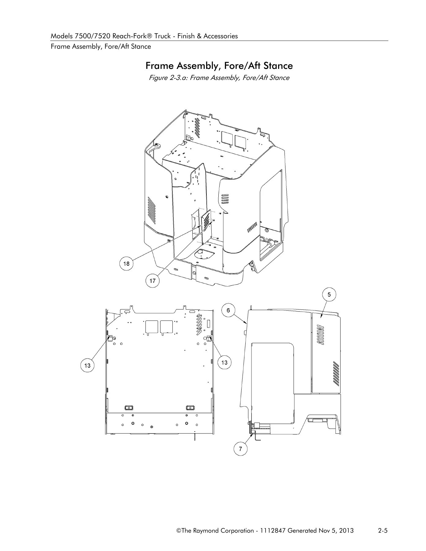
Frame Assembly, Fore/Aft Stancep. 48
Battery Roller Assemblyp. 51
Finish Instructionsp. 53
Finish Intructionsp. 61
Top Cover Installation, Fore/Aft Stancep. 71
Top Cover Assembly, Fore/Aft Stancep. 79
Top Cover Installation, Dockstancep. 82
Top Cover Assembly, Dockstancep. 87
Deadman and Floor Pad Installationp. 89
Battery Cover Installation, Steel Setp. 91
Battery Gate Installationp. 93
Battery Covers, EEp. 95
SECTION 3 Steering & Controlsp. 98
Steer Linkage Installationp. 99
Steered Idler Wheel Assemblyp. 103
Steer Motor Installation, DC Liftp. 105
Steer Motor Assembly, DC Liftp. 108
Steer Motor Installation, AC Liftp. 110
Steer Motor Assembly, AC Liftp. 113
Steering Wheel Installation, Fore/Aft Stance, DC Liftp. 115
Steering Wheel Installation, Fore/Aft Stance, AC Liftp. 118
Steering Wheel Assembly, Fore/Aft Stance, AC Liftp. 120
Steering Wheel Installation, Dockstance, DC Liftp. 122
Steering Wheel Installation, Dockstance, AC Liftp. 124
Steering Wheel Assembly, Dockstance, AC Liftp. 126
Control Handle Installationp. 128
Bracket Handle, Weldmentp. 130
Control Handle Assembly, Fore/Aft Stance, Primaryp. 132
Control Handle Assembly, Fore/Aft Stance, Primary, ThermaKitp. 137
Control Handle Assembly, Dockstancep. 141
Control Handle Assembly, Dockstance, Thermakitp. 145
Control Handle Installation, Fore/Aft Stance, Secondaryp. 149
Control Handle Assembly, Fore/Aft Stance, Secondaryp. 151
Control Handle Assembly, Fore/Aft Stance, Secondary, ThermaKitp. 153
Control Assembly Installationp. 156
SECTION 4 Drive & Brakep. 158
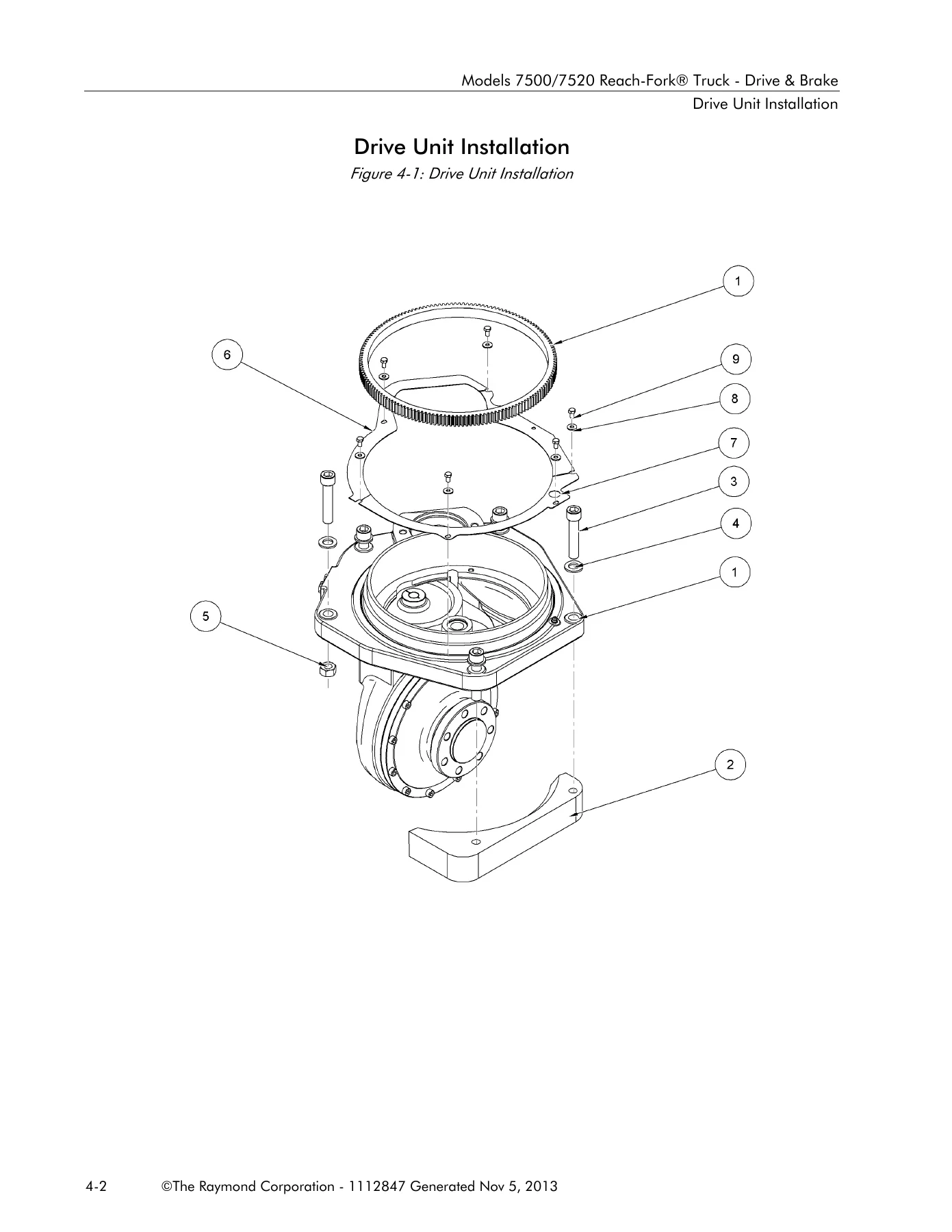
Drive Unit Installationp. 159
Traction Motor Installationp. 161
Drive Unit Assemblyp. 163
Brake Installationp. 166
Brake Assembly, Electricp. 168
Deadman Pedal Installationp. 170
Pedal Assembly, Deadmanp. 172
Drive Wheel Installationp. 174
Inertial Dampener Installationp. 176
SECTION 5 Electrical Components & Systemp. 178
Electrical System, Fore/Aft Stance With Regenp. 179
Electrical System, Fore/Aft Stance AC Liftp. 183
Electrical System, Fore/Aft Stance DC Liftp. 186
Electrical System, Dockstance With Regenp. 189
Electrical System, Dockstance, AC Liftp. 192
Electrical Systemp. 196
Traction Power Amplifier Installationp. 199
Traction Power Amplifier Assemblyp. 201
Lift Power Amplifier Installationp. 203
Lift Power Amplifier Assemblyp. 205
Vehicle Manager Installationp. 207
Contactor Panel Installation (STD)p. 209
Contactor Panel Assembly (DC Lift)p. 211
Contactor Panel Assembly (AC Lift)p. 213
Contactor Panel Installation Regen Lower Onlyp. 216
Contactor Panel Assembly Regen Lower Onlyp. 218
Contactor Panel Installation (EE)p. 221
Contactor Panel Assembly, EE, (DC Lift)p. 223
Contactor Panel Assembly, EE, (AC Lift)p. 225
Contactor Panel Installation, EE, Regen Lower Onlyp. 227
Contactor Panel Assembly, EE, Regen Lower Onlyp. 229
Contactor Assembly, Aux and Steerp. 231
Drive Motor Assemblyp. 233
Lift Motor Assembly, DCp. 235
Lift Motor Assembly, ACp. 237
Auxiliary Motor Assemblyp. 239
Operator Display Installation, Fore/Aft Stancep. 241
Display Installation Dockstancep. 243
Horn Installationp. 245
Switch Assembly, Keyp. 248
Relay/Control Fuse Panel Installation with Auxiliary Powerp. 250
Fuse Relay Circuit With Aux Powerp. 254
Battery Connector Installationp. 256
Battery Connector Assemblyp. 258
Height Encoder Installation Model 7500p. 260
Encoder Assembly, Height Indicatorp. 264
Guard-Height Sensing Installationp. 266
Encoder Installation Model 7520p. 268
Encoder Assembly, Height Indicator Model 7520p. 270
Limit Switch Installation, High Speed, End of Liftp. 272
Ambient Temperature Sensor Installationp. 274
Fan Assembly, Drive Motor Compartmentp. 276
Fan Assembly, Lift Motor Compartmentp. 278
Speed Limiting Switch (S12) Installationp. 280
SECTION 6 Hydraulic Componentsp. 282
Hose Installation, Dockstance, DC Liftp. 283
Hose Installation, Fore/Aft Stance, DC Liftp. 285
Hose Installation, Dockstance, AC Liftp. 287
Hose Installation, Fore/Aft Stance, AC Liftp. 289
Hose Installation, Dockstance, AC Lift With Regenp. 291
Hose Installation, Fore/Aft Stance, AC Lift With Regenp. 294
Reservoir Installation, AC Liftp. 296
Reservoir Assembly, AC Liftp. 298
Reservoir Installation, DC Liftp. 300
Reservoir Assembly, DC Liftp. 302
Lift Pump and Motor Installation, DC Liftp. 304
Lift Pump and Motor Installation, AC Liftp. 308
Lift Pump and Motor Assembly AC Liftp. 310
Lift Pump and Motor Installation With Regenp. 312
Lift Pump and Motor Assembly With Regenp. 314
Auxiliary Pump and Motor Installation, Dockstancep. 316
Auxiliary Pump and Motor Installation, Fore and Aft Stancep. 318
Auxiliary Pump and Motor Assemblyp. 320
Lift Pump Assembly, DC Singlep. 322
Lift Pump Assembly, DC, Dualp. 324
Lift Pump Manifold Assembly, Regenp. 326
Auxiliary Pumpp. 328
Main Manifold Installation, DC Liftp. 330
Main Manifold Assembly, DC Liftp. 332
Main Manifold Installation, AC Liftp. 336
Manifold Assemblyp. 338
Main Manifold Installation (Regen Only)p. 340
Manifold Assembly, Lift/Lower (Regen Only)p. 342
Auxiliary Manifold Installation With Regenp. 344
Manifold Assembly, Auxiliary, With Regenp. 346
Manifold Assembly, Reach, Tilt and Sideshift, R35TT and R45TTp. 348
Manifold Assembly, Reach, DR32TTp. 350
Manifold Assembly, Tilt, DR32TTp. 352
Manifold Assembly, Tilt and Sideshift, DR32TTp. 354
Cylinder Assembly, Main Lift, 7500p. 356
Main Lift Cylinder Assembly, 7520p. 358
Cylinder Assembly Free Lift, Non-Staging (DC Lift), R35TTp. 360
Cylinder Assembly, Free Lift, Staging, (AC Lift) R35TT, R45TT and DR32TTp. 362
Cylinder Assembly, Free Lift, AC Lift), Model 7520p. 365
Cylinder Assembly, Reachp. 367
Cylinder Assembly, Tiltp. 370
Cylinder Assembly, Sideshiftp. 372
SECTION 7 Mastp. 374
Mast to Tractor Mounting, 7500p. 376
Mast to Tractor Mounting, 7520p. 378
Elevating Section R35TTp. 380
Main Lift Cylinder Installation (R35TT)p. 386
Elevating Section R45TT and DR32TT (Model 7500)p. 389
Main Lift Cylinder Installation R45TT, DR32TTp. 395
Elevating Section, R45TT and DR32TT (Model 7520)p. 398
Main Lift Cylinder Installation, R45TT and DR32TT (Model 7520)p. 404
Free Lift Chain Installationp. 406
Free Lift Cylinder Installation (R35TT DC Lift)p. 409
Free Lift Cylinder Installation, 7500 (R35TT, R45TT AC Lift)p. 411
Free Lift Cylinder Installation 7500 (DR32TT AC Lift)p. 413
Cylinder and Pulley Bracket Assembly, Free Lift, Models 7520p. 415
Overhead Guard Installationp. 417
Main Lift Hose Assembly (Over The Mast)p. 419
Over The Mast Hose and Cable Installation (7500) R35TT, R45TT, DR32TTp. 421
Over The Mast Hose and Cable Installation (7520) R45TT and DR32TTp. 428
Carriage Installation, R35TT and R45TTp. 439
Reach Carriage Assembly, R35TT and R45TTp. 442
Scissor Assembly, R35TT and R45TTp. 448
Carriage Installation, DR32TTp. 450
Reach Carriage Assembly, DR32TTp. 453
Scissor Assembly, Deep Reach, DR32TTp. 458
Hose and Cable Installation, Carriage, R35TT and R45TTp. 462
Hose and Cable Installation, Carriage, DR32TTp. 466
Carriage Assembly, Tilt without Sideshift, R35TT and R45TTp. 469
Carriage Assembly, Tilt and Sideshift, R35TT and R45TTp. 471
Carriage Subassembly, Tilt and Sideshift, R35TT and R45TTp. 473
Carriage Assembly, Tilt without Sideshift, DR32TTp. 475
Carriage Assembly, Tilt and Sideshift, DR32TTp. 477
Carriage Sub Assembly, Sideshift, DR32TTp. 479
Carriage Assembly, Side Shift, Bolzonip. 481
Mast Guard Installation, Meshp. 484
Mast Guard Installation, Glassp. 486
Baseleg Installation, R35TT, 5 x 3.62 in., Open Toep. 488
Baseleg Installation, R35TT, 5 x 3.62 in., Straddle Closed Toep. 490
Baseleg Installation, R35TT, 5 x 2.88 in., Open Toep. 492
Baseleg Installation, R35TT, 5 x 2.88 in., Straddle Closed Toep. 494
Baseleg Installation, R35TT, 4 x 3.62 in., Closed Toep. 496
Baseleg Installation, R35TT, 4 x 2.88 in., Closed Toep. 498
Baseleg Installation, R45TT, 5 x 3.62 in., Open Toep. 500
Baseleg Installation, R45TT, 5 x 3.62 in., Closed Toep. 502
Baseleg Installation, R45TT, 5 x 2.88 in., Open Toep. 504
Baseleg Installation, R45TT, 5 x 2.88 in., Closed Toep. 506
Baseleg Installation, R45TT, 4 x 3.62 in., Closed Toep. 508
Baseleg Installation, R45TT, 4 x 2.88 in., Closed Toep. 510
Baseleg Installation, DR32TT, 5 x 3.62 in., Closed Toep. 512
Baseleg Installation, DR32TT, 5 x 2.88 in., Closed Toep. 514
Baseleg Installation, DR32TT, 4 x 3.62 in., Closed Toep. 516
Baseleg Installation, DR32TT, 4 x 2.88 in., Closed Toep. 518
Baseleg Installation, R45TT, 6 x 4 in., Open Toe (Model 7520)p. 520
Baseleg Installation, R45TT, 6 x 4 in., Closed Toe (Model 7520)p. 522
Baseleg Installation, 5 x 3.62 in., Closed Toe (Model 7520)p. 524
Wheel Plate Installation, Open Toe, 5 x 3.62 in.p. 526
Wheel Plate Installation, 6 x 4 in., Open Toep. 528
Wheel Plate Installation, 10.5 x 4.5 in., Open Toep. 530
Wheel Plate Installation, Closed Toe, Cast (All Except 6 x 4 in.)p. 534
Wheel Plate Installation, Closed Toe, Cast (6 x 4 in.)p. 537
Wheel Plate Installation, OWCTWB, 5 x 3.62 in. and 5 x 2.88 in.p. 539
Load Wheel Assemblyp. 541
Stop Assemblyp. 545
Stop Assembly, Sideshiftp. 547
Stop Assembly, Carriagep. 549
Forksp. 551
SECTION 8 Options & Kitsp. 557
Load Backrest Installationp. 558
Rear Door Installation, Fore/Aft Stancep. 561
Rear Door Installation, Dockstancep. 563
Fire Extinguisher Installationp. 565
Rear Post, Guard, Fore/Aft Stancep. 567
Rear Post and Operator Backrest Installation, Dockstancep. 569
Overhead Guard Coversp. 571
Nested Switch (S14) Installation, Standard Reachp. 573
Nested Switch (S14) Installation, Deep-Reachp. 575
Vantage Point Systemp. 578
Security Start Switchp. 585
Height-Tilt Indicator Display Installationp. 587
Tilt Carriage Shimsp. 589
RF Adjustable Linkage Installationp. 592
Operator Compartment Sensor System (OCSS), Fore/Aft Stancep. 595
Operator Compartment Sensor System (OCSS), Dockstancep. 598
High Performance Air Flow (DC Lift)p. 601
Travel Light and Alarm Installationp. 603
Travel Alarm Installationp. 608
Travel Light Installation, Incandesentp. 610
Travel Light Installation, LEDp. 612
Working Light and Operator Cooling Fan Harness Installationp. 614
Working Light and Operator Cooling Fan Installationp. 618
Travel Light and Fan Installation (LED)p. 620
Fan Assembly, Operator Coolingp. 622
Light Assembly, LEDp. 624
Fan Assembly, Operator Coolingp. 622
Warning Light Harness Installationp. 628
Strobe Light Installationp. 630
Flashing Light Installationp. 633
Light Assembly, Warning, Flashingp. 636
iWarehouse REDp. 638
Fork-Laser System Installationp. 640
Battery Gate Alarm Installationp. 645
iPort Installationp. 647
High Speed Lift Cut Out 24 inchp. 648
SideShift Fitting-Guard Installationp. 650
Manifold, Remote Grease, Installationp. 652
Light and Switch Installationp. 654
APPENDIX A Alphabetical Parts Indexp. 657
APPENDIX B Numerical Parts Indexp. 707

Why Choose This Digital Parts Manual

IMAGES PREVIEW

Raymond 7500 & 7520 Reach-Fork Truck Parts Manual - 2013 PDF Download β€” PDF page 46 preview
Raymond 7500 & 7520 Reach-Fork Truck Parts Manual - 2013 PDF Download β€” PDF page 48 preview
Raymond 7500 & 7520 Reach-Fork Truck Parts Manual - 2013 PDF Download β€” PDF page 159 preview

This Raymond 7500 & 7520 Reach-Fork Truck Parts Manual is delivered as an instant PDF download. There is no shipping wait, no physical book to keep track of, and no risk of losing the only copy in the shop. You can open it on a laptop, tablet, or phone, zoom into illustrations for detail, and print only the pages you need for a specific job. The PDF format makes it easy to search for part numbers, keep multiple copies in different locations, and share relevant sections with team members. Whether you are diagnosing a fault in the electrical system, rebuilding a mast, or ordering a replacement drive motor, this manual gives you the information you need in a format you can use immediately.

Stop guessing at part numbers and start working from the same illustrated parts information that authorized service providers use. Order your copy of the Raymond 7500 & 7520 Reach-Fork Truck Parts Manual today and get instant access to the complete parts breakdown for both models.
Reviews

There are no reviews yet.

Be the first to review “Raymond 7500 & 7520 Reach-Fork Truck Parts Manual – 2013 PDF Download”

What Our Customers Say

β˜…β˜…β˜…β˜…β˜… Live reviews from customers
Loading customer reviews...
0
    0
    Your Cart
    Your cart is emptyReturn to Shop
    πŸ›’
    Recently Purchased
    πŸ•’ verified order