Raymond 9800 Swing-Reach® Lift Truck With The ACR System ™ Maintenance Manual SN980-14-6301195 and Up – PDF DOWNLOAD
$32.95
Raymond 9800 Swing-Reach® Lift Truck With The ACR System ™ Maintenance Manual SN980-14-6301195 and Up – PDF DOWNLOAD
Description
Raymond 9800 Swing-Reach® Lift Truck With The ACR System ™ Maintenance Manual SN980-14-6301195 and Up – PDF DOWNLOAD
FILE DETAILS:
Raymond 9800 Swing-Reach® Lift Truck With The ACR System ™ Maintenance Manual SN980-14-6301195 and Up – PDF DOWNLOAD
Pages : 628
Downloadable : Yes
File Type : PDF
DESCRIPTION:
Raymond 9800 Swing-Reach® Lift Truck With The ACR System ™ Maintenance Manual SN980-14-6301195 and Up – PDF DOWNLOAD
- This manual is designed to provide personnel with an expected level of expertise the technical information necessary to maintain, troubleshoot, and repair a Raymond product.
- The two-line header at the top of each page provides the name of the manual, the title of the current section, and the topic of the page.
- The sections in this manual have Classification (C) Codes assigned to them. C-Code sections can include component procedures, theory of operation, troubleshooting information, and pin-out matrices. Schematic drawings showing the truck electrical system and the hydraulic system can be found in the respective section.
- This manual consists of the following sections:
TABLE OF CONTENTS:
Raymond 9800 Swing-Reach® Lift Truck With The ACR System ™ Maintenance Manual SN980-14-6301195 and Up – PDF DOWNLOAD
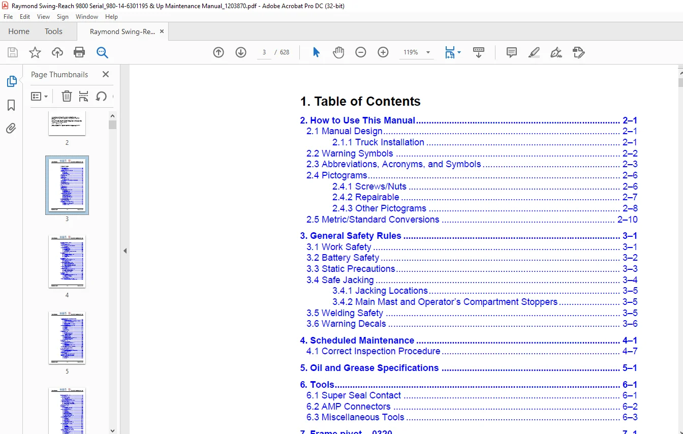
1 Table of Contents
2 How to Use This Manual 2–1
21 Manual Design 2–1
211 Truck Installation 2–1
22 Warning Symbols 2–2
23 Abbreviations, Acronyms, and Symbols 2–3
24 Pictograms 2–6
241 Screws/Nuts 2–6
242 Repairable 2–7
243 Other Pictograms 2–8
25 Metric/Standard Conversions 2–10
3 General Safety Rules 3–1
31 Work Safety 3–1
32 Battery Safety 3–2
33 Static Precautions 3–3
34 Safe Jacking 3–4
341 Jacking Locations 3–5
342 Main Mast and Operator’s Compartment Stoppers 3–5
35 Welding Safety 3–5
36 Warning Decals 3–6
4 Scheduled Maintenance 4–1
41 Correct Inspection Procedure 4–7
5 Oil and Grease Specifications 5–1
6 Tools 6–1
61 Super Seal Contact 6–1
62 AMP Connectors 6–2
63 Miscellaneous Tools 6–3
7 Frame pivot – 0320 7–1
71 Removal/Reassembly of Rear Chassis 7–1
711 Special Tools 7–1
712 Standard Hand Tools 7–1
713 Disassembly 7–2
714 Dismantle the Rear Chassis 7–11
72 Replacing the Bearing Frame Links 7–12
721 Remove the Old Bearings 7–12
722 Install New Bearings 7–13
723 Reinstall the Rear Chassis 7–16
724 Reassemble the Truck 7–17
725 Lower the Truck to the Ground 7–18
726 Final Assembly 7–18
8 General Tightening Torque – 0400 8–1
81 Galvanized, Non-Oiled Bolts 8–1
82 Untreated, Lubricated Bolts 8–1
9 AC Pump Motor, C Code 17101, Main Lift 9–1
91 Description 9–1
911 Replacing the Temperature Sensor 9–3
912 Replacing the Speed Sensor 9–4
913 Replacing Bearings 9–7
Publication: 1203870 1 – 2 Issued: 20 Jan 2016
Table of Contents Model 9800 Swing-Reach® Lift Truck
10 Electric DC Pump Motor – 17102 10–1
101 General 10–1
102 Disassembled Pump Motor 10–1
1021 Connection 10–1
103 Disassembly and Assembly of the Pump Motor 10–2
1031 Disassembly 10–2
1032 Installation 10–3
104 Replacing the Ball Bearing 10–4
1041 Disassembly (D side) 10–4
1042 Installation 10–4
1043 Disassembly (N side) 10–5
1044 Assembly (N side) 10–5
1045 Carbon Brushes and Carbon Brush-Rocker 10–5
11 AC Drive Motor, C Code 1760 11–1
111 Description 11–1
1111 Replacing the Temperature Sensor 11–2
1112 Replacing the Speed Sensor 11–2
1113 Disassembly 11–3
1114 Replacing Bearings 11–6
1115 Assembly 11–8
12 Drive Unit/Gear – 2550 12–1
121 General 12–1
122 Components/Data of the Drive Unit and Gear 12–1
1221 Component Identification 12–2
1222 Technical Data 12–4
1223 Dismantled Gear 12–4
123 Replacing the Drive Motor/Drive Gear 12–4
1231 Dismantling of Drive Unit from Truck 12–5
1232 Installing the Drive Unit in Truck 12–5
1233 Dismantling the Drive Motor and the Gear 12–6
1234 Installing the Drive Motor and the Gear 12–6
124 Oil Level Check/Replacement 12–7
1241 Checking/Refilling the Oil 12–7
1242 Oil Change 12–7
125 Repairs 12–8
1251 Replacing the Drive Axle Jointing Ring 12–9
1252 Leakage from the Top Cover 12–10
1253 Leakage from the Lower Cover 12–10
1254 Replacing the Wheel Bolts 12–11
13 Brake System – 3100 13–1
131 General 13–1
132 Description of Functions 13–1
1321 Releasing the Directional/Speed Control Knob 13–1
1322 Travel Direction Selector 13–1
1323 Pressing the Brake Button 13–1
1324 Parking Brake 13–3
1325 Emergency Braking 13–3
133 Electro-Mechanical Disc Brake, Drive Motor 13–3
1331 Maintenance Schedule and Maintenance Work 13–4
Publication: 1203870 1 – 3 Issued: 20 Jan 2016
Table of Contents Model 9800 Swing-Reach® Lift Truck
134 Replacing Brake Unit and Dismantling Brake Unit to
Replace Friction Disc 13–5
1341 Replacing the Brake Unit 13–5
1342 Dismantling a Brake Unit/Checking/Replacing a Brake Disc 13–7
1343 Check and Adjust the Brake Force 13–8
1344 Clean 13–8
1345 Checking the Air Gap 13–8
1346 Checking and Adjusting the Brake Force 13–9
1347 Troubleshooting 13–9
135 Disc Brake with Multiple Discs, Support Arms 13–10
1351 Checking the Play/Wear 13–10
1352 Dismantling 13–11
1353 Inspection 13–12
1354 Installation 13–12
1355 Maintenance 13–12
1356 Adjusting the Play 13–13
14 Wheels – 3500 14–1
141 Drive Wheels – 3530 14–1
1411 General 14–1
1412 Disassemble the Drive Wheel 14–1
1413 Assembling the Drive Wheel 14–1
1414 Available Wheel Qualities 14–2
142 Support Arm Wheels – 3550 14–2
1421 Dismantling the Wheel 14–2
1422 Assembling the Wheel 14–4
1423 Dismantling/Assembling the Wheel Bearings 14–5
1424 Support Arm Wheels, Shimming 14–6
1425 Available Wheel Qualities 14–6
15 Steering System – 4000 15–1
151 General 15–1
1511 Steering Components 15–3
1512 Hydraulic Diagram, Steering System 15–4
152 Function Description 15–5
1521 Electrical System 15–5
1522 Replacing the Steering Angle Sensor 15–7
1523 Hydraulic System 15–9
1524 Temperature and Voltage Compensation 15–9
153 Troubleshooting 15–10
1531 Operations/Repair, Hydraulics 15–10
16 Steering Cylinder – 4160 16–1
161 Instructions for Checking for Internal Leaks 16–1
1611 Checks Made Together with 2000-Hours Service 16–1
1612 When Wear is Suspected 16–1
162 Recommended Procedure 16–1
163 Remedial Actions 16–3
1631 Procedure 16–3
164 Removing a Steering Cylinder from the Truck 16–4
165 Installing a Steering Cylinder on the Truck 16–6
166 Repairs to the Front Steering Cylinder Mount 16–7
1661 Background 16–7
1662 Repair Material 16–7
1663 Measures 16–7
Publication: 1203870 1 – 4 Issued: 20 Jan 2016
Table of Contents Model 9800 Swing-Reach® Lift Truck
17 Wire Guidance System – 4500 17–1
171 Wire Guidance 17–1
1711 General 17–1
172 Wire Guidance Components 17–3
1721 Antennas, W1, W2 17–4
1722 Travel Speeds 17–11
1723 Description of the Function 17–13
173 “Best Practice” for Adjusting the Wire Guidance 17–20
1731 Set-Up Procedure 17–20
174 Parameters 17–22
1741 General Wire Guidance Parameters 17–22
1742 Learned Calibration Values, Steering 17–22
1743 Learned Calibration Data, Wire Guidance 17–22
175 Warning and Fault Codes 17–22
18 Electrical System – 5000 18–1
181 General 18–1
1811 Terminology 18–3
1812 Truck Firmware Applications 18–3
1813 Communication 18–3
182 Main Computer Unit (MCU) (A5) 18–4
1821 General 18–4
1822 Voltage Feed 18–6
1823 Battery Negative 18–6
1824 Electric Connectors 18–6
1825 Internal Status Monitoring 18–6
1826 Resetting the Battery Indicator 18–7
1827 External Inputs and Outputs 18–7
1828 Installing a New Card in the Truck 18–10
1829 Programming the MCU 18–10
183 Fork Control Unit (FCU) (A4) 18–11
1831 General 18–11
1832 Voltage Feed 18–12
1833 Battery Negative 18–12
1834 Electric Connectors 18–12
1835 Safety Measure 18–12
1836 External Inputs and Outputs 18–12
1837 Installing a New Card in the Truck 18–13
1838 Programming 18–13
184 Integrated Control Panel (ICP) (A16) 18–14
1841 General 18–14
1842 ICP Modules 18–16
1843 Voltage Feed 18–17
1844 Battery Negative 18–17
1845 External Inputs and Outputs 18–18
1846 Installing a New ICP in the Truck 18–20
1847 Programming 18–20
185 Motor Controllers, ACTL (A1), ACTR (A31),
and ACH (A2) Generation 5 18–21
1851 General 18–21
1852 ACT Regulators, A1/A31 18–22
1853 ACH Regulator, A2 18–24
1854 Troubleshooting 18–26
1855 Connection of Power Cables 18–38
Publication: 1203870 1 – 5 Issued: 20 Jan 2016
Table of Contents Model 9800 Swing-Reach® Lift Truck
1856 Installing a New Frequency Converter in the Truck 18–38
1857 Programming 18–38
1858 Maintenance 18–39
1859 Safety 18–39
18510 Cleaning 18–39
186 DC Regulator, DCHI (A32) 18–39
1861 General description 18–39
1862 Connection Terminal and Terminal Pillars 18–41
1863 Technical Data 18–41
1864 Installing a New Transistor Panel 18–41
187 Parameters 18–42
188 Diagnostics and Troubleshooting 18–42
1881 Maintenance 18–44
1882 Safety 18–44
1883 Cleaning 18–44
189 Hand-Held Terminal 1307 18–45
1891 Using the Hand-Held Terminal 18–47
1892 Viewing and Adjusting Parameters 18–48
1893 SPECIAL PROGRAM MODE 18–49
1894 Using the TEST Mode 18–49
1895 Using the DIAGNOSTICS MODE 18–49
1896 SPECIAL DIAGNOSTICS MODE 18–50
1810 Electric System, Overview 18–51
1811 Symbol List and Electrical Schematic 18–55
18111 List of Symbols 18–55
1812 Electrical Schematic 18–57
1813 Component Location 18–92
18131 Cabling Contacts 18–101
1814 Functional Description, General 18–104
1815 Functional Description, Starting, Driving, Steering and Braking 18–105
18151 Battery Connected, Truck Switched OFF 18–105
18152 Log-in/Start-up 18–105
18153 Log-out/Switch-OFF 18–108
18154 Presence Check 18–109
18155 Selecting the Drive Direction/Driving 18–109
18156 Service Mode 18–111
18157 Travel Speeds 18–111
18158 Steering 18–113
18159 Braking 18–113
1816 Electrical Description of the Hydraulic Functions 18–119
18161 Allowed Combined Functions 18–119
18162 Monitoring and Functional Limitations 18–120
18163 Slack Chain Guard 18–121
18164 Height Measurement 18–122
18165 Operator’s Compartment Lifting 18–124
18166 Special Height (Lift Limiter Function) 18–126
18167 Operator’s Compartment Lowering 18–127
18168 Operator’s Compartment Lift/Lower with
Forks Set Straight Ahead 18–129
1817 Turret Head Unit 18–130
1818 Miscellaneous Electrical Functions 18–141
1819 Narrow Aisle ID System 18–142
Publication: 1203870 1 – 6 Issued: 20 Jan 2016
Table of Contents Model 9800 Swing-Reach® Lift Truck
1820 Display 18–143
18201 Normal Mode 18–143
18202 Information Mode 18–145
19 Parameters – 5700 19–1
191 General 19–1
192 Accessing Parameters 19–2
1921 Operator Parameters 19–2
193 Truck Parameters 19–4
1931 MCU Parameters 19–6
1932 MCU Parameters 19–31
1933 FCU Parameters, Turret Head Fork Unit 19–32
1934 ICP Parameters 19–40
20 Calibration – 5700 20–1
201 General 20–1
2011 Accessing Calibration Mode 20–1
2012 Menu Navigation 20–2
202 Calibration of the ICP Controls – “CONTROLS” 20–3
203 Calibration of Steering – “STEERING” 20–4
2031 Calibration of the Articulated Center Potentiometer 20–4
2032 Calibration of the Control Valves 20–5
204 Calibration of Wire Guidance – “WIRE” 20–6
2041 “Learn Offset” 20–6
2042 Learn Frequency 20–6
205 Calibration of Turret Head Fork Unit Functions – “FORKS” 20–7
2051 Counterclockwise Rotation 20–7
2052 Clockwise Rotation 20–7
2053 Calibration of Traversing/Lifting, “TRAV/LIFT” 20–8
2054 Fork Lowering – “LOWER” 20–9
206 Calibration of Weight Indication – “WEIGHT” 20–10
207 Calibration of B Cylinder Pressure – “PRESSURE” 20–11
208 Calibration of Height Indication 20–12
209 Learn Status Codes – FCU 20–14
21 Fault Codes – 5700 21–1
211 General 21–1
212 Warning and Fault Codes 21–1
2121 System Response Logic 21–3
213 Fault Codes, Description 21–4
2131 ICP, Code Group 1 21–4
2132 MCU, Code Group 2 21–11
2133 Drive System, Code Group 3 21–19
2134 Operator’s Compartment Lift System, Code Group 4 21–27
2135 Steering System, Code Group 5 21–33
2136 Mini-Mast and Turret Head Fork Unit Systems,
Code Group 6 21–48
22 Hydraulic System – 6000 22–1
221 General 22–1
222 Hydraulic Cleanliness 22–1
2221 Packaging 22–1
2222 Handling 22–1
2223 Storage 22–2
2224 Work Procedures 22–2
2225 Inspection Measures 22–2
Publication: 1203870 1 – 7 Issued: 20 Jan 2016
Table of Contents Model 9800 Swing-Reach® Lift Truck
223 Symbols 22–3
224 Hydraulic Schematics 22–5
225 Operator’s Compartment Lifting 22–12
2251 General 22–12
2252 Operator’s Compartment Lifting – S44 closed 22–12
2253 Operator’s Compartment Lowering – S70 closed 22–12
2254 AC Hydraulic Unit, Components 22–13
2255 Hydraulic Flow Diagram, Operator’s Compartment Lifting 22–14
2256 B Cylinder System 22–15
226 Mini-Mast And Steering 22–17
2261 General 22–17
2262 Hydraulic Flow Diagram – Mini-Mast and Steering 22–18
2263 Fork Rotation 22–21
2264 Traversing 22–21
2265 Mini-Mast Lifting 22–22
2266 Mini-Mast Lowering 22–22
2267 Steering 22–22
227 Extra Hydraulic Function 22–23
2271 Valves Used for the Extra Hydraulic Functions 22–23
2272 Hydraulic Diagram, Extra Hydraulic Function 22–24
228 Operations/Repair 22–25
2281 General 22–25
2282 Filter 22–26
2283 Hydraulic Connections 22–28
2284 General Repair Instructions, Valves 22–34
23 Hydraulic Tank – 6110 23–1
231 Replace the Hydraulic Oil 23–1
2311 Emptying the Tank 23–1
2312 Filling the Tank 23–2
232 Tank Removal 23–2
233 Installing a New Tank 23–6
24 Hydraulic Pump – 6140 24–1
241 General 24–1
242 Bleeding the Hydraulic Pumps 24–3
2421 Bleeding the Hydraulic Pump for Steering
and Fork Hydraulics (B) 24–3
2422 Bleeding the Hydraulic Pump for Main Lift (A1, A2) 24–4
243 Replacing the Hydraulic Pump for Main Lift (A1, A2) 24–4
2431 Disassembly 24–4
2432 Installation 24–6
244 Replacing the Hydraulic Pump for Steering and Fork Hydraulics (B) 24–8
2441 Disassembly 24–8
2442 Installation 24–10
245 Troubleshooting Internal Leakage in the Hydraulic Pump
for Steering and Fork Hydraulics (B) 24–12
25 Accumulators – 6280 25–1
251 Charging of the Lifting and Steering Accumulators 25–1
2511 Preparations 25–2
2512 Measuring the Pressure in the Lifting Accumulator 25–3
2513 Charging the Lifting Accumulator 25–6
252 Measuring the Pressure in the Steering Accumulator 25–7
2521 Charging the Steering Accumulator 25–8
Publication: 1203870 1 – 8 Issued: 20 Jan 2016
Table of Contents Model 9800 Swing-Reach® Lift Truck
26 Main Lift Cylinder – 6610 26–1
261 Replacing the Seal in the B Cylinder 26–1
27 Main Mast and Mast Stoppers – 7100 27–1
271 Setting the Operator’s Compartment and Mast Stoppers 27–1
2711 Operator’s Compartment Stoppers 27–1
2712 Setting the Operator’s Compartment Stoppers 27–2
2713 Mast Stoppers 27–5
28 Main Lift Chain System – 7120 28–1
281 Checking the Chain Setting 28–1
282 Checking the Chain 28–1
2821 Noise 28–1
2822 Surface Rust 28–1
2823 Rusty Links 28–1
2824 Stiff Links 28–1
2825 Bolt Rotation 28–2
2826 Loose Bolts 28–2
2827 Outline Wear 28–2
2828 Stretching 28–3
2829 Damage 28–4
28210 Damaged Discs 28–4
28211 Damaged Bolts 28–4
28212 Dirty Chain 28–4
283 Cleaning 28–4
284 Lubrication 28–5
285 Adjusting Chains 28–6
2851 Tool List 28–6
2852 Main Lift Chain Adjustment 28–6
2853 Operator’s Compartment Chain Adjustment 28–8
2854 Mini-Mast Chain Adjustment 28–8
29 Mini-Mast/Turret Head Fork Unit – 7200 29–1
291 General Description 29–1
292 Assembly/Disassembly of the Mini-Mast 29–2
2921 Mast Assembly 29–2
2922 Mast Disassembly 29–8
293 Inspection/Replacement of Belts Used for Fork Traversing 29–9
2931 Check 29–9
2932 Replacing the Belt 29–9
2933 Checking Belt Tension 29–12
294 Friction Plate Adjustment 29–14
295 Parallel Adjustment of Forks 29–15
2951 Measuring Fork Parallelism 29–15
2952 Adjusting Fork Parallelism 29–16
30 End-of-Aisle Slowdown and Stopping – 8100 30–1
301 End-of-Aisle Slowdown 30–1
302 End-of-Aisle Stop 30–3
303 Parameters to check/adjust 30–4
Publication: 1203870 1 – 9 Issued: 20 Jan 2016
Table of Contents Model 9800 Swing-Reach® Lift Truck
31 Vertical Hold – 9390 31–1
311 General 31–1
312 Parameters 31–1
3121 MCU Parameters 31–1
313 Programming 31–2
3131 To Program the Fork Level (Option) 31–3
3132 Using Vertical Hold 31–4
32 Preparation for Transport 32–1
321 General 32–1
322 Tool List 32–1
323 Dismantling the Truck 32–2
324 Laying Down the Truck 32–11
Appendix A: TruckCom A–1
A1 InstallationA–2
A11 TruckCom A–2
A12 Start TruckCom A–4
A13 License Key Retrieval (required at first start-up only) A–4
A14 Installing USB/CAN interface drivers A–6
A141 CAN interfaces A–6
A142 Updating software in the USB/CAN Interface A–7
A2 Retrieving/Downloading Software A–8
A21 PC users A–8
A22 TruckCom Dialog Box A–9
A3 Connecting to TruckA–10
A4 Using TruckComA–11
A41 Navigating Drop-down Lists A–13
A411 Node Drop-down List A–13
A412 Action Drop-down List A–13
Index I–1
IMAGES PREVIEW OF THE MANUAL:
Customer Support: [email protected]
PLEASE NOTE:
- This is the same manual used by the DEALERSHIPS to SERVICE your vehicle.
- The manual can be all yours – Once payment is complete, you will be taken to the download page from where you can download the manual. All in 2-5 minutes time!!
- Need any other service / repair / parts manual, please feel free to contact us at heydownloadss @gmail.com . We may surprise you with a nice offer
S.M