Raymond Forklift 20 Tractor Resistor & SCR Parts Catalog Manual SN 21000 Thru 28999 – PDF DOWNLOAD
Original price was: $78.95.$28.95Current price is: $28.95.
Raymond Forklift 20 Tractor Resistor & SCR Parts Catalog Manual SN 21000 Thru 28999 – PDF DOWNLOAD
Description
Raymond Forklift 20 Tractor Resistor & SCR Parts Catalog Manual SN 21000 Thru 28999 – PDF DOWNLOAD
FILE DETAILS:
Raymond Forklift 20 Tractor Resistor & SCR Parts Catalog Manual SN 21000 Thru 28999 – PDF DOWNLOAD
Language : English
Pages : 256
Downloadable : Yes
File Type : PDF
DESCRIPTION:
Raymond Forklift 20 Tractor Resistor & SCR Parts Catalog Manual SN 21000 Thru 28999 – PDF DOWNLOAD
Introduction to Your Parts Catalog:
Introduction:
The Raymond Corporation manufactures a variety of lift trucks in both standard and customized configurations. The Parts
Catalog is organized into major divisions which cover all areas of the truck. These may include:
• Power Unit (if applicable) • Hydraulic (if applicable)
• Brake and Steering • Elevating/ Attachments
• Drive Unit • Contadors
• Electrical • Special Options fif applicable)
Using the Catalog:
The catalog contains three elements necessary for effedive use, which are:
1. Quality Assurance Sheet gives specific components in a truck and is located at the beginning of the parts catalog.
2. Table of Contents guides the reader to the corred pages.
3. Customized Prints provide special documentation for customized trucks and are located at the end of the parts catalog.
Parts Catalog Overview:
• In some cases, large assemblies or installations are broken down over several pages.
Example: The DRIVE UNIT assembly is shown on one page — the DRIVE MOTOR for this drive unit on another page — the DRIVE WHEEL for this unit on another page.
• Drawings of hydraulic hoses and piping do not necessarily conform to exad installation as they appear on the truck.
These illustrations are for part number references only.
• An indented part number indicates the part is a component of the preceding non-indented part and can be ordered separately; however, the component will be included when the non-indented part is ordered.
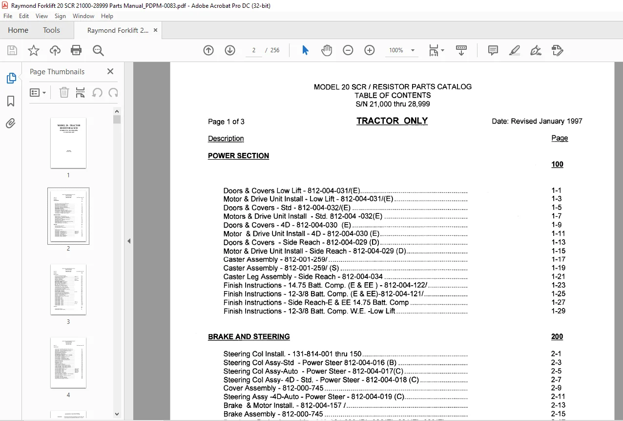
TABLE OF CONTENTS:
Raymond Forklift 20 Tractor Resistor & SCR Parts Catalog Manual SN 21000 Thru 28999 – PDF DOWNLOAD
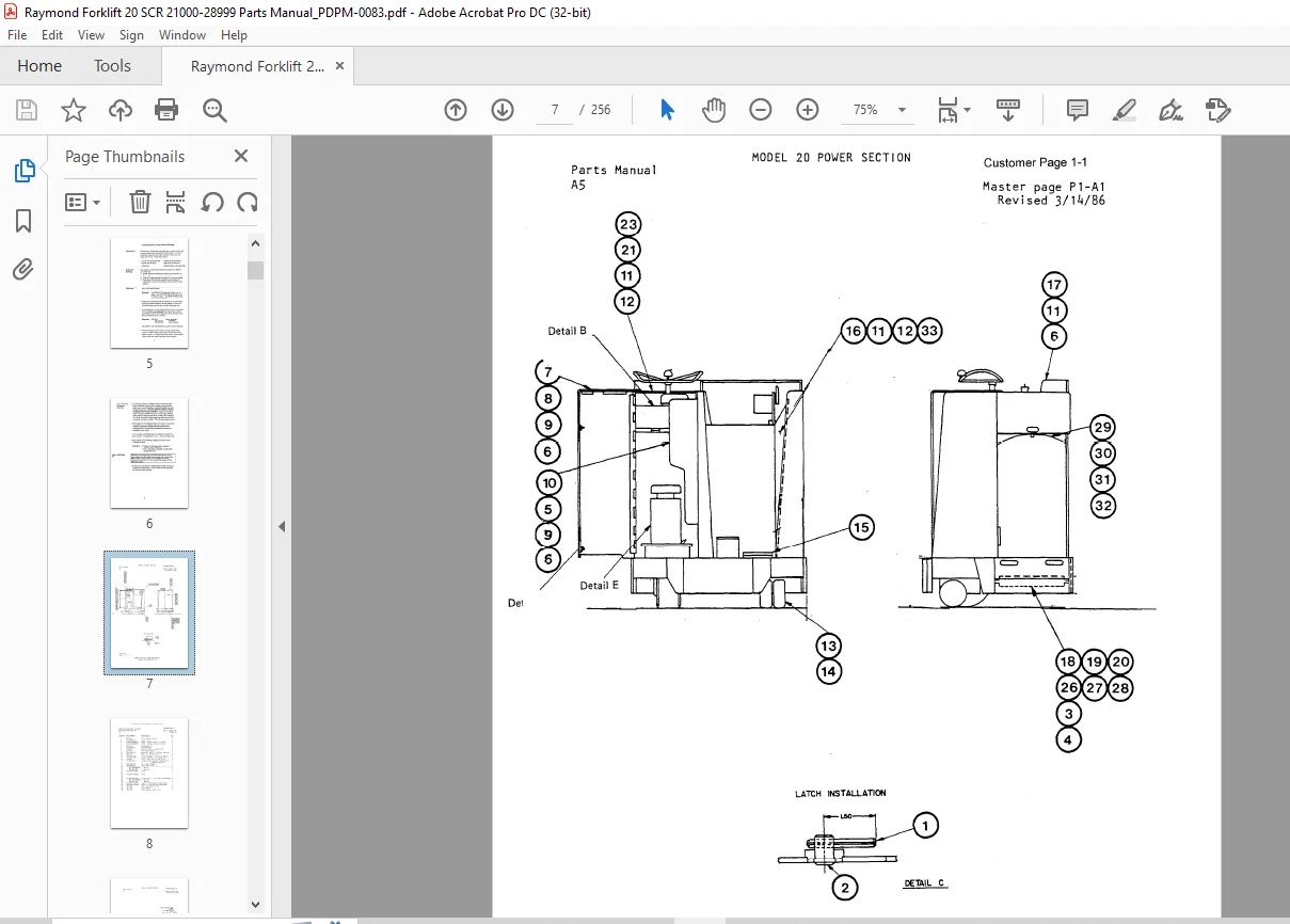
POWER SECTION
MODEL 20 SCR / RESISTOR PARTS CATALOG
TABLE OF CONTENTS
S/N 21,000 thru 28,999
TRACTOR ONLY Date: Revised January 1997
Doors & Covers Low Lift- 812-004-031/(E) 1-1
Motor & Drive Unit Install – Low Lift- 812-004-031/(E) 1-3
Doors & Covers – Std – 812-004-032/(E) 1-5
Motors & Drive Unit Install – Std 812-004 -032(E) 1-7
Doors & Covers – 4D – 812-004-030 (E) 1-9
Motor &DriveUnitlnstall-4D-812-004-030(E) 1-11
Doors & Covers -Side Reach – 812-004-029 (D) 1-13
Motor & Drive Unit Install – Side Reach – 812-004-029 (D) 1-15
Caster Assembly – 812-001-259/ 1-17
Caster Assembly – 812-001-259/ (S) 1-19
Caster Leg Assembly – Side Reach – 812-004-034 1-21
Finish lnstructions-1475 Batt Comp (E & EE) – 812-004-122/ 1-23
Finish Instructions – 12-3/8 Batt Comp (E & EE)-812-004-121/ 1-25
Finish Instructions – Side Reach-E & EE 1475 Batt Comp 1-27
Finish Instructions – 12-3/8 Batt Comp W E -Low Lift 1-29
BRAKE AND STEERING 200
Steering Col Install – 131-814-001 thru 150 2-1
Steering Col Assy-Std – Power Steer 812-004-016 (B) 2-3
Steering Col Assy-Auto – Power Steer – 812-004-017(C) 2-5
Steering Col Assy- 4D – Std – Power Steer- 812-004-018 (C) 2-7
Cover Assembly- 812-000-745 2-9
Steering Assy -4D-Auto – Power Steer- 812-004-019 (C) 2-11
Brake & Motor Install – 812-004-157 / 2-13
Brake Assembly – 812-000-745 2-15
Deadman Brake Assembly – 812-004-029 (D) ,030(E) ,031 (E), 032(E) 2-17
Deadman Pedal Install -WE- 812-004-105 2-19
Deadman Switch Assembly- WE – 812-004-110 2-21
DRIVE UNIT 300
Drive Unit Assembly -812-004-007/ 3-1
Gear Housing – 812-001-230 3-3
Drive Wheel Assembly- 812-001-840/ (C) 3-5
ELECTRICAL 400
Standard Electrical Symbols 4-1
Ref Of Elec Comp4-3
Electrical System – 154-008-400/ Sht 1 of 2 21000 to 23483 4-5
Electrical System -154-008-400/ (G) Sht 1 of2 23484 & up 4-7
Electrical System – 154-008-400/ Sht 2 of 2 21000 to 23483 4-9
Electrical System – 154-008-400/(G) Sht 2 of 2 23484 & up 4-11
Electrical System – 154-008-430/ (D) 4-13
Electrical System – SCR -154-008-420 (E) 4-15
Electrical System – Resistor – 154-008-423/ (B)4-17
Electrical System – Remote- 154-008-422/ 4-19
Controller Assy -154-002-520/ (P) Resistor 4-21
Controller Assy – 154-002-500/ (AB) SCR 13600 to 23483 4-23
Control Electric – Mod II SCR – 154-008-518/ (D) 23484 & up 4-25
Contactor Panel Assy 154-008-435/ (B) 4-27
Panel Assy -154-008-404/ – SCR 21000 to 23483 4-29
Panel Assy- 812-004-146 (C) 4-31
Panel Assy -154-008-404/(F) 23484 &up 4-33
Contactor Panel Assy -154-007-205/ 21000 to 23483 4-35
Horn Installation- 154-005-322 (B) 4-37
Battery Connector Installation- 154-005-039 (A) 4-39
Battery Connector Assembly- 812-000-144 4-41
Heat Sink Assembly- 154-008-406/ SCR 4-43
Meter Install – SCR & Resistor – 154-008-421 (F)4-45
Meter – Install – SCR – 812-004-146 4-47
Resistor Assembly – 812-004-091 (B) Resistor 4-49
LVCB Assembly & Install – Resistor-154-008-415/ 4-51
LVCB Assembly & Install – SCR – 154-008-413/ 4-53
Limit Switch Install – 821-001-248/ (24″ HS cut out) 4-55
Limit Switch Install – 812-001-270/ (H) (HS clear height) 4-57
Lift Limit Switch Assembly – 787-033-060/ 4-59
Limit Switch Install – 821-001-238/ (20″ & 24″ HS cut out)4-61
Warning Light Install – 821-001-262/ 4-63
Working Lights Install – 154-007-258/4-65
Back-Up Light Install – 154-007-259 4-67
Control Unit Assembly – 154-005-350 (F) 001 & Up 4-69
Cord Reel Install – 812-004-176/ (A) (SCR & Resistor) 4-71
Cord Reel Switch Install – 812-002-752 (SCR & Resistor) 4-73
Drive Motor- 570-415/200 (Resistor-Prest-Lg Fr) 4-75
Drive Motor – 570-415/201 (Prest-Sh Fr) 4-77
Drive Motor- 570-415/100 (GE I SCR) 4-79
Electrical Supp Switching Solenoid – 812-001-926/ (E) 4-81
Contactor Assembly – 4-83
Contactor Assembly – 590-171 4-85
Contactor Assembly – 590-172 4-87
Contactor Assembly – 590-176 4-89
Contactor Assembly – 1-105-012 4-91
Contactor Assembly – 1-105-054 4-93
Contactor Assembly – 1-105-009 4-95
Contactor Assembly – 1-105-016 13600 & Up 4-97
Contactor Assembly – 1-105-017 13600 & Up 4-99
Contactor Assembly – 1-105-029 4-101
Contactor Assembly – 1-105-031001 & Up 4-103
Contactor Assembly – 1-105-040 4-105
Contactor Assembly – 1-105-072 4-107
HYDRAULIC
Standard Hydraulic Symbols,
Hydraulic System – 812-004-163 (W/lift)
Hydraulic System – 812-004-167/ (w/Power Steer, w/Aux) Sht 1 of 2 5-5
Hydraulic System – 812-004-167/ (L) 5-7
Hydraulic System – 812-004-167 (w/Power Steer, w/o Aux)Sht 2 of 2 5-9
Hydraulic System – 812-004-237/(B) (Straddle w/Aux Function 5-11
Vale Assembly – 812-002-696 (Low Lift) 5-13
Solenoid Valve Assembly – 520-449 (Low Lift) 5-15
Valve Lock Assembly – 520-307 (Low Lift) 5-17
Manifold Assembly – 812-004-166/ (D) 5-19
Lift/Lower Manifold – 520-825/001 & /002 5-21
Aux Controls Piping – 812-002-099/(C) & 100/ (C) 1,2,3,spl valves 5-23
Reservoir Assembly – 812-004-024 5-25
Lift Pump And Motor – 812-002-604(8) Prest Sh Fr “EE” 5-27
Lift Punp And Motor – 812-002-630 (E) 5-29
Lift Pump And Motor – 812-002-630 (E) (GE Type E 5-31
Lift Pump And Motor – 812-002-604 (B) (GE Type EE 5-33
Lift Pump And Motor – 812-002-604 (B) (Hitachi Type EE) 5-35
Lift Pump And Motor- 812-002-630 (E) (Hitachi Type E) 5-37
Auxiliary Pump – 500-417/200 5-39
Auxilary Pump – 500-417/1005-41
Motor Assembly – 570-214/101 5-43
Auxiliary Motor – 570-2145-45
Auxiliary Motor – 570-214/100 5-47
Auxiliary Pump & Motor- 812-004-147 5-49
Motor Steer Assembly – 812-002-623 (F) 5-51
Lift Valve Installation – 812-004-029 (D), 030 (E), & 032 (E) 5-53
Auxiliary Valve lnstalltion – 812-002-169 (RIE1) 1 spool valve 5-55
Auxiliary Valve lnstalltion – 812-002-170 (RIE1) 2 spool valve 5-57
Auxiliary Valve lnstalltion – 812-002-171 (RIE1) 3 spool valve 5-59
Control Valve Assembly (Lift)-812-004-141 (C) 5-61
Control Valve Assembly – 520-043 13600 to 24499 5-63
Control Valve Assembly – 520-075 (1 spool) 24500 & Up 5-65
Control Valve Assembly – 520-066 15212 to 24499 5-67
Control Valve Assembly – 520-076 24500 & Up 5-69
Control Valve Assembly – 520-053 13600 to 24499 5-71
Control Valve Assembly – 520-077 (3 spool) 24500 & Up 5-73
Piping – Tractor To Attach – 812-000-492 5-75
Tractor To Attachment Piping – 112-000-669/(C) , 769/ (C) (Side Reach) 5-77
Piping – Tractor To Attach – 761-151-089 5-79
Hydraulic Supplement – 812-001-896 (B) 5-81
Switching Solenoid Installation – 812-001-920/, 812-001-911/ 5-83
Pump Assembly – 500-417/201 5-85
Valve Assembly – 812-001-956 (2 spool Valve) 5-87
Valve Assembly – 812-001-957 (3 spool Valve) 5-89
Hydraulic Ram Feed Line Installation – 812-005-061/ 5-91
IMAGES PREVIEW OF THE MANUAL:
Customer Support: [email protected]
PLEASE NOTE:
- This is the same manual used by the dealers to diagnose and troubleshoot your vehicle
- You will be directed to the download page as soon as the purchase is completed. The whole payment and downloading process will take anywhere between 2-5 minutes
- Need any other service / repair / parts manual, please feel free to contact [email protected] . We still have 50,000 manuals unlisted
S.V