Raymond Forklift 102XM Pallet Truck Maintenance Manual SN 102-03-00500 and up – PDF DOWNLOAD
$28.95
Raymond Forklift 102XM Pallet Truck Maintenance Manual SN 102-03-00500 and up – PDF DOWNLOAD
Description
Raymond Forklift 102XM Pallet Truck Maintenance Manual SN 102-03-00500 and up – PDF DOWNLOAD
FILE DETAILS:
Raymond Forklift 102XM Pallet Truck Maintenance Manual SN 102-03-00500 and up – PDF DOWNLOAD
Language : English
Pages : 245
Downloadable : Yes
File Type : PDF
DESCRIPTION:
Raymond Forklift 102XM Pallet Truck Maintenance Manual SN 102-03-00500 and up – PDF DOWNLOAD
Manual Design:
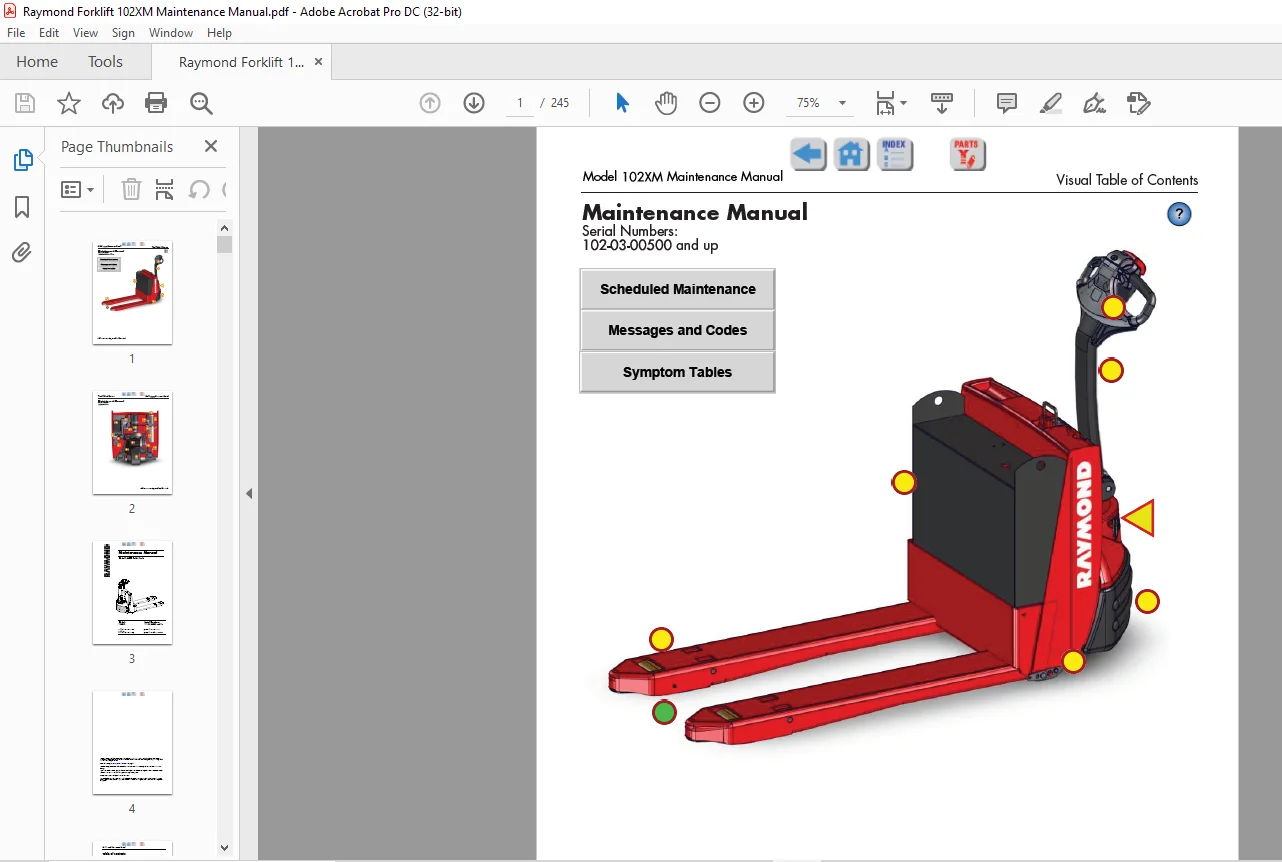
The Model 102XM Maintenance Manual is designed with the following objectives in mind:
• Provide technical coverage for expected levels of user expertise
• Anticipate your needs and reduce your decisions regarding maintenance
• Reduce page flipping through a “one-stop shopping” approach
The two-line running page header at the top of each page tells you the following:
• Name of the manual
(Model 102XM Maintenance Manual)
• Current chapter title
(example: this page How to Use This Manual)
• Current topic
(example: this page Manual Design)
This manual contains the following sections:
• Section 1. How to Use This Manual contains descriptive information about the manual in Manual Design and a reference table of Abbreviations & Symbols you may find throughout this manual.
• Section 2. Safety contains definitions of warning and caution notes, explains general safety rules and safety rules for battery safety, jacking safety, towing safety, static safety, and welding safety.
• Section 3. Systems Overview contains general information on truck specifications, operation, programming, and details for modes of operation.
• Section 4. Scheduled Maintenance outlines the recommended schedule of preventive services to keep your truck working most efficiently.
• Section 5. Troubleshooting is a set of general troubleshooting guidelines and a set of troubleshooting tables for symptoms not accompanied by a fault code. Once you are familiar with the symptoms listed, you may instead simply find the symptom in the “List of Troubleshooting Charts/Tables”.
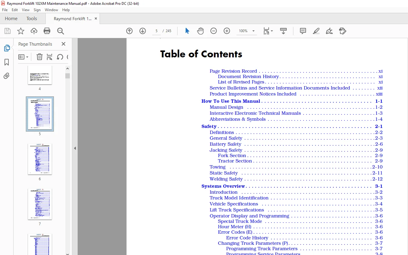
TABLE OF CONTENTS:
Raymond Forklift 102XM Pallet Truck Maintenance Manual SN 102-03-00500 and up – PDF DOWNLOAD
Page Revision Record xi
Document Revision History xi
List of Revised Pages xi
Service Bulletins and Service Information Documents Included xii
Product Improvement Notices Included xiii
How To Use This Manual 1-1
Manual Design 1-2
Interactive Electronic Technical Manuals 1-3
Abbreviations & Symbols 1-4
Safety 2-1
Definitions 2-2
General Safety 2-3
Battery Safety 2-6
Jacking Safety 2-9
Fork Section 2-9
Tractor Section 2-9
Towing 2-10
Static Safety 2-11
Welding Safety 2-12
Systems Overview 3-1
Introduction 3-2
Truck Model Identification 3-3
Vehicle Specifications 3-4
Lift Truck Specifications 3-5
Operator Display and Programming 3-6
Special Truck Mode 3-6
Hour Meter (H) 3-6
Error Codes (E) 3-6
Error Code History 3-6
Changing Truck Parameters (P) 3-7
Programming Truck Parameters 3-7
Programming Service Parameters 3-8
Parameter Displays 3-8
Setting Individual PIN-key Codes 3-9
Parameter Description 3-11
Parameter 1 3-11
Parameter 2 3-11
Parameter 3 3-11
Parameter 4 3-11
Parameter 5 3-11
Parameter 10 3-12
Parameter 14 3-12
Parameter 15
(starting with software version 3 6) 3-12
Parameter 16
(starting with software version 3 6) 3-12
Model 102XM Maintenance Manual
iv Publication:1010183, Issued: 20 Mar 2014
Parameter 20 3-12
Parameter 21 3-13
Parameter 25 3-13
Parameter 39 3-14
Display Part Numbers (Pn) 3-14
Service Display 3-15
Digital Inputs/Outputs from Power Amplifier 3-16
Power Amplifier Inputs 3-16
Power Amplifier Outputs 3-16
Digital Input from Vehicle Manager Control Sensors 3-17
Typical Power Amplifier Status 3-17
Special Tools 3-18
Programmable Maintenance Tool 3-19
Monitor Mode 3-20
Faults Mode 3-20
Information Mode 3-21
Programmer Mode 3-21
Service Key 3-22
TruckCom 3-23
General 3-23
Connection 3-23
Layout 3-24
Main Program Screen 3-24
Nodes 3-24
Icons 3-25
Tool Buttons and Menu Bar 3-25
Information Window 3-25
Status Bar 3-26
Connect Function 3-26
Disconnect Function 3-26
Downloading Program Function 3-27
Normal Downloading
(trucks with key) 3-27
Normal Downloading
(trucks with keypad) 3-27
Emergency Downloading 3-28
Emergency Downloading (trucks with key) 3-28
Emergency Downloading
(trucks with keypad) 3-28
Truck Report Function 3-28
Parameters Function 3-29
PIN Code 3-29
Hour Meters 3-30
Diagnostics Function 3-31
Representation of Signal Colors 3-31
Tiller Arm Tab 3-32
Drive Controller Tab 3-33
Other Menu Functions 3-34
Save to File 3-34
Download from File 3-34
Reset CAN Adapter 3-34
Delete Error Code Log 3-34
Model 102XM Maintenance Manual
Publication:1010183, Issued: 20 Mar 2014 v
Reset Hour Meter 3-34
Read Error Code Log 3-34
Help – About the TruckCom Application 3-34
Exit 3-34
FlashWare 3-35
Overview 3-35
Requirements 3-35
Installing FlashWare on PC 3-35
Connecting PC to Truck 3-35
Starting FlashWare 3-36
Scheduled Maintenance 4-1
Maintenance Guidelines 4-2
Initial 90 Day/250 Deadman Hours (HD) Maintenance 4-3
Every 180 Days or 500 Deadman Hours 4-4
Every 360 Days or 2000 Deadman Hours (HD) 4-6
Contactor Tip Inspection 4-7
Grease Fittings 4-8
Troubleshooting 5-1
List of Troubleshooting Charts and Tables 5-2
How to Use This Chapter 5-3
Electrical Troubleshooting Guidelines 5-4
General 5-4
Shorts to Frame 5-4
Shorts to Frame Test 5-5
DC Electric Motors 5-7
DC Motor Types 5-7
Inspection 5-7
Service 5-7
Open Circuit Motor Test 5-9
Grounded Motor Test 5-10
Short-Circuited Armature 5-10
Short-Circuited Winding 5-10
Hydraulic Troubleshooting Guidelines 5-11
List of Electrical Symbols 5-12
Symptom Table: Electrical System 5-13
BDI does not Reset to 100% 5-13
Horn Does Not Sound When Horn Button Pushed No Fault Codes 5-13
Green/Red LED on Keypad Not Illuminated When Key Pressed 5-14
Symptom Tables: Lift/Lower System 5-15
No Lift, Lift Motor Does Not
Run, Travel is OK 5-15
No Lift or Slow Lift, Lift Motor Does Run 5-16
No Lower, Lift and Travel OK 5-16
Unable to Pick Up a Load 5-17
Slow Lower 5-17
Load Drifting/Settling 5-17
No Lift or Lower No Fault Codes 5-18
Symptom Tables: Travel (Forward/Reverse) System 5-19
Slow Travel, Lift/Lower OK No Fault Codes 5-19
Truck Does Not Accelerate Correctly 5-19
Model 102XM Maintenance Manual
vi Publication:1010183, Issued: 20 Mar 2014
No Travel Mode No Fault Codes 5-20
Messages and Codes 6-1
List of Messages and Codes 6-2
Messages and Caution Codes 6-3
Code ‘TEST’ 6-3
Code ‘SLO’ 6-3
Code ‘Sro’ (C14) 6-3
Code C19 6-4
Code HPd (C20) 6-4
Code C28 6-5
Code C29 6-6
Code C35 6-6
Code Lo (C41) 6-6
Code Hi (C42) 6-7
Code C43 6-7
Code Hot1 (C44) 6-8
Code C46 6-8
Error Codes 6-9
Code E101 6-9
Code E104 6-9
Code E106 6-10
Code E107 6-10
Code E108 6-11
Code E110 6-11
Code E112 6-11
Code E114 6-12
Code E115 6-12
Code E118 6-13
Code E140 6-13
Code E141 6-13
Code E142 6-14
Code E150 6-14
Code E151 6-15
Code E157 6-15
Code E159 6-15
Code E160 6-16
Code E161 6-16
Code E200 6-17
Code E201 6-17
Code E202 6-17
Code E214 6-18
Component Procedures 7-1
List of Component Procedures by Component System 7-2
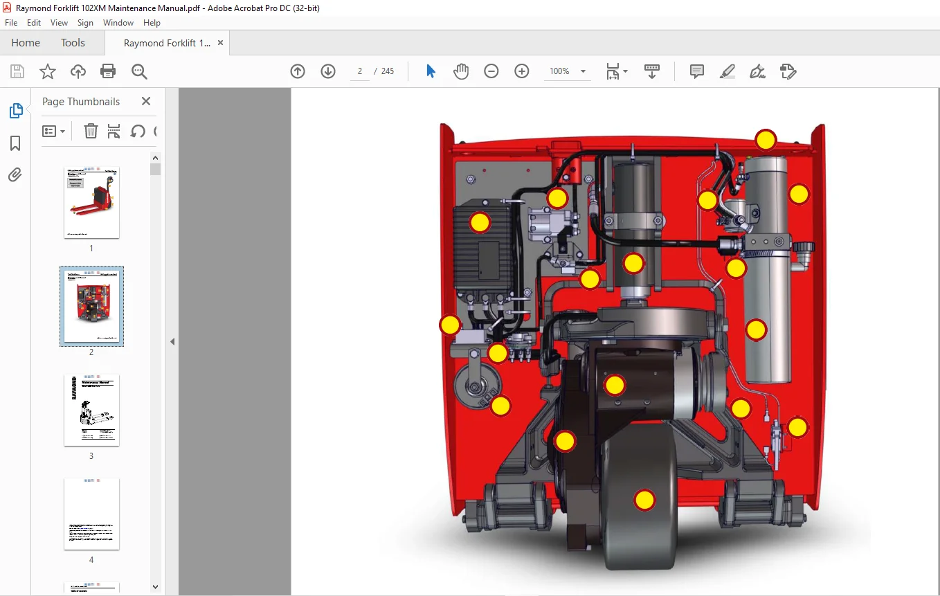
Component Locator Photos 7-5
Finish and Accessories 7-7
Tractor Covers 7-8
Tractor Cover Removal 7-8
Tractor Cover Installation 7-8
Tractor Bumper 7-9
Bumper Removal 7-9
Bumper Installation 7-9
Model 102XM Maintenance Manual
Publication:1010183, Issued: 20 Mar 2014 vii
Steering and Controls 7-11
Control Handle Head 7-12
Control Handle Disassembly 7-13
Horn Button/Switch Replacement 7-13
Lift/Lower Button Replacement 7-14
Push Button Replacement 7-14
Emergency Reverser Replacement 7-14
Control Handle Stem 7-16
Control Handle Stem Removal 7-16
Control Handle Stem Reassembly 7-17
Drive and Brake 7-19
Drive Unit Assembly 7-20
Electromagnetic Brake Assembly 7-20
Brake Disc Location 7-20
Air Gap Adjustment 7-20
Friction Disc Replacement 7-21
Mechanically Releasing the Brake 7-21
Electric Brake Release Kit Installation 7-22
Drive Wheel 7-23
Drive Wheel Removal 7-23
Tire Replacement 7-23
Drive Wheel Installation 7-24
Drive Unit 7-25
Drive Unit Removal 7-25
Drive Unit Disassembly 7-25
Drive Unit Assembly 7-26
Drive Unit Installation 7-28
Drive Unit Housing Lubrication 7-29
Gear Oil Level Check 7-29
Changing Gear Oil 7-29
Electrical Components 7-31
Battery 7-32
Swing-out Battery Pack 7-32
Removal (single battery) 7-32
Installation (single battery) 7-32
Removal (entire battery pack) 7-32
Installation (entire battery pack) 7-33
Maintenance-Free Batteries 7-33
Battery Maintenance 7-33
Battery Exterior Cleaning 7-33
Charging a Battery 7-34
Adding Water to a Battery 7-35
Battery Specific Gravity 7-35
Battery Voltage Check 7-36
Battery Storage 7-36
Power Cables 7-37
Power Cable Repair 7-37
Wiring Harness 7-39
Wiring Harness Terminology 7-39
Wiring Harness Inspection 7-39
Wiring Harness Repair 7-40
Model 102XM Maintenance Manual
viii Publication:1010183, Issued: 20 Mar 2014
Wiring Harness Soldering Procedures 7-40
Fuses 7-41
Fuse Test/Inspection 7-41
Circuit Breaker 7-42
Circuit Breaker Test/Inspection 7-42
Horn 7-43
Horn Removal 7-43
Horn Installation 7-43
Traction Power Amplifier 7-44
Cleaning the Traction Power Amplifier 7-44
Traction Power Amplifier Removal 7-44
Traction Power Amplifier Installation 7-44
Contactors 7-45
Main Contactor 7-45
Main Contactor Removal 7-45
Main Contactor Installation 7-45
Main Contactor, Sealed 7-45
Sealed Main Contactor Removal 7-45
Sealed Main Contactor Installation 7-46
Lift Motor Solenoid 7-46
Master Control Relay 7-47
Master Control Relay Inspection/Test 7-47
Switches (General) 7-48
Testing/Inspecting Switches 7-48
Main ON/OFF Switch 7-48
Main ON/OFF Switch Inspection 7-48
Main ON/OFF Switch Removal 7-48
Main ON/OFF Switch Installation 7-48
Arm Angle Switches 7-49
Arm Angle Switches Adjustment 7-49
Arm Angle Switches Removal 7-50
Arm Angle Switches Installation 7-50
Arm Angle Switches (Plastic Switch Bridge) 7-50
Lift-Limit Switch 7-53
Lift-Limit Switch Adjustment 7-53
Key Switch 7-53
Key Switch Inspection 7-53
Motors, General 7-54
Motor Brush Inspection 7-54
Motor Brush Replacement 7-54
Motor Brush Spring Tension 7-55
Brush Spring Tension Inspection 7-55
Terminal Nuts 7-56
Traction Motor 7-57
Brush Replacement 7-57
Motor Disassembly 7-57
Traction Motor Installation 7-57
Lift Motor 7-59
Lift Motor Removal 7-59
Lift Motor Installation 7-59
Lift Motor Brush Replacement 7-59
Model 102XM Maintenance Manual
Publication:1010183, Issued: 20 Mar 2014 ix
Hydraulic Components 7-61
Hydraulic Components 7-62
General Guidelines 7-62
Hydraulic Fluid 7-63
Hydraulic Fluid Level Check 7-63
Changing Hydraulic Fluid 7-63
Hydraulic Unit 7-64
Hydraulic Unit Removal 7-64
Hydraulic Unit Installation 7-64
Hydraulic Reservoir 7-65
Reservoir Removal 7-65
Reservoir Installation 7-65
Filter Screen and Inlet Tube 7-66
Filter Screen and Inlet Tube Removal 7-66
Filter Screen and Inlet Tube Installation 7-66
Hydraulic Pump 7-67
Hydraulic Pump Removal 7-67
Hydraulic Pump Installation 7-67
Hydraulic Pump Pressure Relief Valve Adjustment 7-68
Relief Valve Settings 7-68
Relief Valve Setting Check 7-68
Relief Valve Setting Adjustment 7-68
Hydraulic Cylinder 7-69
Cylinder Removal 7-69
Cylinder Disassembly 7-70
Cylinder Inspection 7-70
Cylinder Assembly 7-70
Cylinder Installation 7-70
Hydraulic Solenoid 7-72
Solenoid Removal 7-72
Solenoid Installation 7-72
Mast 7-73
Pallet Forks and Load Wheels 7-74
Load Wheels 7-74
Removal and Replacement 7-74
Load Wheel Pull Rod 7-74
Removal and Replacement 7-74
Carrier Frame Linkage 7-75
Downstops 7-76
Lower Link and Pivot Block Inspection 7-76
Downstop Adjustment 7-76
Skid Shoe Blocks 7-78
Skid Shoe Adjustment 7-78
Options 7-79
Cold Storage Conditioning 7-80
Cold Storage Hydraulic Fluid 7-80
Theory of Operation 8-1
Definitions 8-2
Acceleration 8-2
Arm Angle Switches 8-2
Click-to-Creep 8-2
Model 102XM Maintenance Manual
x Publication:1010183, Issued: 20 Mar 2014
Continuity 8-2
Controller Area Network (CAN) 8-2
Creep Speed 8-2
Current Limiting 8-2
Deceleration (Neutral Braking) 8-3
Emergency Reverse 8-3
Fault Codes 8-3
High Pedal Disable (HPD) 8-3
Open Circuit 8-3
Overvoltage Cutoff 8-3
PIN-Key Code 8-3
Pulse Width Modulation 8-3
Regenerative Braking 8-3
Short Circuit or “Short” 8-3
Speed Limiting 8-4
Static Return to Off (SRO) 8-4
Thermal Cutback (Traction Power Amplifier) 8-4
Tractor 8-4
Truck Off Delay (Keypad only) 8-4
Undervoltage Cutoff 8-4
Vehicle Manager 8-4
Truck Starting 8-5
Traction System 8-6
Vehicle Manager 8-6
Power Amplifier 8-6
Direction/Speed Control 8-6
Control Handle Positioning 8-6
Travel Request 8-6
Emergency Reverse 8-7
Electric Brake Release Switch 8-7
Lift/Lower System 8-8
Lift 8-8
Lower 8-8
Appendix A-1
Lubrication Equivalency Chart A-2
Thread Adhesives, Sealants, and Lubricants A-3
Component Specific Service/Torque Chart A-4
Torque Chart – Standard (Ferrous) A-6
Torque Chart – Standard (Brass) A-7
Torque Chart – Metric (Ferrous) A-8
Torque Chart – Metric (Brass) A-9
Torque Chart – Thread-Forming Screws A-9
Torque Chart – Hydraulic Fittings A-10
Torque Chart – Straight Thread Face Seal O-Rings A-11
Decimal Equivalent Chart A-12
Standard/Metric Conversions A-14
Index I-1
IMAGES PREVIEW OF THE MANUAL:
Need help? Contact: [email protected]
https://vimeo.com/836417232?share=copy
PLEASE NOTE:
- This is the SAME manual used by the dealers to troubleshoot any faults in your vehicle. This can be yours in 2 minutes after the payment is made.
- Contact us at [email protected] should you have any queries before your purchase or that you need any other service / repair / parts operators manual.
S.V