Raymond Forklift 21 TRACTOR SCR & RESISTOR PARTS CATALOG MANUAL – PDF DOWNLOAD
$25.95
Raymond Forklift 21 TRACTOR SCR & RESISTOR PARTS CATALOG MANUAL – PDF DOWNLOAD
Description
Raymond Forklift 21 TRACTOR SCR & RESISTOR PARTS CATALOG MANUAL – PDF DOWNLOAD
FILE DETAILS:
Raymond Forklift 21 TRACTOR SCR & RESISTOR PARTS CATALOG MANUAL – PDF DOWNLOAD
Language : English
Pages :194
Downloadable : Yes
File Type : PDF
Size:33.9 MB
DESCRIPTION:
Introduction
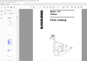
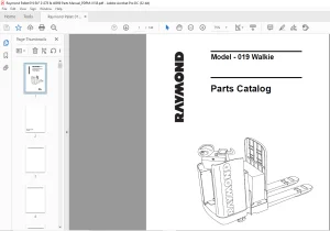
Introduction to Your Parts Catalog The Raymond Corporation manufactures a variety of lift trucks in both standard and customized configurations. The Parts Catalog is organized into major divisions which cover oil areas of the truck. These may include:
• Power Unit [if applicable) • Hydraulic (if applicable)
• Broke end Steering • Elevating/ Attachments
• Drive Unit • Contadors
• Eledriccl • Special Options (if applicable)
Using the Catalog
The catalog contains three elements necessary for effective use, which ore:
Raymond Forklift 21 TRACTOR SCR & RESISTOR PARTS CATALOG MANUAL – PDF DOWNLOAD
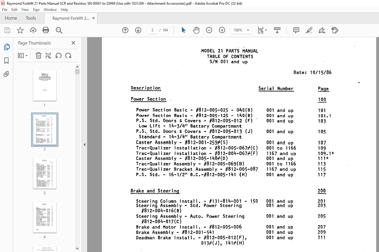
TABLE OF CONTENTS:
Raymond Forklift 21 TRACTOR SCR & RESISTOR PARTS CATALOG MANUAL – PDF DOWNLOAD
Power Section Basic – #812-005-025 – 040(6)
Power Section Basic – #812-005-125 – 140(B)
P.S. Std.’ Doors & Covers – #812-005-012 (F)
Low Lift – 14-3/411 Battery Compartment
P.S. Std. Doors & Covers – #812-005-013 (J)
. Sta.ndard – 14-3/411 Battery Compartment
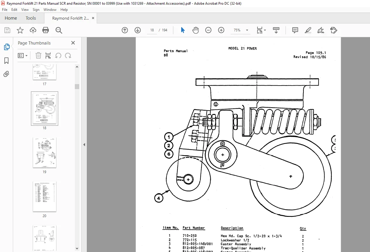
Caster Assembly – #812-001-259f(S)
Trac-Qualizer Installation – #812-005-067+(C)
Trac-Qualizer Installation – #812-004-067f(F)
Caster Assembly – #812-005-148f(D)
Trac-Qualizer Assembly – #812-005-069(6)
Trac-Qualizer Bracket Assembly – #812-005-087
P.S. Std. – 16-1/211 B.C.-#812-005-141 (H)
Brake and Steering
Steering Column Install. – #131-814-001 –
Steering Assembly – Std. Power Steering
#812-004-016(8)
Steering Assembly – Auto. Power Steering
#812-004-017(C)
Brake and Motor Install. – #812-005-006
Brake Assembly – #812-001-541
Deadman Brake Install. – #812-005-012(F),
013,'(J), 141,'(H)
Drive Unit
Drive Unit Assembly – #812-005-007f(C)
Gear Housing – #812-001-230
Drive Wheel Assembly – #812-001-840,'(C)
Drive Motor – #570-44o+100
Electrical
Electrical Symbols
Schematic – #812-005-017(8)
150
Wiring Diagram – #812-005-016(6) – Sheet 1 ·
Wiring Diagram – #812-005-016(B) – Sheet 2
Systems Electrical – #812-005-015(J)- Sheet
Systems Electrical – #812-005-015(J)- Sheet 2
Systems Electrical – #154-008-422f(C) Remote
Controller Assembly – #154-002-500f
Control Elec. – Mod II SCR – #154-008-518f(D)
Panel Assembly – #812-005-018
Panel Assembly – #812-008-404f(F)
Panel Assembly – #154-007-205f
Description
Electrical (Cont’d.)
MODEL 21 PARTS MANUAL
TABLE OF CONTENTS
S/N 001 and up
Heat Sink Assembly – #154-008-406,’Heter
Installation – #812-004-146
Panel Assembly – #812-004-146 (C)
Battery Connector Install. – #154-005-039 (A)
Battery Connector Assembly – #812-000-144
Low Voltage Circuit Breaker Assembly
& Installation – #154-008-4131′- (A)
Curtis Fuel Gauge Install. – #812-005-0llr
Meter Installation – #154-008-421
Limit Switch I nsta 11 at ion – 20″ ·, 24″
Hi-Speed Cutout – #821-001-238-f
Limit Switch Installation – High Speed
Clear Height – #812-001-270,f
Limit Switch Install.- High Speed Clear Height
#154-007-2407′-
Lift Limit Switch Assembly – #787-003-060,’Control
Unit Assembly – #154-005-350
Warning Light Installation – #154-005-638
Working Light Installation
Cord Reel Installation – #812-004-1761’Cord
Reel Switch Install. – #812-002-752
Electrical Supp. Switching Solenoid –
#812-001-926 (E)
Conversion Kit Installation – #812-004-0431′-(C)
Contactor – P – #1-105-056f100
Contactor – M – #1-105-014
Contactor – X – #1-105-018
Contactor – F & R – #1-105-032
Contactor – PC – #1-105-079
Hydraulic
Hydraulic Symbols
Schematic – Low Lift – #812-004-133
Schematic – Standard – #812-004-134(A)
Hydraulic Systems – Low Lift – #812-005-063
Hydraulic Systems Reach W/Aux. Function-14-3/411
Battery Compartment – #812-004-167(L)-Sh.1
Hydraulic Systems W/0 Aux. Function – 14-3/411
Battery Compartment – #812•004-167(L)-Sheet 2
Hydraulic Systems Reach W/Aux. Function-16-1/211
Battery Compartment – #812-005•144+(F)
Hydraulic Systems W/0 Aux. Function – 16-1/V’
Battery Compartment – #812-005•144f{F)
Hydraulic Systems – Straddle w/Aux. Functions
14-3/411 Batt. Compt. – #812-004•237f003 {B)
Hydraulic Systems – Straddle w/Aux. Functions
16-1/211 Batt. Compt. – #812-003-238 {B)
Hydraulic (Cont’d.)
Valve Assembly – Low Lift- #812-005-062 001 and up
Solenoid Valve Assembly – Low Lift – #520-432 001 and up
Valve Lock Assembly – Low Lift – #520~307 001 and up
Auxilfary Control Piping – #812-002-lOOf and 001 and up
#812-002-099f
Reservoir Assembly – #812-004-024 001 and up
Lift Motor – #570-217f100 001 and up
Lift Motor – #570-2171-200 001 and up
Lift Pump – #500-423 001 and up
Lift Pump & Motor Assembly – #812-005-009(0) 001 and up
Auxiliary Pump – #500-417f200 001 and up
Auxiliary Pump – #500-417+201 001 and up
Auxiliary Pump – #500-417f100 001 and up
Auxiliary Motor – #570-442f100 001 and up
Auxiliary Pump and Motor Installation – 001 and up
#812-005-010
Motor Steer Assy. – #812-002-623(F) 001 and up
Auxiliary Valve lnst.-1 Spool-812-002-169~RIE1~ 001 and up
Auxiliary Valve lnst.-2 Spool-812-002-170 RIEl 001 and up
Auxiliary Valve lnst.-3 Spool-812-002-171(RIE1) 001 and up
Control Valve Assy. – Lift – #812-004-141(C) 001 and up
Control Valve – #520-065 001 to 1149
Control Valve – #520-075 1150 and up
Control Valve – #520-066 001 to 1149
Control Valve – #520-076 1150 and up
Control Valve – #520-053 001 to 1149
Control Valve – #520-077 1150 and up
Piping – Tractor to Attach. – #812-000-492 001 and up
Piping – Tractor to Attach. – #761-151-089 001 and up
Hydraulic Supp. – #812-001-896 001 and up
Switching Solenoid Install. – #812-001-920f and 001 and up
#812-001-91 lf
Manifold Assembly – #812-004-166f(D) 001
Lift/Lower Manifold – #520-825f001, 002(8) 001
Lift Valve Install. – #812-005-013f(J), 141,'(H) 001
Valve Assembly – 2 Spool – #812-001-956 001
Valve Assembly – 3 Spool – #812-001-957 001
Hydraulic Ram Feed Line lnstal. – #812-005-061f 001
IMAGES PREVIEW OF THE MANUAL:
Questions? Email us: [email protected]
PLEASE NOTE:
- This is the same manual used by the DEALERSHIPS to SERVICE your vehicle.
- The manual can be all yours – Once payment is complete, you will be taken to the download page from where you can download the manual. All in 2-5 minutes time!!
- Need any other service / repair / parts manual, please feel free to contact us at heydownloadss @gmail.com . We may surprise you with a nice offer
S.M