Trusted Business
Verified & Licensed
Virus Free Files
100% Safe Downloads
Secure Payment
SSL Protected
Instant Delivery
Available Immediately
Raymond Forklift 7400 7420 7440 Reach-Fork® Truck With The ACR System™ Parts Manual 1107605 – PDF DOWNLOAD
$36.95
Raymond Forklift 7400 7420 7440 Reach-Fork® Truck With The ACR System™ Parts Manual 1107605 – PDF DOWNLOAD
Instant PDF Download
Available immediately
Save to Your Device
Download & keep forever
Antivirus Scanned
100% virus-free
Trusted Worldwide
175,000+ customers
Description
Raymond Forklift 7400 7420 7440 Reach-Fork® Truck With The ACR System™ Parts Manual 1107605 – PDF DOWNLOAD
FILE DETAILS:
Raymond Forklift 7400 7420 7440 Reach-Fork® Truck With The ACR System™ Parts Manual 1107605 – PDF DOWNLOAD
Language : English
Pages :963
Downloadable : Yes
File Type : PDF
Size:104 MB
TABLE OF CONTENTS:
Raymond Forklift 7400 7420 7440 Reach-Fork® Truck With The ACR System™ Parts Manual 1107605 – PDF DOWNLOAD
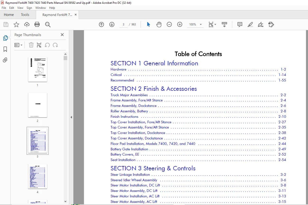
SECTION 1 General Information
Hardware 1-2
Critical 1-14
Recommended 1-55
SECTION 2 Finish & Accessories
Truck Major Assemblies 2-2
Frame Assembly, Fore/Aft Stance 2-4
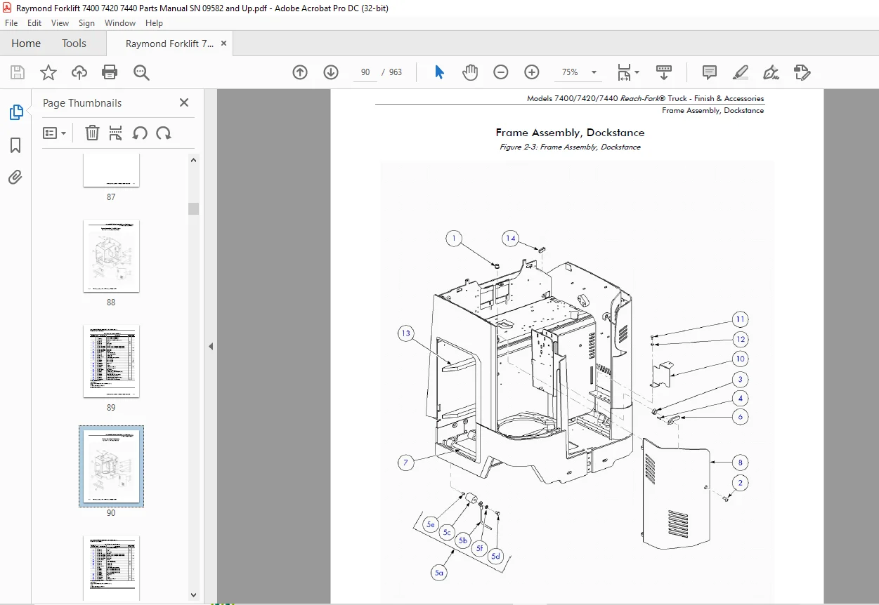
Frame Assembly, Dockstance 2-6
Roller Assembly, Battery 2-8
Finish Instructions 2-10
Top Cover Installation, Fore/Aft Stance 2-27
Top Cover Assembly, Fore/Aft Stance 2-35
Top Cover Installation, Dockstance 2-38
Top Cover Assembly, Dockstance 2-42
Floor Pad Installation, Models 7400, 7420, and 7440 2-44
Battery Gate Installation 2-49
Battery Covers, EE 2-52
Seat Installation 2-54
SECTION 3 Steering & Controls
Steer Linkage Installation 3-2
Steered Idler Wheel Assembly 3-6
Steer Motor Installation, DC Lift 3-8
Steer Motor Assembly, DC Lift 3-11
Steer Motor Installation, AC Lift 3-13
Steer Motor Assembly, AC Lift 3-15
Steering Wheel Installation, Fore/Aft Stance, DC Lift 3-17
Steering Wheel Installation, Fore/Aft Stance, AC Lift 3-20
Steering Wheel Assembly, Fore/Aft Stance, AC Lift 3-23
Steering Wheel Installation, Dockstance, DC Lift 3-26
Steering Wheel Installation, Dockstance, AC Lift 3-28
Control Handle Installation, Fore/Aft Stance, Primary 3-32
Control Handle Assembly, Fore/Aft Stance, Primary 3-34
Control Handle Assembly, Fore/Aft Stance, Primary, ThermaKit 3-39
Control Handle Installation, Dockstance 3-43
Control Handle Assembly, Dockstance 3-45
Control Handle Assembly, Dockstance, Thermakit 3-50
Control Handle Installation, Fore/Aft Stance, Secondary 3-54
Control Handle Assembly, Fore/Aft Stance, Secondary 3-56
Control Handle Assembly, Fore/Aft Stance, Secondary, ThermaKit 3-58
Bracket Handle, Weldment 3-61
Tiller Installation 3-63
SECTION 4 Drive & Brake
Drive Unit Installation 4-2
Drive Motor Installation 4-4
Drive Unit Assembly 4-6
Brake Installation, Electric 4-9
Brake Assembly, Electric 4-11
Deadman Pedal Installation, Fore/Aft Stance 4-13
Deadman Pedal Assembly, Fore/Aft Stance 4-16
Deadman Pedal Installation, Dockstance 4-20
Deadman Pedal Assembly, Dockstance 4-23
Drive Wheel Installation 4-27
Inertial Dampener Assembly 4-29
Deadman Pedal Assembly 4-31
SECTION 5 Electrical Comp. & System
Electrical System, Fore/Aft Stance, AC Lift 5-2
Electrical System, Fore/Aft Stance, DC Lift 5-9
Electrical System, Dockstance, AC Lift 5-15
Electrical System, Dockstance, DC Lift 5-23
Traction Power Amplifier Installation 5-28
Traction Power Amplifier Installation 5-31
Lift Power Amplifier Installation 5-33
Vehicle Manager Installation 5-35
Vehicle Manager Installation 5-37
Contactor Panel Installation, DC Lift (AC/DC) 5-39
Contactor Panel Installation, AC Lift 5-44
Contactor Assembly 5-49
Drive Motor, AC (Danaher TSW) 5-51
Drive Motor, AC, UL Class E 5-54
Drive Motor AC 5-56
Lift Motor, DC 5-58
Lift Motor, AC 5-60
Auxiliary Motor, DC Only 5-63
Operator Display Installation, Fore/Aft Stance 5-65
Operator Display Installation, Dockstance, DC Lift 5-67
Operator Display Installation, Dockstance, AC Lift 5-69
Horn Installation 5-71
Switch Assembly, Key 5-74
Relay/Control Fuse Panel Installation With Auxiliary Power 5-76
Battery Connector Installation 5-79
Connector Installation-Euro 5-81
Battery Connector Assembly 5-83
Battery Connector Assembly 5-85
Battery Connector Assembly-Pigtail (Euro) 5-87
Battery Connector Assembly 5-89
Encoder Installation, Height Indicator, Model 7400 5-91
Guard-Height Sensing Installation 5-96
Encoder Installation, Height Indicator, Models 7420 and 7440 5-98
Encoder Assembly, Height Indicator, Model 7400 5-103
Encoder Assembly, Height Indicator, Models 7420 and 7440 5-105
Ambient Temperature Sensor Installation 5-107
Fan Assembly, Drive Motor Compartment 5-109
Fan Assembly, Lift Motor Compartment 5-111
Speed Limiting Switch (S12) 5-113
Speed Limiting Switch (S12) Installation (Proximity), Models 7420 and 7440 5-117
SECTION 6 Hydraulic Components
Hose Installation, Fore/Aft Stance, AC Lift Motor (Model 7400 EH < 331 in.) 6-2
Hose Installation, Fore/Aft Stance, AC Lift Motor (Model 7400 EH > 330 in., and all
Models 7420 and 7440) 6-4
Hose Installation W/ Flow Regulator 6-6
Hose Installation, Fore/Aft Stance, DC Lift Motor 6-8
Hose Installation, Dockstance, AC Lift Motor, No Auxiliary Reservoir 6-11
Hose Installation, Dockstance, AC Lift Motor, With Auxiliary Reservoir 6-13
Hose Installation, Dockstance, DC Lift Motor 6-15
Reservoir Assembly 6-17
Lift Pump and Motor Assembly, DC 6-20
Lift Pump and Motor Assembly, AC 6-25
Auxiliary Pump and Motor Installation 6-27
Auxiliary Pump and Motor Assembly 6-30
Lift Pump, DC, Single 6-32
Lift Pump, DC, Dual 6-34
Lift Pump, AC 6-36
Auxiliary Pump 6-38
Main Manifold Installation, AC Lift 6-40
Main Manifold Assembly, AC Lift, Model 7400 6-42
Main Manifold Assembly, AC Lift, Models 7420 and 7440 6-46
Main Manifold Installation, DC Lift Motor 6-50
Main Manifold Assembly, DC Lift 6-52
Auxiliary Manifold Assembly, Single Reach 6-56
Manifold Assembly, Reach, DR32TT 6-58
Manifold Assembly, Tilt, DR32TT 6-60
Manifold Assembly, Tilt and Sideshift, DR32TT 6-62
Cylinder Assembly, Main Lift 6-64
Main Lift Cylinder, Models 7420 and 7440 6-67
Cylinder, Free Lift, Non-Staging (DC Lift), Model 7400 R35TT 6-69
Cylinder, Free Lift, Staging, Model 7400, R45TT, DR32TT 6-71
Cylinder, Free Lift, Staging (AC Lift), Model 7420 and 7440, R45TT, DR32TT 6-74
Cylinder, Free Lift, Staging (AC Lift), Models 7420 and 7440, R45TT, DR32TT (ALL) 6-76
Cylinder Assembly, Reach 6-78
Cylinder Assembly, Reach 6-80
Cylinder, Tilt 6-82
Cylinder, Tilt 6-84
Cylinder Assembly, Sideshift 6-86
Cylinder Assembly, Sideshift 6-88
SECTION 7 Mast
Mast to Tractor Mounting, Model 7400 7-3
Mast to Tractor Mounting, Models 7420 and 7440 7-5
Elevating Section, R35TT 7-7
Elevating Section, R45TT and DR32TT (Model 7400) 7-18
Elevating Section, R45TT and DR32TT (Model 7420) 7-26
Elevating Section, R45TT and DR32TT (Model 7440) 7-35
Chain, Free Lift, Assembly, Model 7400 7-44
Chain, Free Lift, Models 7420 and 7440 7-55
Chain, Main Lift, Assembly 7-60
Cylinder and Pulley Bracket Assembly, Free Lift, Model 7400 7-72
Cylinder and Pulley Bracket Assembly, Free Lift, Models 7420 and 7440 7-76
Overhead Guard Installation 7-78
Overhead Guard, Installation, Shim Spacer 7-80
Overhead Guard-Drive in Rack 7-82
Hose and Cable Installation, Mast, Model 7400 7-84
Hose and Cable Installation, Mast, Model 7420 7-101
Hose and Cable Installation, Mast, Model 7440 7-112
Carriage Installation, R35TT and R45TT 7-124
Reach Carriage Assembly, R35TT and R45TT 7-127
Scissor Assembly, R35TT and R45TT 7-133
Carriage Installation, DR32TT 7-135
Reach Carriage Assembly, DR32TT 7-138
Scissors Assembly-DRTT 7-143
Hose and Cable Installation, Carriage, R35TT and R45TT 7-148
Hose and Cable Installation, Carriage, DR32TT 7-152
Carriage Assembly, Tilt without Integral Sideshift, R35TT and R45TT 7-155
Carriage Assembly, Tilt and Sideshift, R35TT and R45TT 7-157
Carriage Subassembly, Tilt and Sideshift, R35TT and R45TT 7-159
Carriage Assembly, Tilt without Sideshift, DR32TT 7-161
Carriage Assembly, Tilt and Sideshift, DR32TT 7-163
Carriage Subassembly, Sideshift, DR32TT 7-165
Carriage Assembly, Side Shift, Bolzoni 7-167
Mast Guard Installation, Mesh 7-169
Mast Guard Installation, Glass 7-171
Baseleg Installation, R35TT, 5 x 3.62 in., Open Toe 7-173
Baseleg Installation, R35TT, 5 x 3.62 in., Straddle Closed Toe 7-175
Baseleg Installation, R35TT, 5 x 2.88 in., Open Toe 7-177
Baseleg Installation, R35TT, 5 x 2.88 in., Straddle Closed Toe 7-179
Baseleg Installation, R35TT, 4 x 3.62 in., Closed Toe 7-181
Baseleg Installation, R35TT, 4 x 2.88 in., Closed Toe 7-183
Baseleg Installation, R45TT, 5 x 3.62 in., Open Toe 7-185
Baseleg Installation, R45TT, 5 x 3.62 in., Closed Toe 7-187
Baseleg Installation, R45TT, 5 x 2.88 in., Open Toe 7-189
Baseleg Installation, R45TT, 5 x 2.88 in., Closed Toe 7-191
Baseleg Installation, R45TT, 4 x 3.62 in., Closed Toe 7-193
Baseleg Installation, R45TT, 4 x 2.88 in., Closed Toe 7-195
Baseleg Installation, DR32TT, 5 x 3.62 in., Closed Toe 7-197
Baseleg Installation, DR32TT, 5 x 2.88 in., Closed Toe 7-199
Baseleg Installation, DR32TT, 4 x 3.62 in., Closed Toe 7-201
Baseleg Installation, DR32TT, 4 x 2.88 in., Closed Toe 7-203
Baseleg Installation, R45TT, 6 x 4 in., Open Toe (Models 7420 and 7440) 7-205
Baseleg Installation, R45TT, 6 x 4 in., Closed Toe (Models 7420 and 7440) 7-207
Baseleg Installation, DR32TT, R45TT 5 x 3.62 in., Closed Toe (Models 7420 and 7440) 7-209
Wheel Plate Installation, Open Toe, 5 x 3.62 in. 7-211
Wheel Plate Installation, 6 x 4 in., Open Toe (Models 7420 and 7440) 7-213
Wheel Plate Installation, 10.5 x 4.5 in., Open Toe (Model 7400 R45TT) 7-215
Wheel Plate Installation, Closed Toe, Cast (All Except 6 x 4 in.) 7-218
Wheel Plate Installation, Closed Toe, Cast (6 x 4 in.) 7-221
Wheel Plate Installation, OWCTWB, 5 x 3.62 in. and 5 x 2.88 in. 7-223
Load Wheel Assembly 7-225
Stop Assembly 7-228
Sideshift Stop Assembly 7-230
Stop Assembly, Carriage 7-232
Forks 7-234
SECTION 8 Options & Kits
Load Backrest Installation 8-2
Rear Door Installation, Fore/Aft Stance 8-4
Rear Door Installation, Dockstance 8-6
Fire Extinguisher Installation 8-8
Rear Post, Guard, Fore/Aft Stance 8-10
Rear Post, Guard, Dockstance 8-12
Rapid Charge Battery Connector Installation 8-14
Rapid Charge Battery Connector Assembly 8-16
Nested Switch (S14) Installation, Standard Reach 8-18
Nested Switch (S14) Installation, Deep-Reach 8-20
Vantage Point System 8-23
Security Start Switch 8-43
Height-Tilt Indicator Display Installation 8-45
R.F. Installation 8-47
RF Adjustable Linkage Installation 8-52
Operator Compartment Sensor System (OCSS), Fore/Aft Stance 8-55
Hardware 1-2
Critical 1-14
Recommended 1-55
SECTION 2 Finish & Accessories
Truck Major Assemblies 2-2
Frame Assembly, Fore/Aft Stance 2-4
Frame Assembly, Dockstance 2-6
Roller Assembly, Battery 2-8
Finish Instructions 2-10
Top Cover Installation, Fore/Aft Stance 2-27
Top Cover Assembly, Fore/Aft Stance 2-35
Top Cover Installation, Dockstance 2-38
Top Cover Assembly, Dockstance 2-42
Floor Pad Installation, Models 7400, 7420, and 7440 2-44
Battery Gate Installation 2-49
Battery Covers, EE 2-52
Seat Installation 2-54
SECTION 3 Steering & Controls
Steer Linkage Installation 3-2
Steered Idler Wheel Assembly 3-6
Steer Motor Installation, DC Lift 3-8
Steer Motor Assembly, DC Lift 3-11
Steer Motor Installation, AC Lift 3-13
Steer Motor Assembly, AC Lift 3-15
Steering Wheel Installation, Fore/Aft Stance, DC Lift 3-17
Steering Wheel Installation, Fore/Aft Stance, AC Lift 3-20
Steering Wheel Assembly, Fore/Aft Stance, AC Lift 3-23
Steering Wheel Installation, Dockstance, DC Lift 3-26
Steering Wheel Installation, Dockstance, AC Lift 3-28
Control Handle Installation, Fore/Aft Stance, Primary 3-32
Control Handle Assembly, Fore/Aft Stance, Primary 3-34
Control Handle Assembly, Fore/Aft Stance, Primary, ThermaKit 3-39
Control Handle Installation, Dockstance 3-43
Control Handle Assembly, Dockstance 3-45
Control Handle Assembly, Dockstance, Thermakit 3-50
Control Handle Installation, Fore/Aft Stance, Secondary 3-54
Control Handle Assembly, Fore/Aft Stance, Secondary 3-56
Control Handle Assembly, Fore/Aft Stance, Secondary, ThermaKit 3-58
Bracket Handle, Weldment 3-61
Tiller Installation 3-63
SECTION 4 Drive & Brake
Drive Unit Installation 4-2
Drive Motor Installation 4-4
Drive Unit Assembly 4-6
Brake Installation, Electric 4-9
Brake Assembly, Electric 4-11
Deadman Pedal Installation, Fore/Aft Stance 4-13
Deadman Pedal Assembly, Fore/Aft Stance 4-16
Deadman Pedal Installation, Dockstance 4-20
Deadman Pedal Assembly, Dockstance 4-23
Drive Wheel Installation 4-27
Inertial Dampener Assembly 4-29
Deadman Pedal Assembly 4-31
SECTION 5 Electrical Comp. & System
Electrical System, Fore/Aft Stance, AC Lift 5-2
Electrical System, Fore/Aft Stance, DC Lift 5-9
Electrical System, Dockstance, AC Lift 5-15
Electrical System, Dockstance, DC Lift 5-23
Traction Power Amplifier Installation 5-28
Traction Power Amplifier Installation 5-31
Lift Power Amplifier Installation 5-33
Vehicle Manager Installation 5-35
Vehicle Manager Installation 5-37
Contactor Panel Installation, DC Lift (AC/DC) 5-39
Contactor Panel Installation, AC Lift 5-44
Contactor Assembly 5-49
Drive Motor, AC (Danaher TSW) 5-51
Drive Motor, AC, UL Class E 5-54
Drive Motor AC 5-56
Lift Motor, DC 5-58
Lift Motor, AC 5-60
Auxiliary Motor, DC Only 5-63
Operator Display Installation, Fore/Aft Stance 5-65
Operator Display Installation, Dockstance, DC Lift 5-67
Operator Display Installation, Dockstance, AC Lift 5-69
Horn Installation 5-71
Switch Assembly, Key 5-74
Relay/Control Fuse Panel Installation With Auxiliary Power 5-76
Battery Connector Installation 5-79
Connector Installation-Euro 5-81
Battery Connector Assembly 5-83
Battery Connector Assembly 5-85
Battery Connector Assembly-Pigtail (Euro) 5-87
Battery Connector Assembly 5-89
Encoder Installation, Height Indicator, Model 7400 5-91
Guard-Height Sensing Installation 5-96
Encoder Installation, Height Indicator, Models 7420 and 7440 5-98
Encoder Assembly, Height Indicator, Model 7400 5-103
Encoder Assembly, Height Indicator, Models 7420 and 7440 5-105
Ambient Temperature Sensor Installation 5-107
Fan Assembly, Drive Motor Compartment 5-109
Fan Assembly, Lift Motor Compartment 5-111
Speed Limiting Switch (S12) 5-113
Speed Limiting Switch (S12) Installation (Proximity), Models 7420 and 7440 5-117
SECTION 6 Hydraulic Components
Hose Installation, Fore/Aft Stance, AC Lift Motor (Model 7400 EH < 331 in.) 6-2
Hose Installation, Fore/Aft Stance, AC Lift Motor (Model 7400 EH > 330 in., and all
Models 7420 and 7440) 6-4
Hose Installation W/ Flow Regulator 6-6
Hose Installation, Fore/Aft Stance, DC Lift Motor 6-8
Hose Installation, Dockstance, AC Lift Motor, No Auxiliary Reservoir 6-11
Hose Installation, Dockstance, AC Lift Motor, With Auxiliary Reservoir 6-13
Hose Installation, Dockstance, DC Lift Motor 6-15
Reservoir Assembly 6-17
Lift Pump and Motor Assembly, DC 6-20
Lift Pump and Motor Assembly, AC 6-25
Auxiliary Pump and Motor Installation 6-27
Auxiliary Pump and Motor Assembly 6-30
Lift Pump, DC, Single 6-32
Lift Pump, DC, Dual 6-34
Lift Pump, AC 6-36
Auxiliary Pump 6-38
Main Manifold Installation, AC Lift 6-40
Main Manifold Assembly, AC Lift, Model 7400 6-42
Main Manifold Assembly, AC Lift, Models 7420 and 7440 6-46
Main Manifold Installation, DC Lift Motor 6-50
Main Manifold Assembly, DC Lift 6-52
Auxiliary Manifold Assembly, Single Reach 6-56
Manifold Assembly, Reach, DR32TT 6-58
Manifold Assembly, Tilt, DR32TT 6-60
Manifold Assembly, Tilt and Sideshift, DR32TT 6-62
Cylinder Assembly, Main Lift 6-64
Main Lift Cylinder, Models 7420 and 7440 6-67
Cylinder, Free Lift, Non-Staging (DC Lift), Model 7400 R35TT 6-69
Cylinder, Free Lift, Staging, Model 7400, R45TT, DR32TT 6-71
Cylinder, Free Lift, Staging (AC Lift), Model 7420 and 7440, R45TT, DR32TT 6-74
Cylinder, Free Lift, Staging (AC Lift), Models 7420 and 7440, R45TT, DR32TT (ALL) 6-76
Cylinder Assembly, Reach 6-78
Cylinder Assembly, Reach 6-80
Cylinder, Tilt 6-82
Cylinder, Tilt 6-84
Cylinder Assembly, Sideshift 6-86
Cylinder Assembly, Sideshift 6-88
SECTION 7 Mast
Mast to Tractor Mounting, Model 7400 7-3
Mast to Tractor Mounting, Models 7420 and 7440 7-5
Elevating Section, R35TT 7-7
Elevating Section, R45TT and DR32TT (Model 7400) 7-18
Elevating Section, R45TT and DR32TT (Model 7420) 7-26
Elevating Section, R45TT and DR32TT (Model 7440) 7-35
Chain, Free Lift, Assembly, Model 7400 7-44
Chain, Free Lift, Models 7420 and 7440 7-55
Chain, Main Lift, Assembly 7-60
Cylinder and Pulley Bracket Assembly, Free Lift, Model 7400 7-72
Cylinder and Pulley Bracket Assembly, Free Lift, Models 7420 and 7440 7-76
Overhead Guard Installation 7-78
Overhead Guard, Installation, Shim Spacer 7-80
Overhead Guard-Drive in Rack 7-82
Hose and Cable Installation, Mast, Model 7400 7-84
Hose and Cable Installation, Mast, Model 7420 7-101
Hose and Cable Installation, Mast, Model 7440 7-112
Carriage Installation, R35TT and R45TT 7-124
Reach Carriage Assembly, R35TT and R45TT 7-127
Scissor Assembly, R35TT and R45TT 7-133
Carriage Installation, DR32TT 7-135
Reach Carriage Assembly, DR32TT 7-138
Scissors Assembly-DRTT 7-143
Hose and Cable Installation, Carriage, R35TT and R45TT 7-148
Hose and Cable Installation, Carriage, DR32TT 7-152
Carriage Assembly, Tilt without Integral Sideshift, R35TT and R45TT 7-155
Carriage Assembly, Tilt and Sideshift, R35TT and R45TT 7-157
Carriage Subassembly, Tilt and Sideshift, R35TT and R45TT 7-159
Carriage Assembly, Tilt without Sideshift, DR32TT 7-161
Carriage Assembly, Tilt and Sideshift, DR32TT 7-163
Carriage Subassembly, Sideshift, DR32TT 7-165
Carriage Assembly, Side Shift, Bolzoni 7-167
Mast Guard Installation, Mesh 7-169
Mast Guard Installation, Glass 7-171
Baseleg Installation, R35TT, 5 x 3.62 in., Open Toe 7-173
Baseleg Installation, R35TT, 5 x 3.62 in., Straddle Closed Toe 7-175
Baseleg Installation, R35TT, 5 x 2.88 in., Open Toe 7-177
Baseleg Installation, R35TT, 5 x 2.88 in., Straddle Closed Toe 7-179
Baseleg Installation, R35TT, 4 x 3.62 in., Closed Toe 7-181
Baseleg Installation, R35TT, 4 x 2.88 in., Closed Toe 7-183
Baseleg Installation, R45TT, 5 x 3.62 in., Open Toe 7-185
Baseleg Installation, R45TT, 5 x 3.62 in., Closed Toe 7-187
Baseleg Installation, R45TT, 5 x 2.88 in., Open Toe 7-189
Baseleg Installation, R45TT, 5 x 2.88 in., Closed Toe 7-191
Baseleg Installation, R45TT, 4 x 3.62 in., Closed Toe 7-193
Baseleg Installation, R45TT, 4 x 2.88 in., Closed Toe 7-195
Baseleg Installation, DR32TT, 5 x 3.62 in., Closed Toe 7-197
Baseleg Installation, DR32TT, 5 x 2.88 in., Closed Toe 7-199
Baseleg Installation, DR32TT, 4 x 3.62 in., Closed Toe 7-201
Baseleg Installation, DR32TT, 4 x 2.88 in., Closed Toe 7-203
Baseleg Installation, R45TT, 6 x 4 in., Open Toe (Models 7420 and 7440) 7-205
Baseleg Installation, R45TT, 6 x 4 in., Closed Toe (Models 7420 and 7440) 7-207
Baseleg Installation, DR32TT, R45TT 5 x 3.62 in., Closed Toe (Models 7420 and 7440) 7-209
Wheel Plate Installation, Open Toe, 5 x 3.62 in. 7-211
Wheel Plate Installation, 6 x 4 in., Open Toe (Models 7420 and 7440) 7-213
Wheel Plate Installation, 10.5 x 4.5 in., Open Toe (Model 7400 R45TT) 7-215
Wheel Plate Installation, Closed Toe, Cast (All Except 6 x 4 in.) 7-218
Wheel Plate Installation, Closed Toe, Cast (6 x 4 in.) 7-221
Wheel Plate Installation, OWCTWB, 5 x 3.62 in. and 5 x 2.88 in. 7-223
Load Wheel Assembly 7-225
Stop Assembly 7-228
Sideshift Stop Assembly 7-230
Stop Assembly, Carriage 7-232
Forks 7-234
SECTION 8 Options & Kits
Load Backrest Installation 8-2
Rear Door Installation, Fore/Aft Stance 8-4
Rear Door Installation, Dockstance 8-6
Fire Extinguisher Installation 8-8
Rear Post, Guard, Fore/Aft Stance 8-10
Rear Post, Guard, Dockstance 8-12
Rapid Charge Battery Connector Installation 8-14
Rapid Charge Battery Connector Assembly 8-16
Nested Switch (S14) Installation, Standard Reach 8-18
Nested Switch (S14) Installation, Deep-Reach 8-20
Vantage Point System 8-23
Security Start Switch 8-43
Height-Tilt Indicator Display Installation 8-45
R.F. Installation 8-47
RF Adjustable Linkage Installation 8-52
Operator Compartment Sensor System (OCSS), Fore/Aft Stance 8-55
Operator Compartment Sensor System (OCSS), Dockstance 8-58
High Performance Air Flow (DC Lift) 8-61
Travel Light and Alarm Installation 8-63
Working Light and Operator Cooling Fan Harness Installation 8-69
Working Light and Operator Cooling Fan Installation 8-73
Fan Assembly, Operator 8-75
Auxiliary Light, Warning, Harness Installation 8-77
Strobe Light Installation 8-79
Auxiliary Light, Flashing-Warning, Installation 8-82
Light, Warning, Strobe Lamp Assembly 8-85
Light Assembly, Warning, Flashing 8-87
Tilt Carriage Shims 8-89
Fork-Laser System Installation 8-92
Battery Gate Alarm Installation 8-98
Overhead Guard Covers 8-100
Manifold, Remote Grease, Installation 8-102
Wear Plates, Mainframe (Short Plates) 8-104
Wear Plates, Mainframe (Long Plates) 8-106
Broom Holder 8-108
Alarm-Free Lift 8-110
APPENDIX A Alphabetical Parts Index
APPENDIX B Numerical Parts Index
IMAGES PREVIEW OF THE MANUAL:
Customer Support: [email protected]
https://vimeo.com/837948776?share=copy
PLEASE NOTE:
- This is the same manual used by the dealers to diagnose and troubleshoot your vehicle
- You will be directed to the download page as soon as the purchase is completed. The whole payment and downloading process will take anywhere between 2-5 minutes
- Need any other service / repair / parts manual, please feel free to contact [email protected] . We still have 50,000 manuals unlisted
s.m