Raymond Forklift 760076207640 Reach-Fork® Truck With The ACR System™ Parts Manual 1087945A – PDF DOWNLOAD
$28.95
Raymond Forklift 760076207640 Reach-Fork® Truck With The ACR System™ Parts Manual 1087945A – PDF DOWNLOAD
Description
Raymond Forklift 760076207640 Reach-Fork® Truck With The ACR System™ Parts Manual 1087945A – PDF DOWNLOAD
FILE DETAILS:
Raymond Forklift 760076207640 Reach-Fork® Truck With The ACR System™ Parts Manual 1087945A – PDF DOWNLOAD
Language : English
Pages :488
Downloadable : Yes
File Type : PDF
Size:64.5 MB
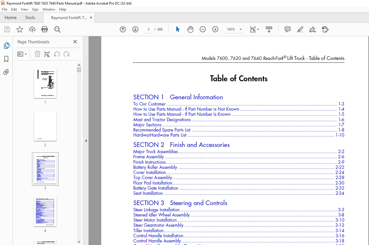
TABLE OF CONTENTS:
Raymond Forklift 760076207640 Reach-Fork® Truck With The ACR System™ Parts Manual 1087945A – PDF DOWNLOAD
SECTION 1 General Information
To Our Customer 1-3
How to Use Parts Manual – If Part Number is Not Known 1-4
How to Use Parts Manual – If Part Number Is Known 1-5
Mast and Tractor Designations 1-6
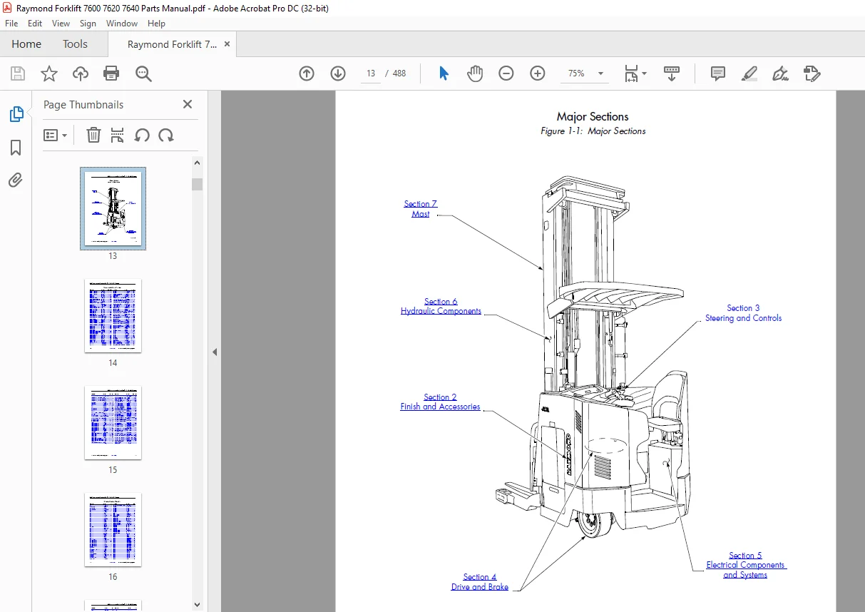
Major Sections 1-7
Recommended Spare Parts List 1-8
HardwarHardware Parts List 1-10
SECTION 2 Finish and Accessories
Major Truck Assemblies 2-2
Frame Assembly 2-6
Finish Instructions 2-9
Battery Roller Assembly 2-22
Cover Installation 2-24
Top Cover Assembly 2-28
Floor Pad Installation 2-30
Battery Gate Installation 2-32
Seat Installation 2-34
SECTION 3 Steering and Controls
Steer Linkage Installation 3-3
Steered Idler Wheel Assembly 3-8
Steer Motor Installation 3-10
Steer Gearmotor Assembly 3-12
Tiller Installation 3-14
Control Handle Installation 3-16
Control Handle Assembly 3-18
Control Handle Assembly, ThermaKit 3-22
ThermaKit Control Installation 3-26
SECTION 4 Drive and Brake
Drive Unit Installation 4-2
Drive Motor Installation 4-4
Drive Unit Assembly 4-6
Electric Brake Installation 4-10
Electric Brake Assembly 4-13
Deadman Pedal Assembly 4-15
Drive Wheel Assembly 4-19
Inertial Dampener Assembly 4-20
SECTION 5 Electrical Components and Systems
Electrical System 5-2
Traction Power Amplifier Installation 5-8
Lift Power Amplifier Installation 5-10
Vehicle Manager Installation 5-11
Contactor Panel Installation 5-12
Models 7600, 7620 and 7640 Reach-Fork® Lift Truck – Table of Contents
ii Publication: 1087945, Issued: 03/27/2009
Contactor Assembly 5-16
Drive Motor 5-18
Lift Motor, AC (Sauer Danfoss) 5-20
Operator Display Installation 5-22
Horn Installation 5-25
Key Switch Assembly 5-29
Relay/Control Fuse Panel Installation with Auxiliary Power 5-30
Battery Connector Installation 5-33
Battery Connector Assembly 5-34
Height Encoder Installation (Model 7600) 5-36
Height Encoder Installation (Models 7620 and 7640) 5-41
Encoder Assembly, Height Indicator (Model 7600) 5-47
Encoder Assembly, Height Indicator (Models 7620 and 7640) 5-48
Ambient Temperature Sensor Installation 5-50
Fan Assembly, Drive Motor Compartment 5-52
Fan Assembly, Lift Motor Compartment 5-53
Speed Limiting Switch (S12) Installation (Proximity) (Model 7600) 5-55
Speed Limiting Switch (S12) Installation (Proximity) (Models 7620 and 7640) 5-58
SECTION 6 Hydraulic Components
Hose Installation (Model 7600) 6-2
Hose Installation (Models 7620 and 7640) 6-4
Reservoir Assembly 6-6
Lift Pump and Motor Assembly, AC 6-8
Lift Pump 6-10
Main Manifold Installation 6-11
Main Manifold Assembly (Model 7600) 6-13
Main Manifold Assembly (Models 7620 and 7640) 6-17
Auxiliary Manifold Assembly, Single Reach 6-20
Manifold Assembly, Reach, DR32TT 6-22
Manifold Assembly, Tilt, DR32TT 6-24
Manifold Assembly, Tilt and Sideshift, DR32TT 6-25
Main Lift Cylinder (Model 7600) 6-26
Main Lift Cylinder (Models 7620 and 7640) 6-28
Cylinder, Free Lift, Staging (Model 7600) 6-30
Cylinder, Free Lift, Staging (Models 7620 and 7640) R45TT/DR32TT 6-32
Cylinder Assembly, Reach 6-34
Cylinder Assembly, Tilt 6-36
Cylinder Assembly, Sideshift 6-38
SECTION 7 Mast
Mast to Tractor Mounting (Model 7600) 7-2
Mast to Tractor Mounting (Models 7620 and 7640) 7-3
Elevating Section, R45TT and DR32TT (Model 7600) 7-5
Elevating Section, R45TT and DR32TT (Model 7620) 7-15
Elevating Section, R45TT and DR32TT (Model 7640) 7-23
Free Lift Chain Assembly (Model 7600) 7-31
Free Lift Chain Assembly (Models 7620 and 7640) 7-34
Cylinder and Pulley Bracket Assembly, Free Lift (Model 7600) 7-36
Cylinder and Pulley Bracket Assembly, Free Lift (Models 7620 and 7640) 7-38
Overhead Guard Installation 7-40
Hose and Cable Installation, Mast (Model 7600) 7-41
Hose and Cable Installation, Mast (Model 7620) 7-52
Hose and Cable Installation, Mast (Model 7640) 7-63
Carriage Installation (R45TT) 7-76
Reach Carriage Assembly (R45TT) 7-79
Scissor Arm Assembly (R45TT) 7-84
Carriage Installation (DR32TT) 7-87
Reach Carriage Assembly (DR32TT) 7-90
Scissor Arm Assembly, Deep-Reach® (DR32TT) 7-94
Hose and Cable Installation, Carriage (R45TT) 7-98
Hose and Cable Installation, Carriage (DR32TT) 7-103
Carriage Assembly, Tilt Only (R45TT) 7-106
Carriage Subassembly, Tilt and Sideshift (R45TT) 7-108
Carriage Subassembly, Tilt and Sideshift (R45TT) 7-111
Carriage Assembly, Tilt Only, No Sideshift (DR32TT) 7-112
Carriage Assembly, Tilt and Sideshift (DR32TT) 7-114
Carriage Assembly, Sideshift (DR32TT) 7-117
Mast Guard Installation, Mesh 7-118
Mast Guard Installation, Glass 7-120
Baseleg Installation, R45TT, 5 x 3 62 in , Open Toe 7-122
Baseleg Installation, R45TT, 5 x 3 62 in , Closed Toe 7-124
Baseleg Installation, R45TT, 5 x 2 88 in , Closed Toe 7-126
Baseleg Installation, R45TT, 4 x 3 62 in , Closed Toe 7-128
Baseleg Installation, R45TT, 4 x 2 88 in , Closed Toe 7-130
Baseleg Installation, DR32TT, 5 x 3 62 in , Closed Toe 7-132
Baseleg Installation, 5 x 2 88 in , Closed Toe 7-134
Baseleg Installation, 4 x 3 62 in , Closed Toe 7-136
Baseleg Installation, DR32TT, 4 x 2 88 in , Closed Toe 7-138
Baseleg Installation, R45TT, 6 x 4 in , Open Toe (Models 7620 and 7640) 7-140
Baseleg Installation, R45TT, 6 x 4 in , Closed Toe (Models 7620 and 7640) 7-141
Baseleg Installation, DR32TT, 5 x 3 62 in , Closed Toe (Models 7620 and 7640) 7-142
Wheel Plate Installation, Open Toe, 5 x 3 62 in 7-143
Wheel Plate Installation, Open Toe, 6 x 4 in (Models 7620 and 7640) 7-144
Wheel Plate Installation, Open Toe, 10 5 x 4 5 in (Model 7600, R45TT) 7-146
Wheel Plate Installation, Closed Toe, Cast (All Except 6 x 4 in ) 7-148
Wheel Plate Installation, Closed Toe, Cast (6 x 4 in ) 7-152
Wheel Plate Installation, OWCTWB, 5 x 3 62 in and 5 x 2 88 in 7-154
Load Wheel Assembly 7-156
Stop Assembly 7-158
Forks 7-159
SECTION 8 Options/Kits
Load Backrest Installation 8-2
Rear Post Installation 8-4
Overhead Guard Covers 8-6
Fire Extinguisher Installation 8-8
Rapid Charge Battery Connector Installation 8-9
Nested Switch (S14) Installation, Standard Reach 8-10
Nested Switch (S14) Installation, Deep-Reach 8-12
Vantage Point System 8-14
Height Tilt Indicator Display Installation 8-30
R F Installation 8-33
Travel Light and Alarm Installation 8-39
Models 7600, 7620 and 7640 Reach-Fork® Lift Truck – Table of Contents
iv Publication: 1087945, Issued: 03/27/2009
Working Light(s) and Operator Cooling Fan Harness Installation 8-45
Working Light(s) and Operator Cooling Fan Installation 8-48
Fan Assembly, Operator 8-50
Warning Light Harness Installation 8-52
Strobe Light Installation 8-55
Flashing Light Installation 8-59
Light, Warning, Strobe Lamp Assembly 8-62
Light Assembly, Warning, Flashing 8-64
Tilt Carriage Shims 8-65
Motion Sensor Installation 8-69
Battery Gate Alarm Installation 8-73
Fork Laser Sensor Installation 8-77
APPENDIX A Alphabetical Parts Index
APPENDIX B Numerical Parts Index
IMAGES PREVIEW OF THE MANUAL:
https://vimeo.com/837956417?share=copy
Customer Support: [email protected]
PLEASE NOTE:
- This is the same manual used by the dealers to diagnose and troubleshoot your vehicle
- You will be directed to the download page as soon as the purchase is completed. The whole payment and downloading process will take anywhere between 2-5 minutes
- Need any other service / repair / parts manual, please feel free to contact [email protected] . We still have 50,000 manuals unlisted
s.m