Raymond Forklift 8210 & 8250 Pallet Trucks Maintenance Manual 146945-001D – PDF DOWNLOAD
$28.95
Raymond Forklift 8210 & 8250 Pallet Trucks Maintenance Manual 146945-001D – PDF DOWNLOAD
Description
Raymond Forklift 8210 & 8250 Pallet Trucks Maintenance Manual 146945-001D – PDF DOWNLOAD
FILE DETAILS:
Raymond Forklift 8210 & 8250 Pallet Trucks Maintenance Manual 146945-001D – PDF DOWNLOAD
Language : English
Pages : 321
Downloadable : Yes
File Type : PDF
DESCRIPTION:
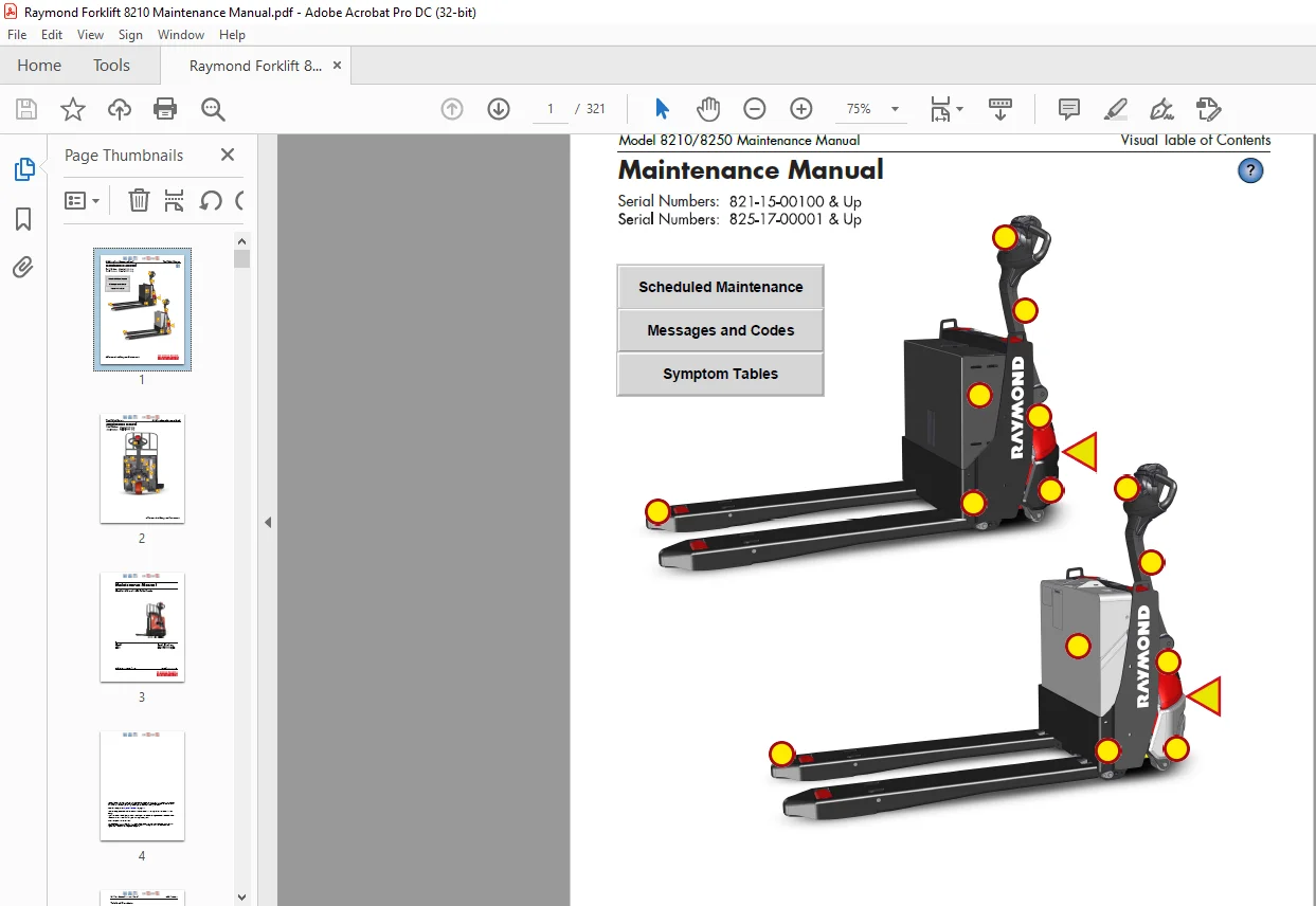
Raymond Forklift 8210 & 8250 Pallet Trucks Maintenance Manual 146945-001D – PDF DOWNLOAD
Page Revision Record:
• Technical changes – These changes are identified by a vertical line (change bar) in the left margin next to the change. Pages affected by technical changes are identified with “Revised: Month Year” in the footer. These pages may also be available on the Raymond Portal.
IMAGES PREVIEW OF THE MANUAL:
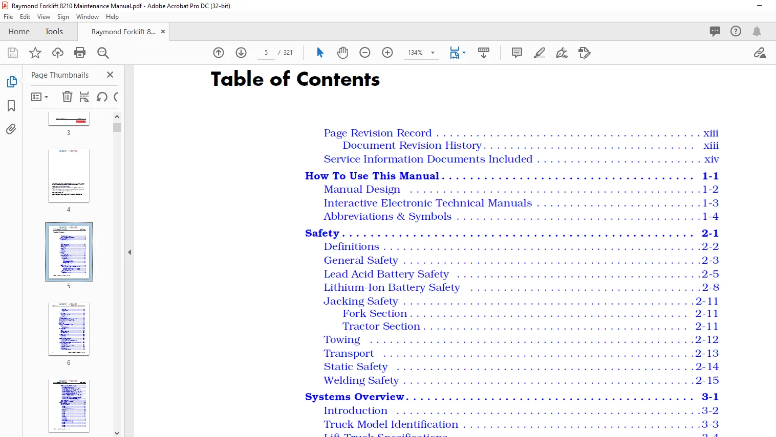
TABLE OF CONTENTS:
Raymond Forklift 8210 & 8250 Pallet Trucks Maintenance Manual 146945-001D – PDF DOWNLOAD
Page Revision Record xiii
Document Revision History xiii
Service Information Documents Included xiv
How To Use This Manual 1-1
Manual Design 1-2
Interactive Electronic Technical Manuals 1-3
Abbreviations & Symbols 1-4
Safety 2-1
Definitions 2-2
General Safety 2-3
Lead Acid Battery Safety 2-5
Lithium-Ion Battery Safety 2-8
Jacking Safety 2-11
Fork Section 2-11
Tractor Section 2-11
Towing 2-12
Transport 2-13
Static Safety 2-14
Welding Safety 2-15
Systems Overview 3-1
Introduction 3-2
Truck Model Identification 3-3
Lift Truck Specifications 3-4
Operator Display and Programming 3-5
Special Truck Mode 3-5
Hour Meter (H) 3-6
Error Codes (E) 3-6
Error Code History 3-6
Changing Truck Parameters (P) 3-6
Programming Truck Parameters 3-6
Programming Service Parameters 3-8
Parameter Displays 3-8
Setting Individual PIN-key Codes 3-8
Display Part Numbers (Pn) 3-16
Display Test (d) 3-16
Service Display 3-17
Digital Inputs/Outputs from Traction Amplifier and VM 3-17
Traction Amplifier Inputs 3-18
Traction Amplifier Outputs 3-18
Digital Input from Vehicle Manager Control Sensors 3-19
Digital Input from Vehicle Manager Control Sensors 3-19
Typical Power Amplifier Status 3-20
Special Tools 3-21
Service Key 3-21
Programmable Maintenance Tool 3-21
Table of Contents Model 8210/8250 Maintenance Manual
ii Publication:1146945/001, Revised: 25 Sep 2018
Monitor Mode 3-22
Faults Mode 3-23
Information Mode 3-23
Programmer Mode 3-23
FlashWare 3-25
Overview 3-25
Requirements 3-25
Installing FlashWare on PC 3-25
Connecting PC to Truck 3-25
Starting FlashWare 3-25
Scheduled Maintenance 4-1
Maintenance Guidelines 4-2
Initial 90 Day/250 Deadman Hours (HD) Maintenance 4-3
Every 180 Days or 500 Deadman Hours (HD) 4-4
Every 360 Days or 2000 Deadman Hours (HD) 4-6
Grease Fittings 4-7
Pin Locations 4-8
Troubleshooting 5-1
List of Troubleshooting Charts and Tables 5-2
Electrical Troubleshooting Guidelines 5-5
General 5-5
Shorts to Frame 5-5
Shorts to Frame Test 5-6
DC Electric Motors 5-8
DC Motor Types 5-8
Inspection 5-8
Service 5-9
Open Circuit Motor Test 5-12
Grounded Motor Test 5-12
Short-Circuited Armature 5-12
Short-Circuited Winding 5-13
AC Electric Motors 5-14
AC Motor Type 5-14
Open Winding 5-14
Shorted Winding 5-14
Hydraulic Troubleshooting Guidelines 5-15
Symptom Table: Electrical System 5-16
BDI Does Not Reset to 100% 5-16
Horn Does Not Sound When Horn Button Pushed
No Fault Codes 5-16
Green/Red LED on Keypad Not Illuminated When Key Pressed 5-17
Symptom Tables: Lift/Lower System 5-18
No Lift, Lift Motor Does Not
Run, Travel is OK 5-18
No Lift or Slow Lift, Lift Motor Does Run 5-19
No Lower, Lift and Travel OK 5-19
Unable to Pick Up a Load 5-20
Slow Lower 5-20
Load Drifting/Settling 5-20
No Lift or Lower No Fault Codes 5-21
Model 8210/8250 Maintenance Manual Table of Contents
Publication:1146945/001, Revised: 25 Sep 2018 iii
Symptom Tables: Travel (Forward/Reverse) System 5-22
Slow Travel, Lift/Lower OK No Fault Codes 5-22
Truck Does Not Accelerate Correctly 5-22
No Travel Mode No Fault Codes 5-23
No Travel or Slow Travel TA Flash Code 2,2, (Thermal
Cutback) Heatsink Temperature Exceeded 185°F (85°C)
Operator Display May Indicate Hot2 (C45) 5-23
No Travel, No Lift/Lower TA Flash Code 3,1 Operator Display
May Indicate Error Code E106 5-23
No Travel, Main Contactor Does Not Close TA Flash Code 3,9
Operator Display Indicates Error Code E107 5-23
No Travel, No Lift/Lower TA Flash Code 1,3 Operator Display
Indicates Error Code E202 5-24
No Travel, No Lift/Lower TA Flash Code 1,2 Operator Display
Indicates Error Code E201 5-24
No Truck Functions Active TA Flash Code 1,7, (Low Battery
Voltage) Operator Display May Indicate E221 5-24
No Truck Functions Active TA Flash Code 1,8, (Excessive
Battery Voltage) Operator Display May Indicate E222 5-24
Charger Troubleshooting 5-25
Lithium-ion Battery Troubleshooting 5-26
Messages and Codes 6-1
List of Messages and Codes 6-2
Messages and Caution Codes 6-5
Code ‘GATE’ 6-5
Code ‘TEST’ 6-5
Code ‘SLO’ 6-5
Code ‘Sro’ (C14) 6-6
Code ‘LoGn’ (C15) (iWAREHOUSE® Only) 6-6
Code br_o (C16) 6-6
Code C19 6-7
Code HPd (C20) 6-7
Code C26 6-7
Code C27 6-8
Code C30 6-8
Code C31 6-8
Code C32 6-9
Code C33 6-9
Code C35 6-9
Code Lo (C41) 6-10
Code Hi (C42) 6-10
Code Cold (C43) 6-11
Code Hot1 (C44) 6-11
Code Hot2 (C45) 6-12
Code C46 (iWAREHOUSE® Only) 6-12
Code C47 (iWAREHOUSE® Only) 6-12
Code C48 6-13
Code C57 6-13
Code C60 6-13
Code C61 6-14
Code C62 6-14
Code C64 6-14
Code C66 6-15
Code C67 6-15
Code C68 6-15
Code C70 6-16
Code C71 6-16
Code C72 6-16
Code 075 6-17
Code AC (C256) 6-17
Code C257 6-17
Code C258 6-17
Code C259 6-18
Code C380 6-18
Code C382 6-18
Code C383 6-19
Code C384 6-19
Code C385 6-19
Code C395 6-20
Code C405 6-20
Error Codes 6-21
Code E101 6-21
Code E106 6-21
Code E107 6-22
Code E108 6-22
Code E109 6-22
Code E140 6-23
Code E141 6-23
Code E142 6-23
Code E150 6-24
Code E151 6-24
Code E152 6-24
Code E157 6-25
Code E159 6-25
Code E160 6-25
Code E201 6-26
Code E202 6-26
Code E203 6-26
Code E220 6-27
Code E221 6-27
Code E222 6-27
Code E223 6-28
Code E224 6-28
Code E225 6-28
Code E228 6-29
Code E230 6-29
Code E232 6-29
Code E233 6-30
Code E235 6-30
Code E236 6-30
Code E248 6-31
Code E249 6-31
Code E250 6-31
Code E251 6-32
Code E254 6-32
Code E690 6-32
Code E691 6-33
Code E700 6-33
Code E901 6-33
Code E996 6-34
Code E997 6-34
Code E998 6-34
Code E999 6-35
Code BTLR 6-35
8250 Messages and Caution Codes 6-36
Code AC 6-36
Code b_Lo (C500) 6-36
Code bYE (C360) 6-36
Code C501 6-37
Code C502 6-37
Code C503 6-37
Code C504 6-38
Code C505 6-38
Code C506 6-38
Code C507 6-39
Code Hot3 (C508) 6-39
Code Cold (C509) 6-39
Code C510 6-40
Code C511 6-40
Code C512 6-40
Code C513 6-41
Code C514 6-41
Code C515 6-41
Code C516 6-42
Code C517 6-42
Code C518 6-42
Code C519 6-43
Code E751 6-43
Traction Amplifier Flash Codes 6-44
Delta-Q Charger Codes 6-46
Component Procedures 7-1
List of Component Procedures by Component System 7-2
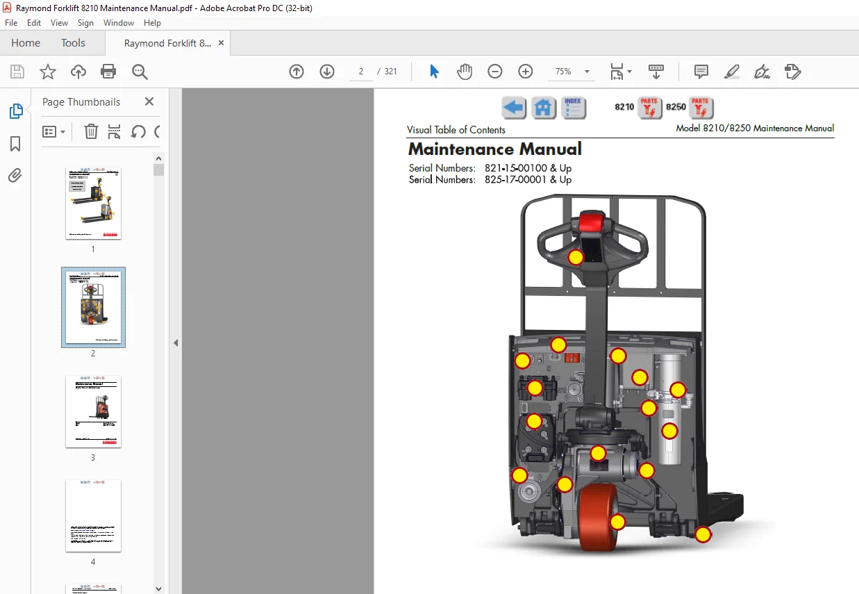
Component Location Photos 7-5
Finish and Accessories 7-7
Tractor Covers 7-8
Tractor Cover Removal 7-8
Lower Cover Removal 7-8
Grille Cover Removal 7-9
Upper Cover Removal 7-9
Console Cover Removal 7-9
Tractor Cover Installation 7-10
Console Cover Installation 7-10
Upper Cover Installation 7-10
Grille Cover Installation 7-11
Lower Cover Installation 7-11
Table of Contents Model 8210/8250 Maintenance Manual
vi Publication:1146945/001, Revised: 25 Sep 2018
Tractor Bumper 7-13
Bumper Removal 7-13
Bumper Installation 7-13
Steering and Controls 7-15
Control Handle Head 7-16
Control Handle Disassembly 7-17
Horn Button/Switch Replacement 7-18
Lift/Lower Button Replacement 7-18
Push Button Replacement 7-18
Emergency Reverse Replacement 7-19
Keypad 7-20
Keypad Removal 7-20
Keypad Installation 7-21
Control Arm Assembly 7-23
Control Arm Removal 7-24
Control Arm Installation 7-24
Drive and Brake 7-27
Drive Unit Assembly 7-28
Drive Unit 7-30
Drive Unit Removal 7-30
Drive Unit Disassembly 7-31
Drive Unit Assembly 7-31
Drive Unit Installation 7-32
Drive Unit Housing Lubrication 7-33
Gear Oil Level Check 7-33
Changing Gear Oil 7-33
Drive Wheel 7-34
Drive Wheel Removal 7-34
Tire Replacement 7-34
Drive Wheel Installation 7-35
Electromagnetic Brake Assembly 7-36
Brake Disc Location 7-36
Air Gap Inspection 7-36
Friction Disc Replacement 7-36
Electric Brake Release 7-37
Mechanical Brake Release 7-37
Electrical Components 7-39
Lead Acid Battery 7-40
Swing-out Battery Pack 7-40
Removal (entire battery pack) 7-40
Installation (entire battery pack) 7-41
Removal (single battery) 7-41
Installation (single battery) 7-41
Charger Replacement 7-42
Battery Maintenance 7-43
Battery Exterior Cleaning 7-43
To Charge a Battery 7-44
To Charge a Raymond Battery Pack (Option) 7-45
To Add Water to a Battery 7-45
Battery Specific Gravity 7-46
Specific Gravity Check 7-46
Model 8210/8250 Maintenance Manual Table of Contents
Publication:1146945/001, Revised: 25 Sep 2018 vii
Battery Voltage Check 7-46
Battery Storage 7-46
Lithium-Ion Battery 7-47
Battery Removal 7-48
Battery Installation 7-48
Lithium-Ion Battery Covers 7-49
General Information 7-49
Top Cover 7-49
Top Cover Removal 7-49
Top Cover Installation 7-49
Front Cover 7-50
Front Cover Removal 7-50
Front Cover Installation 7-50
Cell Module Assembly, Battery Monitoring Unit, and
Cell Module Assembly Fuse 7-51
Cell Module Assembly, Battery Monitoring Unit, and
Cell Module Assembly Fuse Removal 7-51
Cell Module Assembly, Battery Monitoring Unit, and
Cell Module Assembly Fuse Installation 7-52
Battery Management Controller 7-54
BMC Removal 7-54
BMC Installation 7-55
BMC Fuse 7-56
BMC Fuse Removal 7-56
BMC Fuse Installation 7-56
Charger 7-56
Charger Removal 7-56
Charger Installation 7-57
Charger Cord 7-57
Charge Cord Removal 7-57
Charge Cord Installation 7-57
Lithium-ion Battery User Interface (HUD) 7-58
Lithium-ion Battery Display Removal 7-58
Lithium-ion Battery Display Installation 7-58
Wire Harness 7-58
Wire Harness Removal 7-58
Wire Harness Installation 7-59
Counterweight 7-60
Counterweight Removal 7-60
Counterweight Installation 7-60
Cooling Fan 7-61
Cooling Fan Removal 7-61
Cooling Fan Installation 7-61
SBX Cable Assembly 7-61
SBX Cable Assembly Removal 7-61
SBX Cable Assembly Installation 7-62
Specification and Warning Labels 7-63
Label Removal 7-63
Label Installation 7-63
Battery Connector 7-64
Inspection 7-64
Battery Connector Access and Removal 7-64
Table of Contents Model 8210/8250 Maintenance Manual
viii Publication:1146945/001, Revised: 25 Sep 2018
Cable Removal, Replacement, and Installation 7-65
Power Cables 7-66
Power Cable Repair 7-66
Wiring Harness 7-68
Wiring Harness Terminology 7-68
Wiring Harness Inspection 7-68
Wiring Harness Repair 7-69
Wiring Harness Soldering Procedures 7-69
Main Harness Bracket Removal 7-70
Main Harness Installation 7-70
Fuses 7-72
Fuse Test/Inspection 7-72
Horn 7-73
Horn Removal 7-73
Horn Installation 7-73
Traction Amplifier 7-74
To Clean the Traction Amplifier 7-74
Traction Amplifier Removal 7-74
Traction Amplifier Installation 7-74
Contactors 7-76
Resistance Testing 7-76
Contactor Removal 7-76
Contactor Installation 7-76
Lift Motor Solenoid 7-78
Switches (General) 7-79
Testing/Inspecting Switches 7-79
Main ON/OFF Switch 7-79
Main ON/OFF Switch Inspection 7-79
Main ON/OFF Switch Removal 7-79
Main ON/OFF Switch Installation 7-79
2-Position Keyed Switch (Optional) 7-80
Replacement 7-80
Arm Angle Proximity Switch 7-80
Replacement 7-80
Arm Angle Proximity Switch Adjustment 7-81
Lift Cutout Proximity Switch 7-82
Replacement 7-82
DC Motors, General 7-83
Motor Brush Inspection 7-83
Motor Brush Replacement 7-83
Motor Brush Spring Tension 7-84
Brush Spring Tension Inspection 7-84
Terminal Nuts 7-85
Polishing the Commutator 7-85
Traction Motor 7-86
Traction Motor Disassembly 7-88
Traction Motor Assembly 7-88
Speed Sensor (Encoder) Replacement 7-89
Terminal Block Replacement 7-90
Model 8210/8250 Maintenance Manual Table of Contents
Publication: 1146945/001, Revised: 25 Sep 2018 ix
Lift Motor 7-91
Lift Motor Removal 7-91
Lift Motor Installation 7-91
Lift Motor Brush Replacement 7-91
Hydraulic Components 7-92
Hydraulic Components 7-93
General Guidelines 7-93
Hydraulic Unit Torque Specifications 7-93
Hydraulic Fluid 7-94
Hydraulic Fluid Level Check 7-94
Changing Hydraulic Fluid 7-94
Hydraulic Unit 7-96
Hydraulic Unit Removal 7-97
Hydraulic Unit Installation 7-97
Hydraulic Reservoir 7-99
Reservoir Removal 7-99
Reservoir Installation 7-99
Filter Screen and Inlet Tube 7-100
Filter Screen and Inlet Tube Removal 7-100
Filter Screen and Inlet Tube Installation 7-100
Hydraulic Pump 7-101
Hydraulic Pump Removal 7-101
Hydraulic Pump Installation 7-101
Hydraulic Pump Pressure Relief Valve Adjustment 7-102
Relief Valve Settings 7-102
Relief Valve Setting Check 7-102
Relief Valve Setting Adjustment 7-102
Hydraulic Cylinder 7-103
Cylinder Removal 7-103
Cylinder Disassembly 7-104
Cylinder Inspection 7-104
Cylinder Assembly 7-104
Cylinder Installation 7-105
Hydraulic Solenoid 7-106
Solenoid Removal 7-106
Solenoid Installation 7-106
Mast 7-109
Pallet Forks and Load Wheels 7-110
Load Wheels – Single 7-110
Removal and Replacement 7-110
Load Wheels – Dual 7-111
Removal and Replacement 7-111
Load Wheel Pull Rod 7-114
Removal and Replacement 7-115
Carrier Frame Linkage 7-115
Downstops 7-116
Lower Link Fork Heel Inspection 7-116
Downstop Adjustment 7-116
Skid Shoe Blocks 7-118
Skid Shoe Adjustment 7-118
Table of Contents Model 8210/8250 Maintenance Manual
x Publication: 1146945/001, Revised: 25 Sep 2018
Options 7-119
Cold Storage Conditioning 7-120
Cold Storage Hydraulic Fluid 7-120
Accessory Bar, Load Backrest Mounted 7-121
Accessory Bar 7-123
LED Work Light Installation 7-125
Operator Fan Installation 7-126
Casters 7-127
Caster Removal 7-127
Wheel Replacement 7-127
Caster Installation 7-127
Static Strap Replacement 7-128
Theory of Operation 8-1
Definitions 8-2
Acceleration 8-2
Arm Angle Proximity Switch 8-2
Click-to-Creep 8-2
Continuity 8-2
Controller Area Network (CAN) 8-2
Creep Speed 8-2
Current Limiting 8-2
Deceleration (Neutral Braking) 8-3
Emergency Reverse 8-3
Fault Codes 8-3
High Pedal Disable (HPD) 8-3
Open Circuit 8-3
Overvoltage Cutoff 8-3
PIN-Key Code 8-3
Pulse Width Modulation 8-3
Regenerative Braking 8-3
Short Circuit or “Short” 8-4
Speed Limiting 8-4
Static Return to Off (SRO) 8-4
Thermal Cutback (Traction Amplifier) 8-4
Tractor 8-4
Truck Off Delay (Keypad only) 8-4
Undervoltage Cutoff 8-4
Vehicle Manager 8-4
Truck Starting 8-5
Traction System 8-6
Vehicle Manager 8-6
Traction Amplifier 8-6
Direction/Speed Control 8-6
Control Handle Positioning 8-6
Travel Request 8-6
Emergency Reverse 8-7
Electric Brake Release Switch 8-7
Lift/Lower System 8-8
Lift 8-8
Lower 8-8
Pinout Matrix 8-9
Model 8210/8250 Maintenance Manual Table of Contents
Publication: 1146945/001, Revised: 25 Sep 2018 xi
Appendix A-1
Lubrication Equivalency Chart A-2
Thread Adhesives, Sealants, and Lubricants A-3
Component Specific Service/Torque Chart A-4
Torque Chart – Standard (Ferrous) A-5
Torque Chart – Standard (Brass) A-6
Torque Chart – Metric (Ferrous) A-7
Torque Chart – Metric (Brass) A-8
Torque Chart – Thread Forming Screws A-9
Torque Chart – Hydraulic Fittings A-11
Torque Chart – Straight Thread Face Seal O-Rings A-12
Decimal Equivalent Chart A-13
Standard/Metric Conversions A-15
Index I-1
Questions? Email us: [email protected]
PLEASE NOTE:
- This is the SAME manual used by the dealers to troubleshoot any faults in your vehicle. This can be yours in 2 minutes after the payment is made.
- Contact us at [email protected] should you have any queries before your purchase or that you need any other service / repair / parts operators manual.
S.V