Raymond Forklift 8720 2nd Level Orderpicker Maintenance Manual SN 872-17-00101 and up – PDF DOWNLOAD
$28.95
Raymond Forklift 8720 2nd Level Orderpicker Maintenance Manual SN 872-17-00101 and up – PDF DOWNLOAD
Description
Raymond Forklift 8720 2nd Level Orderpicker Maintenance Manual SN 872-17-00101 and up – PDF DOWNLOAD
FILE DETAILS:
Raymond Forklift 8720 2nd Level Orderpicker Maintenance Manual SN 872-17-00101 and up – PDF DOWNLOAD
Language : English
Pages : 390
Downloadable : Yes
File Type : PDF
DESCRIPTION:
Raymond Forklift 8720 2nd Level Orderpicker Maintenance Manual SN 872-17-00101 and up – PDF DOWNLOAD
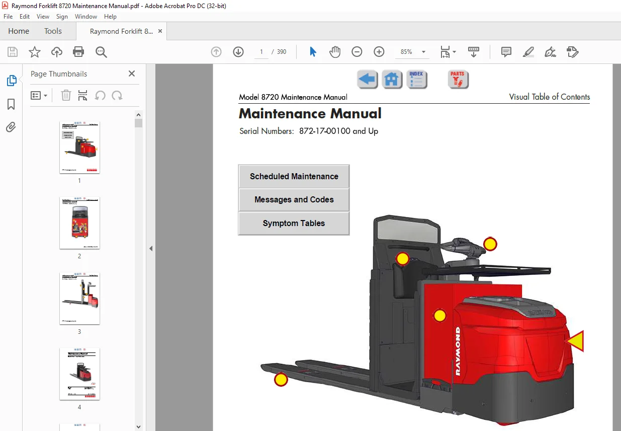
Manual Design :
- This manual is designed to give personnel, with an expected level of expertise, the technical information necessary to maintain, troubleshoot, and repair a Raymond product.
- The two-line header at the top of each page contains the name of the manual, the title of the current section, and the topic of the page.
This manual includes the following sections:
IMAGES PREVIEW OF THE MANUAL:
TABLE OF CONTENTS:
Raymond Forklift 8720 2nd Level Orderpicker Maintenance Manual SN 872-17-00101 and up – PDF DOWNLOAD
Document Revision History xi
How To Use This Manual 1-1
Manual Design 1-2
Interactive Electronic Technical Manuals 1-3
Abbreviations & Symbols 1-4
Safety 2-1
Definitions 2-2
General Safety 2-3
Battery Safety 2-6
Jacking Safety 2-9
Tractor Section 2-9
Fork Section 2-9
Operator Platform 2-9
Tie-Down for Transport 2-10
Towing 2-11
Without Brake Release Bolts 2-11
With Brake Release Bolts 2-11
Static Precautions 2-12
Welding Safety 2-13
Systems Overview 3-1
Introduction 3-2
Truck Model Identification 3-3
Truck Specifications 3-4
Special Tools 3-6
Service Key 3-6
Operator Display and Programming 3-7
Special Truck Mode 3-7
Hour Meter (H) 3-8
Error Codes (E) 3-8
Changing Truck Parameters (P) 3-8
Service Input/Output Displays 3-20
Digital Inputs/Outputs from Traction Amplifier and VM 3-20
Digital Inputs and Outputs from TIM 3-23
Digital Inputs and Outputs from PIM 3-25
FlashWare 3-27
Overview 3-27
Requirements 3-27
Installing FlashWare on PC 3-27
Connecting PC to Truck 3-27
Starting FlashWare 3-28
Scheduled Maintenance 4-1
Maintenance Guidelines 4-2
Initial 90 Day/250 Deadman Hours (HD) Maintenance 4-3
Every 180 Days or 500 Deadman Hours 4-4
Every 360 Days or 2000 Deadman Hours (HD) 4-7
Contactor Tip Inspection 4-8
Table of Contents Model 8720 Maintenance Manual
ii Publication: 1236462, Issued: 18 Jan 2018
Chain Maintenance 4-9
Lift Chain Inspection 4-9
Condition-Cause Chart 4-9
Grease Fittings 4-10
Grease Fittings (Trucks with Steel Bushings Only) 4-11
Undercarriage Pin and Bushing Inspection Points 4-12
Troubleshooting 5-1
Electrical Troubleshooting Guidelines 5-2
General 5-2
Troubleshooting the CAN Bus 5-3
Shorts to Frame 5-5
Fuses 5-7
Test/Inspection 5-7
DC Electric Motors 5-8
DC Motor Types 5-8
Inspection 5-8
Service 5-8
Open Circuit Motor Test 5-11
Grounded Motor Test 5-11
Short-Circuited Armature 5-11
Short-Circuited Winding 5-12
AC Electric Motors 5-13
AC Motor Type 5-13
Open Winding 5-13
Shorted Winding 5-13
Hydraulic Troubleshooting Guidelines 5-14
Symptom Tables: Lift/Lower System 5-15
No Lift Forks and Platform, Lift Motor Does Not Run 5-15
No or Slow Lift Forks and Platform, Lift Motor Does Run 5-16
No Lift Forks Only, Platform Lifts OK, Lift Motor Does Run 5-16
Slow Lift Forks Only, Platform Lift OK, Lift Motor Does Run 5-17
No Lift Platform Only, Forks Lift OK, Lift Motor Does Run 5-17
Slow Lift Platform Only, Forks Lift OK, Lift Motor Does Run 5-18
No or Slow Lower Forks and Platform, Lift Motor Does Run 5-18
No or Slow Lower Forks Only, Platform Lower OK,
Lift Motor Does Run 5-19
No or Slow Lower Platform Only, Forks Lower OK,
Lift Motor Does Run 5-19
Forks Drifting or Settling, Platform OK 5-20
Platform Drifting or Settling, Forks OK 5-20
Symptom Tables: Travel (Forward/Reverse) System 5-21
No Travel, Lift/Lower OK Main Contactor Does Not Close
TPA Amber LED is Flashing Once Every 2 Seconds 5-21
No Travel, No Lift/Lower TPA Flash Code 3,1 Operator
Display May Indicate Error Code E106 5-21
No Travel, Lift/Lower OK Main Contactor Does Close
TPA Amber LED is Flashing Once Every 2 Seconds 5-22
No Travel, No Lift/Lower TPA Flash Code 1,3 Operator
Display Indicates Error Code E202 5-22
No Travel, No Lift/Lower TPA Flash Code 1,2 Operator
Display Indicates Error Code E201 5-22
Model 8720 Maintenance Manual Table of Contents
Publication: 1236462, Issued: 18 Jan 2018 iii
No Travel, Main Contactor Does Not Close TPA Flash Code 3,9
Operator Display Indicates Error Code E107 5-23
Slow Travel, Lift/Lower OK No Fault Codes 5-23
No Maximum Tractor-First Speed, Travel/Lift/Lower OK
No Fault Codes 5-23
No Truck Functions Active TPA Flash Code 1,8, (Excessive
Battery Voltage) Operator Display May Indicate E222 5-23
No Truck Functions Active TPA Flash Code 1,7, (Low Battery
Voltage) Operator Display May Indicate E221 5-24
No Travel or Slow Travel TPA Flash Code 2,2, (Thermal Cutback)
Heatsink Temperature Exceeded 185°F (85°C)
Operator Display May Indicate Hot2 (C45) 5-24
No Travel Static Return to OFF (SRO) Fault Display May
Indicate ‘Sro’ and Error and Parameter Control Indicators
Blinking 5-24
No Travel High Pedal Disable Fault Display May Indicate
‘HPd’ and Error and Parameter Control Indicators
Blinking 5-25
Truck Does Not Accelerate Correctly 5-25
Symptom Tables: Steering System 5-26
Steering Drifts Either Left or Right Requiring
Constant Correction 5-26
HPd Fault is on the Display After Power ON and
Requesting Travel 5-26
Troubleshooting the PICK2PALLET™ LED Light System 5-27
None of the Lights Blink During Operation 5-27
Messages and Codes 6-1
List of Messages and Codes 6-2
Traction Power Amplifier LED Diagnostics 6-5
Traction Power Amplifier Flash Codes 6-6
Tractor Interface Module Flash Codes 6-8
Platform Interface Module Flash Codes 6-9
Caution and Error Codes 6-10
Message and Caution Codes 6-11
Code ‘GATE’ 6-11
Code ‘SLO’ 6-11
Code ‘Sro’ (C14) 6-11
Code ‘LoGn’ (C15) (iWAREHOUSE® Only) 6-12
Code C19 6-12
Code ‘HPd’ (C20) 6-12
Code C21 6-13
Code C22 6-13
Code C26 6-13
Code C27 6-14
Code C33 6-14
Code C35 6-14
Code C36 6-15
Code C37 6-15
Code C38 6-15
Code CENT (C39) (Models with Orderpicking Option) 6-16
Code Lo (C41) 6-16
Code Hi (C42) 6-16
Table of Contents Model 8720 Maintenance Manual
iv Publication: 1236462, Issued: 18 Jan 2018
Code Cold (C43) 6-17
Code Hot1 (C44) 6-17
Code Hot2 (C45) 6-18
Code C46 (iWAREHOUSE® Only) 6-18
Code C47 (iWAREHOUSE® Only) 6-18
Code C50 6-19
Code C51 6-19
Code C52 6-19
Code C57 6-20
Code C60 6-20
Code C61 6-20
Code C62 6-21
Code C65 6-21
Code C66 6-21
Code C67 6-22
Code C68 6-22
Code C70 6-22
Code C71 6-23
Code C72 6-23
Code C74 6-23
Code C75 6-24
Code C76 6-24
Code C77 6-24
Code C78 6-25
Code C79 6-25
Code C80 6-25
Code C81 6-26
Code C82 6-26
Code C83 6-27
Code C84 6-27
Code C85 6-27
Code C86 6-28
Code C87 6-28
Code C88 6-28
Code C89 6-29
Code C90 6-29
Code C94 6-30
Code C326 6-30
Code C327 6-31
Code C328 6-31
Code C329 6-31
Code C330 6-32
Code C331 6-32
Code PL_E (C361) 6-32
Code C380 6-33
Code C383 6-33
Code C384 6-33
Code C387 6-34
Code C430 6-34
Code C431 6-34
Code C432 6-35
Code C433 6-35
Model 8720 Maintenance Manual Table of Contents
Publication: 1236462, Issued: 18 Jan 2018 v
Code C434 6-35
Code C435 6-36
Code C436 6-36
Code C437 6-36
Code C438 6-37
Code C439 6-37
Code C440 6-37
Code C441 6-37
Code C442 6-38
Code C443 6-38
Code C444 6-38
Code C650 6-39
Code C651 6-39
Error Codes 6-40
Code E101 6-40
Code E106 6-40
Code E107 6-41
Code E108 6-41
Code E109 6-41
Code E110 6-42
Code E140 6-42
Code E141 6-42
Code E142 6-43
Code E150 6-43
Code E157 6-43
Code E159 6-44
Code E201 6-44
Code E202 6-44
Code E203 6-45
Code E220 6-45
Code E221 6-45
Code E222 6-46
Code E223 6-46
Code E224 6-46
Code E225 6-47
Code E228 6-47
Code E230 6-47
Code E232 6-48
Code E233 6-48
Code E235 6-48
Code E236 6-49
Code E247 6-49
Code E252 6-49
Code E253 6-50
Code E690 6-50
Code E691 6-50
Code E692 6-51
Code E694 6-51
Code E695 6-51
Code E696 6-52
Code E697 6-52
Code E698 6-52
Table of Contents Model 8720 Maintenance Manual
vi Publication: 1236462, Issued: 18 Jan 2018
Code E702 6-53
Code E706 6-53
Code E708 6-53
Code E712 6-54
Code E713 6-54
Code E714 6-54
Code E715 6-55
Code E716 6-55
Code E717 6-55
Code E718 6-56
Code E719 6-56
Code E720 6-56
Code E721 6-57
Code E723 6-57
Code EPO (E920) 6-57
Component Procedures 7-1
List of Component Procedures by Truck System 7-2
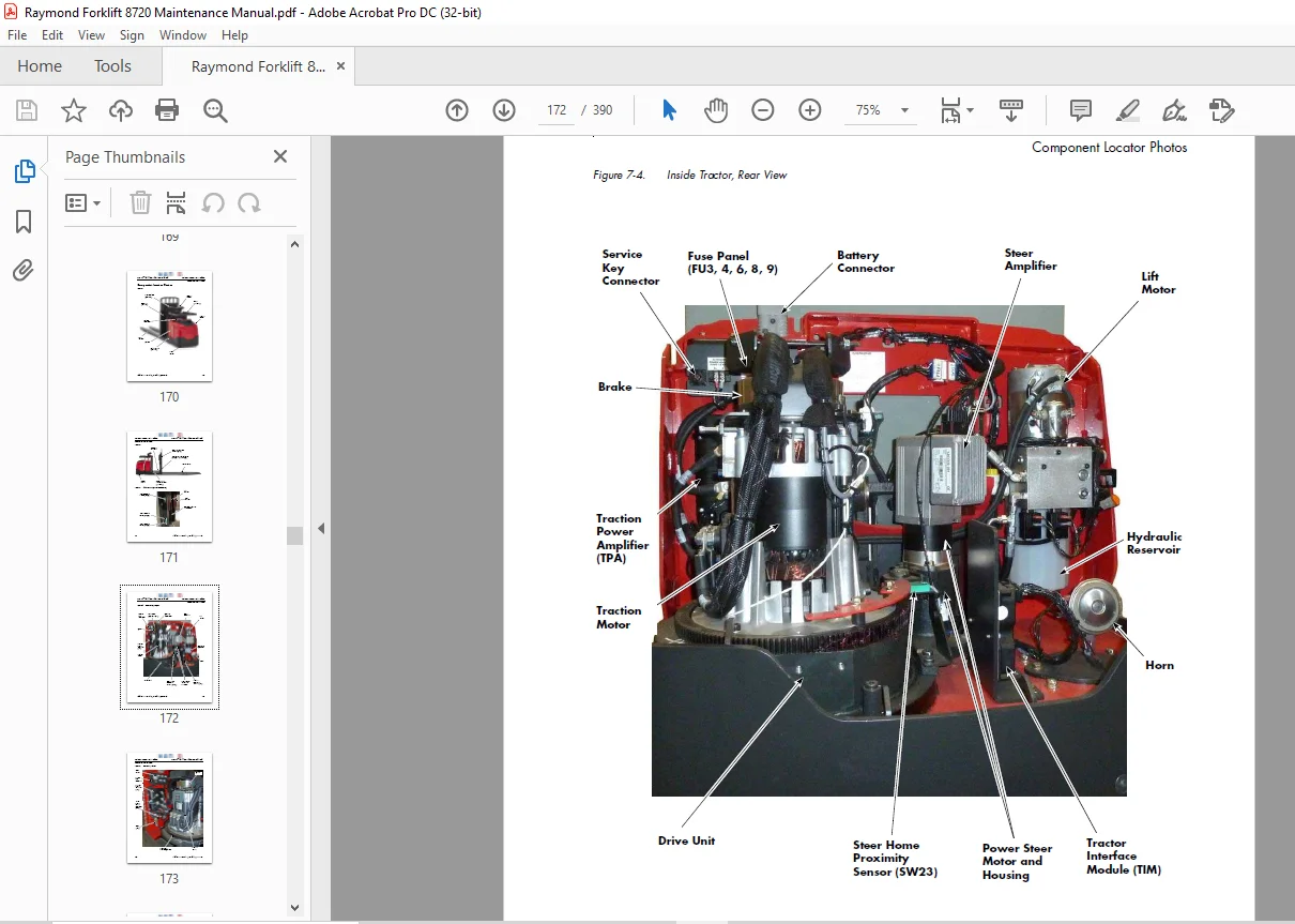
Component Locator Photos 7-5
Steering and Controls 7-13
Power Steering 7-14
Replacing the Pinion Gear 7-14
Replacing the Entire Power Steer Unit 7-15
Steer Amplifier Replacement 7-16
Checking the Steer Position 7-17
Steer Home Proximity Sensor (SW23) 7-18
Sensor Replacement 7-18
Sensor Flag Adjustment 7-18
Handle Arm and Post Assembly 7-19
Installing Handle Arm and Post 7-20
Handle Height Adjustment 7-21
Control Handle and Arm Assembly 7-22
Components 7-22
Control Handle and Arm Removal 7-26
Control Handle and Arm Installation 7-26
Upper Handle Assembly Removal 7-27
Upper Handle Assembly Installation 7-27
Upper Handle Assembly Disassembly 7-28
Horn Button/Switch Replacement 7-28
Fork Lift/Lower Button Replacement 7-29
Operator Platform Lift/Lower Button Replacement 7-29
Changing the Jog Switch 7-30
Steering Potentiometer Replacement 7-31
Keypad 7-37
Vehicle Manager 7-41
Brake Proximity Sensor 7-43
Drive and Brake 7-45
Drive Unit 7-46
Removing the Drive Unit 7-46
Removing the Steering Bearing 7-48
Installing the Steering Bearing 7-48
Disassembling the Drive Unit 7-49
Assembling the Drive Unit 7-50
Model 8720 Maintenance Manual Table of Contents
Publication: 1236462, Issued: 18 Jan 2018 vii
Checking the Gears 7-52
Adjusting the Tooth Pattern 7-52
Installing the Drive Unit 7-53
Drive Housing Lubrication 7-55
Drive Wheel 7-56
Removing the Drive Wheel 7-56
Cushion Tire Replacement 7-56
Caster Assembly 7-58
Caster Removal 7-58
Caster Height Adjustment 7-58
Caster Wheel Replacement 7-59
Caster Installation 7-60
Brake 7-61
Brake Removal 7-61
Brake Installation 7-62
Checking the Gap 7-63
Replacing the Friction Disc 7-63
Electrical Components 7-65
Battery 7-66
Trucks With Battery Gates and Rollers (Optional) 7-66
Trucks Without Battery Gates and Rollers 7-66
Battery Exterior Cleaning 7-67
Testing, Charging, and Maintenance 7-68
Maintenance-Free Batteries 7-68
Battery Storage 7-68
Battery Gate Inspection 7-68
Battery Roller Inspection 7-68
Battery Connector/Cables 7-69
Power Cables 7-71
Power Cable Repair 7-71
Wiring Harness 7-73
Wiring Harness Terminology 7-73
Wiring Harness Inspection 7-73
Wiring Harness Repair 7-73
AMP Connectors 7-75
AMP Connector Pin Extraction 7-75
AMP Connector Pin Insertion 7-76
AMP Connector Seals 7-76
AMP Harness Connector (TPA, TIM, PIM) 7-78
AMP Harness Connector Components 7-78
AMP Harness Connector Disassembly (Contact Removal) 7-78
AMP Harness Connector Assembly 7-79
Testing AMP Harness Connectors 7-80
Proximity Sensors 7-81
Fork Height Limit Switch Adjustment 7-81
Mast Proximity Sensors 7-82
Rear Control Switch Module (Optional) 7-84
Rear Control Switch Module Removal 7-84
Rear Control Switch Module Installation 7-85
Hands Free Lowering Pedal Sensor 7-86
Adjustment 7-86
Replacement 7-86
Table of Contents Model 8720 Maintenance Manual
viii Publication: 1236462, Issued: 18 Jan 2018
Hydraulic Valves 7-88
Hydraulic Solenoid 7-89
Traction Power Amplifier 7-90
Traction Power Amplifier Removal 7-90
Traction Power Amplifier Installation 7-91
Traction Amplifier Programming 7-91
Tractor Interface Module 7-92
Tractor Interface Module Removal 7-92
Tractor Interface Module Installation 7-92
Platform Interface Module 7-93
Platform Interface Module Replacement 7-93
Motors, General 7-94
Motor Brush Spring Tension 7-94
Polishing the Commutator 7-95
Traction Motor 7-96
Removing the Traction Motor 7-96
Installing the Traction Motor 7-97
Temperature Sensor Replacement 7-98
Terminal Board Removal and Replacement 7-99
Speed Sensor Replacement 7-100
Motor Disassembly 7-100
Motor Assembly 7-102
Lift Motor 7-106
General Data 7-106
Removing the Lift Motor 7-106
Installing the Lift Motor 7-106
Hydraulic Components 7-109
Hydraulic Components 7-110
General Guidelines 7-110
Hydraulic Fluid 7-111
Checking Hydraulic Fluid Level 7-111
Hydraulic Unit 7-112
Hydraulic Unit Removal 7-112
Hydraulic Unit Installation 7-112
Hydraulic Reservoir 7-113
Hydraulic Reservoir Removal 7-113
Hydraulic Reservoir Installation 7-113
Filter Screen and Suction Tube 7-114
Filter Screen and Suction Tube Removal 7-114
Filter Screen and Suction Tube Installation 7-114
Hydraulic Pump 7-115
Pump Removal 7-115
Pump Installation 7-115
Adjusting Hydraulic Pump Relief Valve Pressure 7-116
Checking Relief Valve Setting 7-116
Hydraulic Ram 7-118
Inspecting Hydraulic Ram 7-118
Removing Hydraulic Ram 7-118
Installing Hydraulic Ram 7-121
Hydraulic Cylinder Seals 7-123
Disassembling the Cylinder 7-123
Assembling the Cylinder 7-124
Model 8720 Maintenance Manual Table of Contents
Publication: 1236462, Issued: 18 Jan 2018 ix
Operator Platform Lift Cylinder Replacement 7-125
Mast 7-127
Top Linkage Subassembly 7-128
Removing the Top Linkage Subassembly 7-128
Installing the Top Linkage Subassembly 7-129
Pull Rod Subassembly 7-131
Removing the Pull Rod Subassembly 7-131
Installing the Pull Rod Subassembly 7-132
Load Wheels 7-134
Dual Axle Tandem Load Wheels 7-135
Pallet Entry Sliders 7-136
Slider Replacement 7-136
Pallet Entry Rollers (Optional) 7-137
Roller Replacement 7-137
Fork Height Adjustment 7-138
Measurement/Adjustment 7-139
Downstop Adjustment 7-139
Pallet Entry/Exit Enhancements 7-141
Operator Platform 7-143
Operator Platform Removal 7-143
Operator Platform Installation 7-144
Inner Telescopic 7-146
Inner Telescopic Removal 7-146
Inner Telescopic Installation 7-147
Lift Chain 7-148
Replacement 7-148
Lift Chain Maintenance 7-149
Chain Anchor Replacement 7-149
Lift Chain Pulley Sheave Replacement 7-151
Mast Bearings and Shims 7-152
Replacement 7-152
Options 7-153
Cold Storage Conditioning 7-154
Battery Spacer Kit Installation 7-155
Part Selection 7-156
Installation 7-157
Accessory Bar Kit Installation 7-158
Accessory Bar Installation 7-159
Battery Gate Interlock Sensors 7-161
Battery Gate Interlock Sensor Replacement 7-161
Battery Gate Interlock Sensor Adjustment 7-162
LED Work Light Installation 7-163
Operator Fan Installation 7-164
Theory of Operation 8-1
Definitions 8-2
Acceleration Rate 8-2
Brake Switch 8-2
Continuity 8-2
Controller Area Network (CAN) 8-2
Current Limiting 8-2
Fault Codes 8-2
High Pedal Disable (HPD) 8-2
Table of Contents Model 8720 Maintenance Manual
x Publication: 1236462, Issued: 18 Jan 2018
Neutral Braking Deceleration (Plugging) 8-2
Open Circuit 8-3
Overvoltage Cutoff 8-3
PIN-Key Code 8-3
Pulse Width Modulation 8-3
Ramp Shape 8-3
Regenerative Braking 8-3
Sequencing Delay 8-3
Short Circuit or “Short” 8-3
Speed Limiting 8-4
Static Return To Off (SRO) 8-4
Thermal Cutback (Traction Power Amplifier) 8-4
Throttle Map 8-4
Truck Off Delay (Keypad only) 8-5
Undervoltage Cutoff 8-5
VM (Vehicle Manager) 8-5
Walking Speed With Jog Button Controls 8-5
Traction System 8-6
Vehicle Manager (VM) 8-6
Traction Power Amplifier (TPA) 8-6
Battery Plugged In 8-6
Key Switch ON and MPC Energized 8-6
Travel Request, Tractor-First 8-7
Travel Request, Forks-First 8-7
Jog Button Controls Mode 8-7
Lift/Lower System 8-8
Lift 8-8
Lower 8-9
Electric Power Steering 8-10
Power Steering Potentiometers 8-10
Floor Mat Switch (SW25) 8-10
Travel Speed Reduction 8-10
PSU: Power Steering Unit 8-10
Steering 8-11
PICK2PALLET™ LED Light System 8-12
Pinout Matrix 8-13
Appendix A-1
Lubrication Equivalency Chart A-2
Thread Adhesives, Sealants, and Lubricants A-3
Component Specific Service/Torque Chart A-4
Torque Chart – Standard (Ferrous) A-7
Torque Chart – Standard (Brass) A-8
Torque Chart – Metric (Ferrous) A-9
Torque Chart – Metric (Brass) A-10
Torque Chart – Thread Forming Screws A-11
Torque Chart – Hydraulic Fittings A-13
Torque Chart – Straight Thread Face Seal O-Rings A-14
Decimal Equivalent Chart A-15
Standard/Metric Conversions A-17
Index I-1
Questions? Email us: [email protected]
PLEASE NOTE:
- This is the SAME exact manual used by your dealers to fix your vehicle.
- The same can be yours in the next 2-3 mins as you will be directed to the download page immediately after paying for the manual.
- Any queries / doubts regarding your purchase, please feel free to contact [email protected]
S.V