Raymond Forklift Courier® Lift Trucks 3010 Center Rider Pallet Trucks and Model 3020 Tow Tractors Maintenance Manual 1134255B – PDF DOWNLOAD
$29.95
Raymond Forklift Courier® Lift Trucks 3010 Center Rider Pallet Trucks and Model 3020 Tow Tractors Maintenance Manual 1134255B – PDF DOWNLOAD
Serial Numbers:
301-14-00001 and up
302-14-00001 and up
Description
Raymond Forklift Courier® Lift Trucks 3010 Center Rider Pallet Trucks and Model 3020 Tow Tractors Maintenance Manual 1134255B – PDF DOWNLOAD
FILE DETAILS:
Raymond Forklift Courier® Lift Trucks 3010 Center Rider Pallet Trucks and Model 3020 Tow Tractors Maintenance Manual 1134255B – PDF DOWNLOAD
Language : English
Pages : 392
Downloadable : Yes
File Type : PDF
Size:13 0 MB
DESCRIPTION:
Raymond Forklift Courier® Lift Trucks 3010 Center Rider Pallet Trucks and Model 3020 Tow Tractors Maintenance Manual 1134255B – PDF DOWNLOAD
Manual Design
- This manual is designed to give personnel, with an expected level of expertise, the technical information necessary to maintain, troubleshoot, and repair a Raymond product.
- The two-line running page header at the top of each page contains the name of the manual, the title of the current section, and the topic of the current page
This manual includes the following sections:
TABLE OF CONTENTS:
Raymond Forklift Courier® Lift Trucks 3010 Center Rider Pallet Trucks and Model 3020 Tow Tractors Maintenance Manual 1134255B – PDF DOWNLOAD
Page Revision Record xiii
Document Revision History xiii
Service Information Documents List xiv
How To Use This Manual 1-1
Manual Design 1-2
Interactive Electronic Technical Manuals 1-3
Abbreviations & Symbols 1-4
Abbreviations and Symbols – Guidance System. 1-6
Safety 2-1
Definitions 2-2
General Safety 2-3
Battery Safety 2-5
Jacking Safety 2-8
Tractor Section 2-8
Fork Section 2-8
Tie-Down for Transport 2-9
Towing 2-10
Without Brake Release Bolts 2-10
With Brake Release Bolts 2-10
Static Safety 2-11
Welding Safety 2-12
Systems Overview 3-1
Introduction 3-2
Truck Model Identification 3-3
Lift Truck Specifications 3-4
Special Tools 3-5
Service Key 3-6
Jumper Harness 3-6
Operator Display and Programming 3-7
Special Truck Mode 3-7
Hour Meter (H) 3-7
Error Codes (E) 3-7
Changing Truck Parameters (P) 3-8
Service Input/Output Displays 3-19
Digital Inputs/Outputs from Traction Amplifier and VM 3-19
Automated Truck 3-22
Overview 3-22
Components 3-22
Vision Guidance Unit Indicator Lights. 3-24
Graphical Operator Interface (GOI) 3-25
Guidance System Overview 3-26
Operating the Automated Lift Truck 3-26
Using the GOI 3-26
Startup 3-26
Opening Screen in Manual Mode. 3-26
Main Menu Screen 3-27
“Training and Service” Menu 3-28
Table of Contents Raymond® Model 3010/3020 Maintenance Manual
ii Publication: 1134255, Revised: 15 Sep 2017
Operating Procedures 3-42
Backing Up and Restoring Routes. 3-43
Changing Log Level. 3-44
FlashWare 3-46
Overview 3-46
Requirements 3-46
Installing FlashWare on PC. 3-46
Connecting PC to Truck 3-46
Starting FlashWare. 3-46
Scheduled Maintenance 4-1
Maintenance Guidelines 4-2
Initial 90 Day/250 Deadman Hours (HD) Maintenance 4-3
Every 180 Days or 500 Deadman Hours 4-4
Every 360 Days or 2000 Deadman Hours (HD) 4-7
Contactor Tip Inspection 4-8
Grease Fittings (All Models) 4-9
Grease Fittings (Trucks without Steel Bushings Only) 4-10
Undercarriage Pin and Bushing Inspection Points 4-11
Troubleshooting 5-1
How to Use This Section 5-2
Electrical Troubleshooting Guidelines 5-3
General 5-3
Troubleshooting the CAN Bus. 5-3
Shorts to Frame 5-6
Fuses 5-9
Test/Inspection 5-9
DC Electric Motors 5-10
DC Motor Types 5-10
Inspection 5-10
Service 5-10
Open Circuit Motor Test 5-12
Grounded Motor Test 5-13
Short-Circuited Armature 5-13
Short-Circuited Winding 5-13
AC Electric Motors 5-14
AC Motor Type 5-14
Open Winding 5-14
Shorted Winding. 5-14
Hydraulic Troubleshooting Guidelines 5-15
Symptom Tables: Lift/Lower System 5-16
No Lift, Lift Motor Does Not Run, Travel is OK 5-16
No Lift or Slow Lift, Lift Motor Does Run 5-17
No Lower, Lift and Travel OK 5-17
Unable to Pick Up a Load 5-18
Slow Lower 5-18
Load Drifting/Settling. 5-19
Symptom Tables: Travel (Forward/Reverse) System 5-20
No Travel, Lift/Lower OK. Main Contactor Does Not Close.
TA Amber LED is Flashing Once Every 2 Seconds 5-20
No Travel, No Lift/Lower. TA Flash Code 3,1.
Operator Display May Indicate Error Code E106 5-20
Raymond® Model 3010/3020 Maintenance Manual Table of Contents
Publication: 1134255, Revised: 15 Sep 2017 iii
No Travel, No Lift/Lower. TA Flash Code 1,3.
Operator Display Indicates Error Code E202 5-21
No Travel, No Lift/Lower. TA Flash Code 1,2.
Operator Display Indicates Error Code E201 5-21
No Travel, Main Contactor Does Not Close. TA Flash Code 3,9.
Operator Display Indicates Error Code E107 5-21
Slow Travel, Lift/Lower OK. No Fault Codes 5-22
No Emergency Reverse, Travel/Lift/Lower OK.
No TA Flash Codes 5-22
No Rabbit Speed, Travel/Lift/Lower OK. No Fault Codes 5-22
No Truck Functions Active. TA Flash Code 1,8, (Excessive
Battery Voltage). Operator Display May Indicate E222 5-22
No Truck Functions Active. TA Flash Code 1,7, (Low
Battery Voltage). Operator Display May Indicate E221 5-23
No Travel or Slow Travel. TA Flash Code 2,2,
(Thermal Cutback) Heatsink Temperature Exceeded
185°F (85°C). Operator Display May Indicate Hot2 (C45). 5-23
No Travel. Static Return to OFF (SRO) Fault.
Display may indicate ‘Sro’ and Error and Parameter
Control Indicators Blinking 5-23
No Travel. High Pedal Disable Fault.
Display may indicate ‘HPd’ and Error and Parameter
Control Indicators Blinking 5-24
Truck Does Not Accelerate Correctly 5-24
Symptom Tables: Wiring System 5-25
Symptom Tables: Guidance System 5-26
Jumper Harness Installation. 5-26
Unit Deviates from Trained Path 5-27
Erratic Behavior 5-27
Unit Accelerates Unexpectedly 5-27
Frequent Stoppages During Path Follow 5-28
Unexpected Behavior at Intersections 5-29
Frequent Localization Failures 5-29
Light Curtain Module Intermittently Showing Obstruction 5-30
Low Battery Warning 5-30
Intermittent Communication Codes 5-30
Automated Truck Will Not Move 5-31
Obstruction Sensor Displays an Error Code (E1, and so forth) 5-31
No GOI display 5-32
Automated Truck Boots with Camera Error. 5-32
Steering Does Not Complete Alignment 5-32
VIM Lights Not On 5-33
GOI Screen Hangs Up During Start UP 5-33
Green “GO” Button Does Not Illuminate 5-33
VGU Indicator Lights Do Not Illuminate 5-33
GOI Displays “No Media Device Detected” 5-34
GOI Displays “Not Enough Space on USB Disk” 5-34
GOI Does Not Acknowledge Key Presses 5-34
SICK “Windshield” LED Illuminated on Obstruction
Sensor or Light Curtain Module 5-34
Pallet Does Not Disengage 5-35
Table of Contents Raymond® Model 3010/3020 Maintenance Manual
iv Publication: 1134255, Revised: 15 Sep 2017
Messages and Codes 6-1
List of Messages and Codes 6-2
Traction Amplifier LED Diagnostics 6-6
Traction Amplifier Flash Codes 6-7
Caution and Error Codes 6-9
Message and Caution Codes 6-10
Code ‘tESt’ 6-10
Code ‘GaTE’ 6-10
Code ‘SLO’ 6-10
Code ‘Sro’ (C14) 6-11
Code ‘LoGn’ (C15) (iWAREHOUSE Only) 6-11
Code C19 6-11
Code ‘HPd’ (C20) 6-12
Code C21 6-12
Code C22 6-13
Code C24 6-13
Code C25 6-13
Code C26 6-14
Code C27 6-14
Code C30 6-14
Code C31 6-15
Code C32 6-15
Code C33 6-15
Code C34 6-16
Code C35 6-16
Code C36 6-16
Code HPd (C38) 6-17
Code CENT C39 (Models 3010 with Orderpicking Option) 6-17
Code C40 6-17
Code Lo (C41) 6-18
Code Hi (C42) 6-18
Code Cold (C43) 6-18
Code Hot1 (C44) 6-19
Code Hot2 (C45) 6-19
Code C46 (iWAREHOUSE Only) 6-20
Code C47 (iWAREHOUSE Only) 6-20
Code C50 6-20
Code C51 6-21
Code C52 6-21
Code C57 6-21
Code C60 6-22
Code C61 6-22
Code C62 6-22
Code C63 6-23
Code C64 6-23
Code C65 6-23
Code C66 6-24
Code C67 6-24
Code C68 6-25
Code C70 6-25
Code C71 6-26
Code C72 6-26
Raymond® Model 3010/3020 Maintenance Manual Table of Contents
Publication: 1134255, Revised: 15 Sep 2017 v
Code C74 6-27
Code C75 6-27
Code C76 6-27
Code C77 6-28
Code C78 6-28
Code C79 6-28
Code C80 6-29
Code C81 6-29
Code C82 6-30
Code C83 6-30
Code C84 6-30
Code C85 6-31
Code C86 6-31
Code C87 6-31
Code C88 6-32
Code C89 6-32
Code C90 6-32
Code C91 6-33
Code C92 6-33
Code C93 6-33
Code C94 6-34
Error Codes 6-35
Code E101 6-35
Code E106 6-35
Code E107 6-36
Code E108 6-36
Code E109 6-36
Code E110 6-37
Code E140 6-37
Code E141 6-37
Code E142 6-38
Code E150 6-38
Code E157 6-38
Code E159 6-39
Code E160 6-39
Code E201 6-40
Code E202 6-40
Code E203 6-40
Code E220 6-41
Code E221 6-41
Code E222 6-41
Code E223 6-42
Code E224 6-42
Code E225 6-42
Code E228 6-43
Code E230 6-43
Code E232 6-43
Code E233 6-44
Code E235 6-44
Code E236 6-44
Code E247 6-45
Code E252 6-45
Table of Contents Raymond® Model 3010/3020 Maintenance Manual
vi Publication: 1134255, Revised: 15 Sep 2017
Code E253 6-45
GOI Message Reference 6-46
Code 15 or 44. 6-67
Component Procedures 7-1
List of Component Procedures by Truck System 7-2
Component Locator Photos 7-5
Steering and Controls. 7-9
Electric Power Steering 7-10
Replacing the Pinion Gear 7-10
Replacing the Entire Power Steer Unit 7-11
PSU Controller Replacement 7-11
Steer Home Proximity Sensor (SW23) 7-13
Sensor Replacement 7-13
Sensor Flag Adjustment 7-13
Power Steer Handle and Post Assembly 7-14
Removing Handle and Post 7-14
Installing Handle and Post 7-14
Handle Height Adjustment 7-14
Control Head Removal 7-15
Control Head Installation 7-15
Steering Potentiometer Replacement 7-16
Control Handle 7-21
Control Handle Disassembly. 7-22
Drive and Brake 7-25
Drive Unit 7-26
Removing the Drive Unit 7-26
Removing the Steering Bearing 7-28
Installing the Steering Bearing 7-28
Disassembling the Drive Unit 7-29
Assembling the Drive Unit 7-30
Checking the Gears 7-32
Adjusting the Tooth Pattern 7-32
Installing the Drive Unit 7-33
Drive Housing Lubrication 7-35
Drive Wheel 7-36
Removing the Drive Wheel 7-36
Cushion Tire Replacement 7-36
Shim Caster Adjustment 7-38
Casters (Spring-Loaded) 7-39
Spring-Loaded Caster Removal 7-39
Wheel Removal 7-39
Caster Disassembly 7-40
Caster Assembly. 7-41
Wheel Installation. 7-41
Spring-Loaded Caster Installation. 7-42
Brake 7-43
Brake Removal 7-43
Brake Installation. 7-44
Checking the Gap 7-44
Replacing the Rotor 7-44
Raymond® Model 3010/3020 Maintenance Manual Table of Contents
Publication: 1134255, Revised: 15 Sep 2017 vii
Electrical Components 7-45
Battery 7-46
Trucks With Battery Gates and Rollers (Optional) 7-46
Battery Removal 7-46
Battery Installation 7-46
Battery Gates (Optional) 7-46
Battery Gate Inspection 7-46
Battery Rollers (Optional) 7-46
Battery Roller Inspection. 7-46
Battery Roller Replacement 7-46
Trucks Without Battery Gates and Rollers 7-46
Battery Removal 7-46
Battery Installation 7-46
Battery Exterior Cleaning 7-47
Testing, Charging, and Maintenance 7-48
Maintenance-Free Batteries 7-48
Battery Storage 7-48
Power Cables 7-49
Power Cable Repair 7-49
Wiring Harness 7-51
Wiring Harness Terminology 7-51
Inspecting a Wiring Harness 7-51
Repairing a Wiring Harness. 7-51
AMP Water-Resistant Connectors 7-53
AMP Connector Pin Extraction 7-53
AMP Connector Pin Insertion 7-54
AMP Connector Seals 7-54
AMP Harness/Traction Amplifier Connector 7-56
AMP Harness Connector Components 7-56
AMP Harness Connector Disassembly (Contact Removal) 7-56
AMP Harness Connector Assembly 7-57
Testing AMP Harness Connectors 7-58
Lift-Limit Switch (SW8) 7-59
Adjusting the Limit Switch 7-59
Lower Limit Switch 7-60
Hydraulic Solenoids 7-61
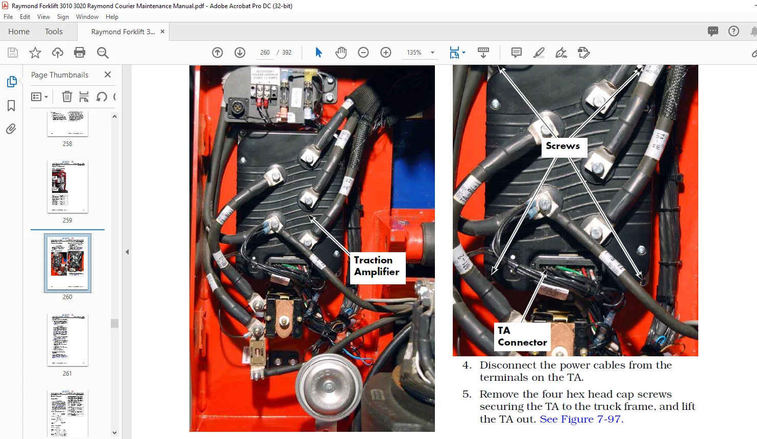
Traction Amplifier 7-62
Removing the Traction Amplifier 7-62
Installing the Traction Amplifier 7-63
Programming the Traction Amplifier 7-63
Motors, General 7-64
Terminal Nuts. 7-64
Traction Motor 7-65
Removing the Traction Motor 7-65
Installing the Traction Motor. 7-67
Temperature Sensor Replacement 7-68
Terminal Board Removal and Replacement 7-69
Speed Sensor Replacement 7-70
Motor Disassembly 7-71
Motor Assembly 7-73
Table of Contents Raymond® Model 3010/3020 Maintenance Manual
viii Publication: 1134255, Revised: 15 Sep 2017
Lift Motor 7-76
General Data 7-76
Removing the Lift Motor 7-76
Installing the Lift Motor 7-76
Guidance System Components 7-79
Automated Truck Guidance Components 7-79
Powering Down. 7-80
Powering ON. 7-80
Arch 7-81
Floor Mat 7-81
Load Sensor 7-81
Component Removal and Replacement 7-81
Cable Connector Locator Chart. 7-82
Graphical Operator Interface (GOI) 7-83
Removing the GOI 7-83
Installing the GOI 7-83
Vision Guidance Unit (VGU) 7-84
Cleaning the Camera Lenses. 7-84
Removing the VGU 7-84
Installing the VGU 7-85
Light Curtain Module (LCM) 7-87
Light Curtain Module Removal 7-87
Light Curtain Module Installation 7-87
Light Curtain Module Calibration 7-87
Light Curtain Module Lens Cleaning 7-87
Vehicle Interface Module (VIM) 7-90
Removing the VIM 7-90
Installing the VIM 7-90
Power Distribution Module (PDM) 7-91
Removing the PDM 7-91
Installing the PDM 7-91
Obstruction (SICK) Sensor (OS) 7-92
Obstruction Sensor Removal 7-92
Obstruction Sensor Installation 7-92
Cleaning the SICK Shields 7-92
Leveling the Obstruction Sensor 7-92
Steer Encoder 7-94
Steer Encoder Adjustment 7-94
Steering Calibration 7-94
Straight-Line Test 7-95
Hydraulic Components 7-97
Hydraulic Components 7-98
General Guidelines 7-98
Hydraulic Fluid 7-99
Checking Hydraulic Fluid Level 7-99
Hydraulic Unit 7-100
Removing the Hydraulic Unit 7-100
Installing the Hydraulic Unit 7-100
Hydraulic Reservoir 7-101
Removing the Hydraulic Reservoir 7-101
Installing the Hydraulic Reservoir 7-101
Raymond® Model 3010/3020 Maintenance Manual Table of Contents
Publication: 1134255, Revised: 15 Sep 2017 ix
Filter Screen and Suction Tube 7-102
Removing Filter Screen and Suction Tube 7-102
Installing Filter Screen and Suction Tube 7-102
Hydraulic Pump 7-103
Removing the Pump 7-103
Installing the Pump 7-103
Adjusting Hydraulic Pump Relief Valve Pressure 7-104
Checking Relief Valve Setting 7-104
Alternate Method Using Rated Load on Pallets 7-105
Hydraulic Ram 7-106
Inspecting Hydraulic Ram. 7-106
Removing Hydraulic Ram 7-106
Installing Hydraulic Ram 7-108
Hydraulic Cylinder Seals 7-110
Disassembling the Cylinder. 7-110
Assembling the Cylinder 7-111
Cast Hydraulic Cylinder Repair 7-112
Disassembly 7-112
Assembly 7-112
Mast 7-113
Top Linkage Subassembly 7-114
Removing the Top Linkage Subassembly 7-114
Installing the Top Linkage Subassembly 7-115
Pull Rod Subassembly 7-117
Removing the Pull Rod Subassembly. 7-117
Installing the Pull Rod Subassembly 7-118
Load Wheels 7-120
Single Load Wheels – Model 3010 7-120
Tandem Load Wheels – Model 3010. 7-121
Suspension Wheel – Model 3020 7-122
Pallet Entry Sliders 7-124
Slider Replacement 7-124
Pallet Entry Rollers 7-125
Roller Replacement 7-125
Fork Height Adjustment 7-126
Measurement/Adjustment 7-127
Downstop Installation 7-128
Downstop Adjustment. 7-128
Pallet Entry/Exit Enhancements. 7-129
Options. 7-133
Cold Storage Conditioning 7-134
Battery Spacer Kit Installation 7-135
Part Selection 7-136
Installation 7-137
Battery Gate Interlock Sensors 7-138
Battery Gate Interlock Sensor Replacement. 7-138
Battery Gate Interlock Sensor Adjustment 7-138
Table of Contents Raymond® Model 3010/3020 Maintenance Manual
x Publication: 1134255, Revised: 15 Sep 2017
Theory of Operation 8-1
Definitions 8-2
Acceleration Rate 8-2
Continuity 8-2
Controller Area Network (CAN) 8-2
Current Limiting. 8-2
Fault Codes 8-2
High Pedal Disable (HPD) 8-2
Neutral Plugging Rate (Deceleration) 8-2
Open Circuit. 8-2
Overvoltage Cutoff 8-2
PIN-Key Code 8-2
Pulse Width Modulation 8-3
Ramp Shape 8-3
Regenerative Braking 8-3
Sequencing Delay 8-3
Short Circuit or “Short” 8-3
Speed Limiting 8-3
Static Return To Off (SRO) 8-4
Thermal Cutback (Traction Amplifier) 8-4
Throttle Map. 8-4
Truck Off Delay (Keypad only). 8-4
Undervoltage Cutoff 8-4
VM (Vehicle Manager) 8-4
Walking Speed 8-4
Traction System 8-5
Vehicle Manager (VM) 8-5
Traction Amplifier (TA) 8-5
Battery Plugged In 8-5
Key Switch ON 8-6
Travel Request, Tractor-First (Manual Mode). 8-6
Travel Request, Forks-First 8-7
Travel Request, Tractor-First (Automatic Mode) 8-7
Floor Mat Switch (SW25) JP37-1 input to the TA 8-7
E-Stop Circuit 8-8
Intersection Control 8-8
Lift/Lower System 8-9
Lift (Manual Mode) 8-9
Lift (Automatic Mode) 8-9
Lower (Manual Mode) 8-9
Lower (Automatic Mode) 8-9
Theory of Operation – Electric Power Steering 8-10
Power Steering Potentiometers 8-10
PSU: Power Steering Unit 8-10
Steering (Manual Mode) 8-10
Steering (Automatic Mode) 8-11
Travel Speed Reduction (Manual Mode). 8-11
Travel Speed Reduction (Automatic Mode) 8-11
Jumper Harness. 8-11
Pinout Matrix 8-12
Raymond® Model 3010/3020 Maintenance Manual Table of Contents
Publication: 1134255, Revised: 15 Sep 2017 xi
Appendix. A-1
Lubrication Equivalency Chart A-2
Thread Adhesives, Sealants, and Lubricants A-3
Component Specific Service/Torque Chart A-4
Torque Chart – Standard (Ferrous) A-7
Torque Chart – Standard (Brass) A-8
Torque Chart – Metric (Ferrous) A-9
Torque Chart – Metric (Brass) A-10
Torque Chart – Thread Forming Screws A-11
Torque Chart – Metric Thread-Forming Screws A-13
Torque Chart – Hydraulic Fittings A-14
Torque Chart – Straight Thread Face Seal O-Rings A-15
Decimal Equivalent Chart A-16
Standard/Metric Conversions A-18
Index I-1
IMAGES PREVIEW OF THE MANUAL:
Contact us: [email protected]
https://vimeo.com/838614874?share=copy
PLEASE NOTE:
- This is the SAME MANUAL used by the dealerships to diagnose your vehicle
- No waiting for couriers / posts as this is a PDF manual and you can download it within 2 minutes time once you make the payment.
- Your payment is all safe and the delivery of the manual is INSTANT – You will be taken to the DOWNLOAD PAGE.
- So have no hesitations whatsoever and write to us about any queries you may have : heydownloadss @gmail.com
S.M