Raymond Forklift The Raymond ® Transtacker TRT Maintenance Manual SNTRT-19-00320 and up – PDF DOWNLOAD
$32.95
Raymond Forklift The Raymond ® Transtacker TRT Maintenance Manual SNTRT-19-00320 and up – PDF DOWNLOAD
Description
Raymond Forklift The Raymond ® Transtacker TRT Maintenance Manual SNTRT-19-00320 and up – PDF DOWNLOAD
FILE DETAILS:
Raymond Forklift The Raymond ® Transtacker TRT Maintenance Manual SNTRT-19-00320 and up – PDF DOWNLOAD
Language : English
Pages :604
Downloadable : Yes
File Type : PDF
Size: 36.1 MB
DESCRIPTION:
Raymond Forklift The Raymond ® Transtacker TRT Maintenance Manual SNTRT-19-00320 and up – PDF DOWNLOAD
Manual Design
This manual is designed to give personnel, with an expected level of expertise, the technical information necessary to maintain, troubleshoot, and repair a Raymond product. The two-line header at the top of each page contains the name of the manual, the title of the current section, and the topic of the page.
This manual includes the following sections:
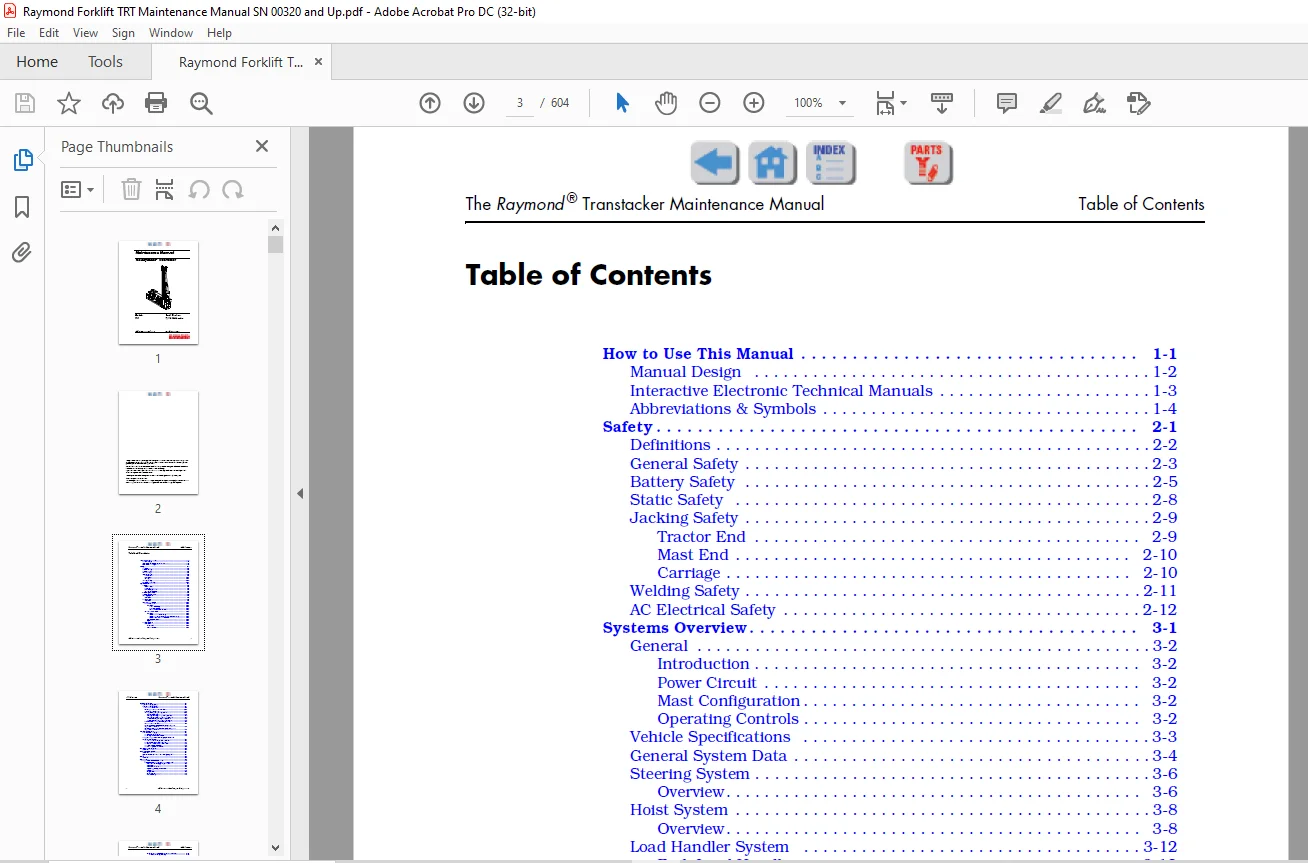
TABLE OF CONTENTS:
Raymond Forklift The Raymond ® Transtacker TRT Maintenance Manual SNTRT-19-00320 and up – PDF DOWNLOAD
How to Use This Manual 1-1
Manual Design 1-2
Interactive Electronic Technical Manuals 1-3
Abbreviations & Symbols 1-4
Safety 2-1
Definitions 2-2
General Safety 2-3
Battery Safety 2-5
Static Safety 2-8
Jacking Safety 2-9
Tractor End 2-9
Mast End 2-10
Carriage 2-10
Welding Safety 2-11
AC Electrical Safety 2-12
Systems Overview 3-1
General 3-2
Introduction 3-2
Power Circuit 3-2
Mast Configuration 3-2
Operating Controls 3-2
Vehicle Specifications 3-3
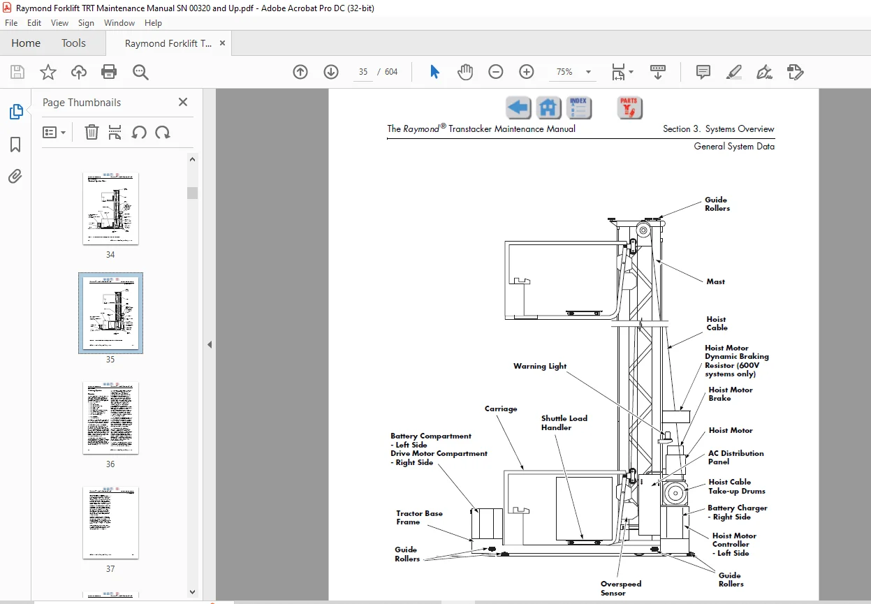
General System Data 3-4
Steering System 3-6
Overview 3-6
Hoist System 3-8
Overview 3-8
Load Handler System 3-12
Fork Load Handler 3-12
Overview 3-12
Reach Assembly 3-12
Rotate Assembly 3-13
Fork Load Handler Controls 3-13
Shuttle Load Handler 3-15
Overview 3-15
Shuttle Platform Assembly 3-15
Shuttle Motor/Brake/Gear Reducer Assembly 3-15
Shuttle Load Handler Controls 3-16
Shuttle Select Panel 3-17
Options 3-18
Traction System 3-19
Overview 3-19
Drive Unit 3-19
Control Devices 3-19
Table of Contents The Raymond ® Transtacker Maintenance Manual
ii Publication: 1314609/001, Issued: 25 Jan 2019
Operator Displays 3-21
Operator Display (OD1) 3-21
Operator Display (OD2) 3-21
General Instructions 3-22
Entering numbers and characters: 3-23
Password Instructions 3-23
Analog and Digital I/O Diagnostics 3-23
Analog Diagnostics 3-23
Carriage PLC Digital Input Diagnostics 3-24
Carriage PLC Digital Output Diagnostics 3-24
Tractor PLC Digital Input Diagnostics 3-25
Tractor PLC Digital Output Diagnostics 3-25
Load Handler and Option Configuration: 3-25
Handle Learn Procedure 3-26
Reach Feedback Potentiometer (VR6) Setup and
Adjustment Procedure 3-28
Rotate Feedback Potentiometer (VR5) Setup and
Adjustment Procedure 3-29
VFI Display Operation 3-31
How to Use the Display 3-31
To Set a Parameter Filter 3-35
To Change a Parameter Value 3-35
Using the “Programmed” VFI Display to Download
Parameters to the VFI: 3-37
To Transfer the Settings to the Inverter 3-37
Perform Motor Data Identification: 3-37
To Start the Motor Data Identification 3-38
To Finish Commissioning 3-38
To Manually Enter Parameters 3-38
DC to DC Power Supplies 3-40
Overview 3-40
Battery Charger System 3-41
Overview 3-41
Special Considerations for Cold Storage Operation 3-41
Horns 3-42
Overview 3-42
Special Tools 3-43
Programmable Maintenance Tool 3-43
Programmable Maintenance Tool – Model 1313 3-43
Main Screen and Apps Organization 3-45
Parameters 3-46
Parameter Structure 3-47
Adjusting/Editing a Parameter 3-47
Monitor 3-48
Diagnostics 3-49
Present Errors Folder 3-49
Fault History Folder 3-49
Programmable Maintenance Tool – Model 1311 3-50
Backwards Compatibility 3-51
Program Parameters 3-51
Changing a Parameter 3-52
Monitor Mode 3-53
Faults and Diagnostic History 3-53
Cloning 3-53
Scheduled Maintenance 4-1
Maintenance Guidelines 4-2
Maintenance Schedules 4-2
Daily Checklist 4-3
Every 60 Days or 250 Deadman Hours (HD) 4-5
90 Day Inspection 4-10
Every 180 Days or 1000 Deadman Hours (HD) 4-11
Every 360 Days or 2000 Deadman Hours (HD) 4-13
Scheduled Maintenance, Lubrication, and Inspection Points 4-14
Troubleshooting 5-1
How to Use This Chapter 5-2
Electrical Troubleshooting Guidelines 5-3
Shorts to Frame Test 5-4
AC Electrical 5-6
General Test Procedures 5-6
Truck Ground Test 5-6
Phase Isolation Test 5-6
Ground Verification Circuitry 5-6
Input Power Collectors and Busses 5-7
Troubleshooting Wiring Problems 5-8
Electrical Connections 5-9
Terminology 5-9
Electrical Connection Locator Chart 5-9
Steer Motor/Amplifier Connections 5-12
Fuses/Circuit Breakers 5-13
Test/Inspection 5-13
Fuse Locator Chart 5-13
Fuse Locations 5-15
Circuit Breaker Locator Chart 5-18
Gear Reducer Troubleshooting and Repair (Reach/Shuttle) 5-19
Brake Assembly Troubleshooting and Repair (Reach/Shuttle) 5-21
DC Lowering Troubleshooting 5-22
DC Lower Function Inoperative 5-22
Symptom Tables 5-23
Truck Completely Inoperative 5-23
Rotate 5-24
Erratic/Intermittent Operation 5-24
Noisy Operation 5-26
Slow Operation 5-26
One Direction Only 5-28
None 5-29
Table of Contents The Raymond ® Transtacker Maintenance Manual
iv Publication: 1314609/001, Issued: 25 Jan 2019
Reach/Retract — Fork and Shuttle Load Handlers 5-32
Erratic/Intermittent Operation 5-32
Noisy Operation 5-36
Slow Operation 5-38
No Reach 5-42
No Retract 5-44
Lift/Lower System 5-46
Intermittent Lift and Lower 5-46
Incorrect or No Decels, Lift and/or Lower 5-46
Slow Lift or Lower 5-47
None 5-47
Brake Module (BRM) 5-49
Travel Problems 5-50
None 5-50
Slow or Sluggish Acceleration 5-51
Slow or Uneven Travel Speeds 5-52
Electrical Problems 5-53
Traction (Drive) Motor Brushes Arcing 5-53
ODI Problems (OD1 and OD2) 5-53
Fuses Blowing 5-53
Messages, Codes and Tests 6-1
List of Codes 6-3
List of Tests, Checks, and Adjustments 6-4
Code 1—Hoist System Fault 6-5
VFI Fault Codes and Tests 6-6
Code 2—Traction System Fault 6-11
Code 3—Steer System Fault 6-16
Code 4—Traction Control Potentiometer (VR2) Out-of-Range 6-23
Code 4 Tests and Adjustments 6-24
Code 5—Hoist Control Potentiometer (VR3) Out-of-Range 6-25
Code 5 Tests and Adjustments 6-26
Code 6—Load Handler Control Potentiometer (VR4) Out-of-Range 6-27
Code 6 Tests and Adjustments 6-28
Code 7—Rotate Feedback Potentiometer (VR5) Out-of-Range (Fork Load Handler
Only) 6-29
Code 7 Tests and Adjustments (Fork Load Handler Only) 6-30
Code 8—Reach Feedback Potentiometer (VR6) Out-of-Range (Fork Load Handler
Only) 6-31
Code 8 Tests and Adjustments (Fork Load Handler Only) 6-32
Code 9—Hoist Enable Switch (S10) Closed on Start-up 6-33
Code 9 Tests and Adjustments 6-33
Code 10—Travel Enable Switch (S11) Closed on Start-up 6-34
Code 10 Tests and Adjustments 6-34
Code 11—Load Handler Enable Switch (S9) Closed on Start-up 6-35
Code 11 Tests and Adjustments 6-35
Code 12—Deadman Switch(es) (S2 and/or S3) Closed on Start-up 6-36
Code 12 Tests and Adjustments 6-36
Code 13—Loss of Communications Between PLCs 6-37
Code 13 Checks and Tests 6-38
IE FC Cable and Plug Assembly 6-38
Code 14— Vertical Photo-eye Error 6-41
Code 14 Tests, Checks, and Adjustments 6-42
The Raymond ® Transtacker Maintenance Manual Table of Contents
Publication: 1314609/001, Issued: 25 Jan 2019 v
Code 15—Drive Wheel Not Centered on AC Power 6-43
Code 15 Checks and Tests 6-44
Code 16—Steer Position Feedback Potentiometer (VR1)
Out-of-Range 6-45
Code 16 Checks and Tests 6-46
Code 17—Travel Limit Switch (S24) Fault 6-47
Code 17 Checks, Tests and Adjustments 6-48
Code 18—AC Sense Inputs to the Tractor PLC (NA) Do Not Agree 6-49
Code 18 Checks, Tests and Adjustments 6-50
Code 19—Carriage Drift Proximity Switch Error 6-51
Code 19 Checks, Tests and Adjustments 6-52
Code 20—Dynamic Braking Resistor or Motor Thermostat is Open 6-53
Code 20 Checks, Tests and Adjustments 6-54
Dynamic Braking Resistor Assembly Tests 6-55
Code 21—Carriage Elevated on DC Power 6-56
Code 22—Travel Proximity Switch (S6) is Open 6-57
Code 22 Checks, Tests and Adjustments 6-57
Code 23—Horizontal Photo-eye Fault 6-58
Code 23 Checks, Tests and Adjustments 6-59
Code 24—Drop Stop Interlock, No Lower 6-60
Code 24 Checks, Tests and Adjustments 6-60
Code 25—Travel Reverse Signal Fault 6-61
Code 25 Checks, Tests and Adjustments 6-61
Code 26—S19A (Up Maintenance Key Switch) Closed on Start-up 6-62
Code 26 Tests and Adjustments 6-62
Code 27—S19B (Down Maintenance Key Switch) Closed
on Start-up 6-63
Code 27 Tests and Adjustments 6-63
Code 28—S20 (Emergency Lower Switch) Closed on Start-up 6-64
Code 28 Tests and Adjustments 6-64
Code 29—Travel Control Potentiometer (VR2) Out of Neutral
on Start-up 6-65
Code 30—Lift Control Potentiometer (VR3) Out of Neutral
on Start-up 6-66
Code 31—Load Handler Control Potentiometer (VR4) Out of Neutral
on Startup 6-67
Code 32—Load Handler Decel Potentiometer ‘0’ Out-of-Range 6-68
Code 32 Tests and Adjustments 6-68
Code 33—Load Handler Not Fully Retracted While in Rotate Zone 6-69
Code 34—Shuttle 1 Proximity Sensor Error 6-70
Code 34 Tests and Adjustments 6-71
Code 35—Shuttle 2 Proximity Sensor Error 6-72
Code 35 Tests and Adjustments 6-73
Code 36—S42 Switch Error (4 Mini-Shuttle Configuration Only) 6-74
Code 36 Checks and Tests 6-75
Code 37—S41 Switch Error (4 Mini-Shuttle Configuration Only) 6-76
Code 37 Checks and Tests 6-77
Code 38—Shuttle 1 and Shuttle 2 Centering Prox Error
(4 Mini-Shuttle Configuration Only) 6-78
Code 38 Checks and Tests 6-79
Code 39—Shuttle 3 and Shuttle 4 Centering Prox Error
(4 Mini-Shuttle Configuration Only) 6-80
Table of Contents The Raymond ® Transtacker Maintenance Manual
vi Publication: 1314609/001, Issued: 25 Jan 2019
Code 39 Checks and Tests 6-81
Component Procedures 7-1
Theory of Operation 8-1
System Architecture 8-2
Electronic Components 8-2
Overview 8-2
Communication Network 8-3
COM1 and COM2 8-4
Tractor PLC (NA) 8-4
Carriage PLC (NB) 8-7
Analog/Digital Input/Output Modules 8-11
Tractor PC Board (BD1) 8-12
Carriage PC Board (BD2) 8-14
Operator Displays (OD1, OD2) 8-16
Load Handler Motor Controllers (MC1, MC2) 8-16
Steer Encoder (SE) 8-17
Steer Encoder Card (SEC) 8-17
Steering System 8-18
Steer Amplifier (SA) 8-18
Steer Actuator 8-19
Filter Module (CA1) 8-19
Traction Power Amplifier (TPA) 8-19
Traction Power Amplifier (TPA) Inputs 8-20
Traction Power Amplifier (TPA) Outputs 8-20
Regenerative Braking 8-21
Hoist Motor Controller (VFI) 8-22
VFI Status Indicators 8-25
Earth Ground Verification Board (EGVB) 8-26
Battery Charger 8-27
Emergency DC Functions 8-28
DC Retract 8-28
DC Rotate 8-28
DC Lower 8-29
Functional Diagram—Carriage PLC 8-30
Functional Diagram—Tractor PLC 8-32
Appendix A-1
TRT Torque Quick Reference Chart A-2
Lubrication Specification Chart A-5
Thread Adhesives, Sealants, and Lubricants A-6
Torque Chart – Standard (Ferrous) A-7
Torque Chart – Standard (Brass) A-8
Torque Chart – Metric (Ferrous) A-9
Torque Chart – Metric (Brass) A-10
Torque Chart – Thread-Forming Screws A-11
Decimal Equivalent Chart A-13
Standard/Metric Conversions A-15
Overspeed Replacement Form A-17
Index I-1
IMAGES PREVIEW OF THE MANUAL:
![]()
![]()
![]()
Contact us: [email protected]
PLEASE NOTE:
- This is the SAME MANUAL used by the dealerships to diagnose your vehicle
- No waiting for couriers / posts as this is a PDF manual and you can download it within 2 minutes time once you make the payment.
- Your payment is all safe and the delivery of the manual is INSTANT – You will be taken to the DOWNLOAD PAGE.
- So have no hesitations whatsoever and write to us about any queries you may have : heydownloadss @gmail.com
S.M