Raymond Forklift Walkie 111TM-F60L 112TM-FRE60L 113TM-F60L 114TM/TOW-FRC60L Operation & Maintenance Manual SN 8622 and up
$27.95
Raymond Forklift Walkie 111TM-F60L 112TM-FRE60L 113TM-F60L 114TM/TOW-FRC60L Operation & Maintenance Manual SN 8622 and up – PDF DOWNLOAD
Description
Raymond Forklift Walkie 111TM-F60L 112TM-FRE60L 113TM-F60L 114TM/TOW-FRC60L Operation & Maintenance Manual SN 8622 and up – PDF DOWNLOAD
FILE DETAILS:
Raymond Forklift Walkie 111TM-F60L 112TM-FRE60L 113TM-F60L 114TM/TOW-FRC60L Operation & Maintenance Manual SN 8622 and up – PDF DOWNLOAD
Language : English
Pages : 162
Downloadable : Yes
File Type : PDF
DESCRIPTION:
Raymond Forklift Walkie 111TM-F60L 112TM-FRE60L 113TM-F60L 114TM/TOW-FRC60L Operation & Maintenance Manual SN 8622 and up – PDF DOWNLOAD
PREFACE:
This manual presents factual material on the Raymond Corporation equipment you have purchased. The
object is to insure safe operation end/or maintenance practices end procedures for this Raymond product.
MANUAL OVERVIEW:
This manual consists of both the Operating and Maintenance (O&M) section end the Parts Catalog (P/C)
section for the specific equipment listed on the cover.
• The Table of Contents provides easy location of all subject matter within the manual.
• Individual chapter indexes ere located at the beginning of each chapter, following the reference tabs.
• Any chapter not applicable to the particular piece of equipment covered in this
manual will state “Not Applicable” after the chapter title on the Table of Contents.
• The large section tabs allow a quick location indentificction of the O&M section or the P /C section.
The following symbols are used throughout this manual to represent a condition or hazard of which the operator should be aware.
Introduction:
The Raymond Corporation manufactures a variety of material handling equipment in both standard and customized configurations. This Operation and Maintenance Instruction manual is organized into major divisions which cover all areas of the equipment.
These include the following:
• Safety • Theory of Operation
• Description • Maintenance
• Operating Instructions • Troubleshooting
• Installation • Appendix
Using the Manual:
This manual contains several elements necessary for effective use, which are:
1. Table of Contents: Indicates what each chapter is about and what page it begins on.
2. General Index: Outlines the topics found throughout the entire manual by page number.
3. Individual Chapter Index: Located at the beginning of each chapter, this index outlines the topics found in that chapter by page number.
4. List of Illustrations: Outlines all illustrations found in the manual by figure number and page number.
5. Glossary: A complete list of identifications for technical terms and abbreviations used throughout the manual and the material handling industry.
6. Safety First and Last: Gives specific safety guidelines for truck operators, owners and maintenance personnel. This information is given at the beginning of the manual and at various areas throughout the manual.
7. Troubleshooting Charts: For quick logical tracking of troubles and suggested remedies.
8. Schematics: To aid in troubleshooting any part of equipment electrical and/or hydraulic systems.
9. Alphabetical Index: Found at the end of the appendix chapter, it can be used as a quick reference guide to find where in the manual a particular subject can be found.
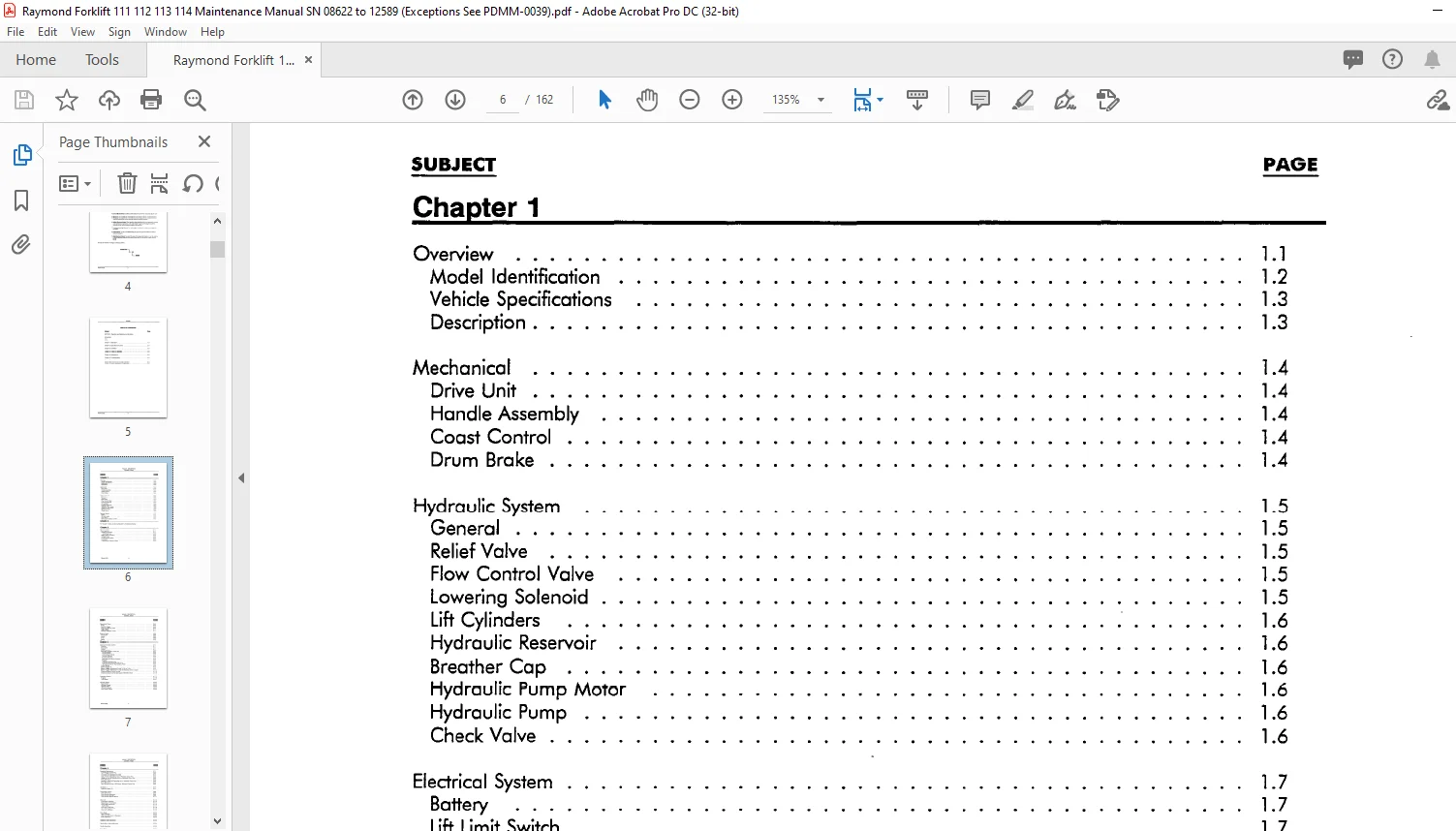
TABLE OF CONTENTS:
Raymond Forklift Walkie 111TM-F60L 112TM-FRE60L 113TM-F60L 114TM/TOW-FRC60L Operation & Maintenance Manual SN 8622 and up – PDF DOWNLOAD
SECTION I: Operation and Maintenance Instructions
Introduction
Safety
Chapter 1 : Description 1 0
Chapter 2: Operating Instructions 2 0
Chapter 3: Installation 3 0
Chapter 4: Theory of Operation 4 0
Chapter 5: Maintenance 5 0
Chapter 6: Troubleshooting 6 0
Chapter 7: Appendix 7 0
Chapter 8: Special Supplement (If Applicable) 8 0
PDMM-0023 111
Chapter 1
Overview
Model Identification
Vehicle Specifications
Description
Mechanical
Drive Unit
Handle Assembly
Coast Control
Drum Brake
Hydraulic System
General
Relief Valve
Flow Control Valve
Lowering Solenoid
Lift Cylinders
Hydraulic Reservoir
Breather Cap
Hydraulic Pump Motor
Hydraulic Pump
Check Valve
Electrical System
Battery
Lift Limit Switch
Drive Motor
Advanced Transistor Control
Chapter 2
WALKIE: DESCRIPTION
GENERAL INDEX
For Chapter 2 index, see Owner/Operator’s Handbook attached
Chapter 3
Visual Inspection
Checking the Battery
Hydrometer Use
Adding Water To Battery
Voltage Check
Connecting the Battery
Lubrication
Checking the Hydraulic System
Operational Checks
Brake
Fork/Lift Linkage
Emergency Reverse Switch
Coast Control
Receiving Inspection Guide
Break-In Period
Introduction
Motors
Pump
Battery
Chapter 4
Advanced Transistor Control
Overview
Presentation
Outline
System Overview
Advanced Transistor Control (AT)
Current Limiting
Undervoltage Cutback
Thermal Protection
Runaway Protection
Static Return to Neutral Protection
Plugging
Controller Keyswitch Input
Controller Thumbwheel Throttle Inputs
“Emergency Reverse” Plug Breaking Inhibit
Control Module
Battery Plugged IN
Battery Plugged IN/Keyswitch Turned To ON or Turtle
Battery Plugged IN/Keyswitch Turned ON/Deadman Switch Closed
Directional/Speed Control Forward
Directional/Speed Control-High Speed (FORWARD ONLY)
Emergency Reverse
Plugging
Turtle Speed
Lift/Lower System
Keyswitch ON
Lift Switch Closed
Hydraulic Action
Lift Switch Opened
Lower Switch Closed
Chapter 5
Scheduled Maintenance
Cold Storage Conditioning
Classes Of Cold Storage
Lubrication and Maintenance Guide
WALKIE: DESCRIPTION
GENERAL INDEX
Daily or Every 8 Operating Hours, Whichever Occurs First
Weekly or Every 50 Operating Hours, Whichever Occurs First
Every 100 Hours
Monthly or Every 200 Operating Hours, Whichever Occurs First
Every 500 Hours
Semi Annually or Every 1,000 Hours, Whichever Occurs First
Lubrication
Hydraulic System Oil
Component Location
Drive Unit Service
Drive Housing Lubrication
Drive Housing Vent Plug
Drive Housing Steering Bearing
Drive Unit
Transmission Assembly
Reassembly of Transmission
Pinion Shaft Disassembly
Tooth Pattern
Drive Gear Case Data
Gear Checking Procedure
Drive Unit Installation
Drum Brake
Daily Inspection
After Every 500 Hours of Operation
Brake Adjustment
Deadman Switch Adjustment
Handle Return Spring Adjustment
Handle Assemblies
Drive Wheel
Daily Inspection
After Every 50 Hours of Operation
After Every 200 Hours of Operation
Cushion Drive Tire Replacement
Load Wheels
Daily Inspection
After Every 50 Hours of Operation
After Every 500 Hours of Operation
Wheel Replacement
Casters
Daily Inspection
Fork And Linkage
After Every 50 Hours of Operation
Fork Height Adjustment
Lowered Fork Height
Lift Limit Switch Adjustment
Hydraulic Maintenance
Inspection Daily
500 Hours
Hydraulic Reservoir
WALKIE: DESCRIPTION
GENERAL INDEX
Checking and Adjusting Hydraulic Pump Relief Valve Pressure
Relief Valve Setting
Hydraulic Reservoir
Inspection Every 8 Hours
Inspection Every 200 Hours
Inspection Every 1 ,000 Hours
Lift Cylinders Service
Oil Leakage Wiper Seal
Electrical Maintenance
Battery Daily Checks
Electrolyte Level
Specific Gravity
The Exterior of the Battery
Battery Charging
Battery Storage
Motor Adjustments and Inspection
Brushes
Commutator
Inspection
Servicing
High Mica
Resurfacing
Drive Motor General Data
Drive Motor Inspection
Drive Motor Removal
Hydraulic Pump Motor General Data
Hydraulic Pump Motor Inspection
Hydraulic Pump Motor Removal
Electrical Maintenance
Electrical System Adjustments
Potentiometer Adjustments
Current Limit Setting
Plug Current Adjustment
Acceleration Adjustment
Potentiometer
Drive Motor Cutout Switch Adjustment
Contactors
Cleaning
Inspection
Contactor Tip Inspection
Contactor Table
Contactor Maintenance
Contactor Coil Replacement
WALKIE: DESCRIPTION
GENERAL INDEX
Replacement Of Contactor Tips, Insulation And/or Core And Rod Assembly
Disassembly/Reassembly
Checking Components
Diodes
Plug Diode Test
Testing Other Electrical Components
Throttle Potentiometer Setting
Turtle Module Replacement
Welding Precautions
Chapter 6
Troubleshooting
Overview
Wiring Inspection Procedure
Truck Does Not Run – Directional Contactors Do Not Close
Truck Does Not Run – Directional Contactors Work Normally
Truck Runs In One Direction – Forward/Reverse Directional Contactor Does Not Close
Truck Runs In One Direction Only – Directional Contactors Work Normally
Truck Does Not Run In High Speed (Forward Only)
Plugging Not Operating Properly
Plugging Too Soft/Too Harsh
Truck Operates, But Does Not Accelerate Properly
Truck Operates Normally, But Emergency Reverse Does Not Engage
Emergency Reverse Engages, But Truck Does Not Travel-(Reverse)
Forks Do Not Lift When Lift Button Is Pushed
Forks Do Not Lower When Lower Button Is Pushed
Chapter 7
Lubrication Equivalency Chart
Standard Torque Data For Bolts
Conversion Table
Decimal Equivalent Chart
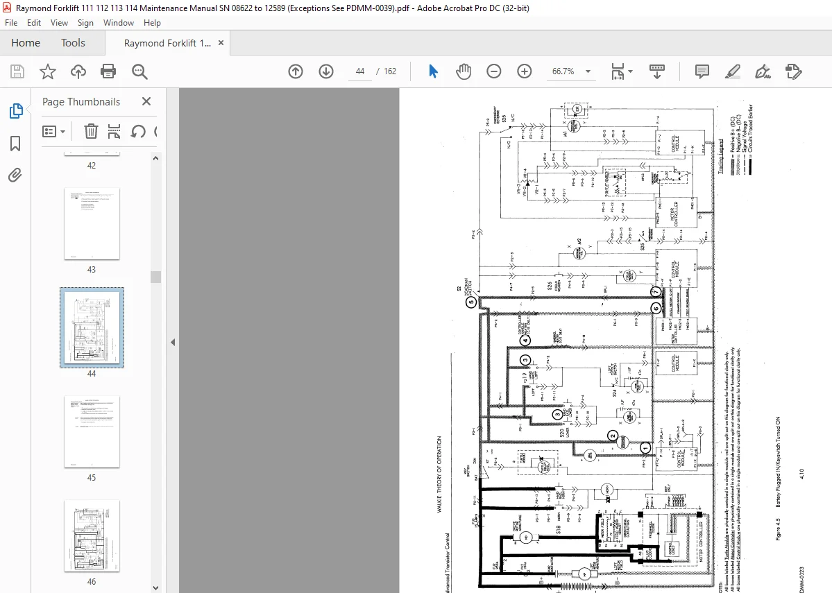
Schematic Legend
Electrical Schematic – Model 111 TM-F60L
Electrical Schematic – Model l l 2TM-FRE60L
Electrical Schematic – Model 113TM-F60L
Electrical Schematic – Model 114TOW-FRC60L
High Power Wiring Schematic for 111TM-F60L
High Power Wiring Schematic for 112TM-FRE60L/1 l 3TM-FRC60L
High Power Wiring Schematic for 114TM-TOW
Hydraulic Schematic
Harness Wiring Test Points
Controller Harness Test Points
Main Wiring Harness Test Points
IMAGES PREVIEW OF THE MANUAL:
Customer Support: [email protected]
https://vimeo.com/836424248?share=copy
PLEASE NOTE:
- This is the SAME manual used by the dealers to troubleshoot any faults in your vehicle. This can be yours in 2 minutes after the payment is made.
- Contact us at [email protected] should you have any queries before your purchase or that you need any other service / repair / parts operators manual.
S.V