Description
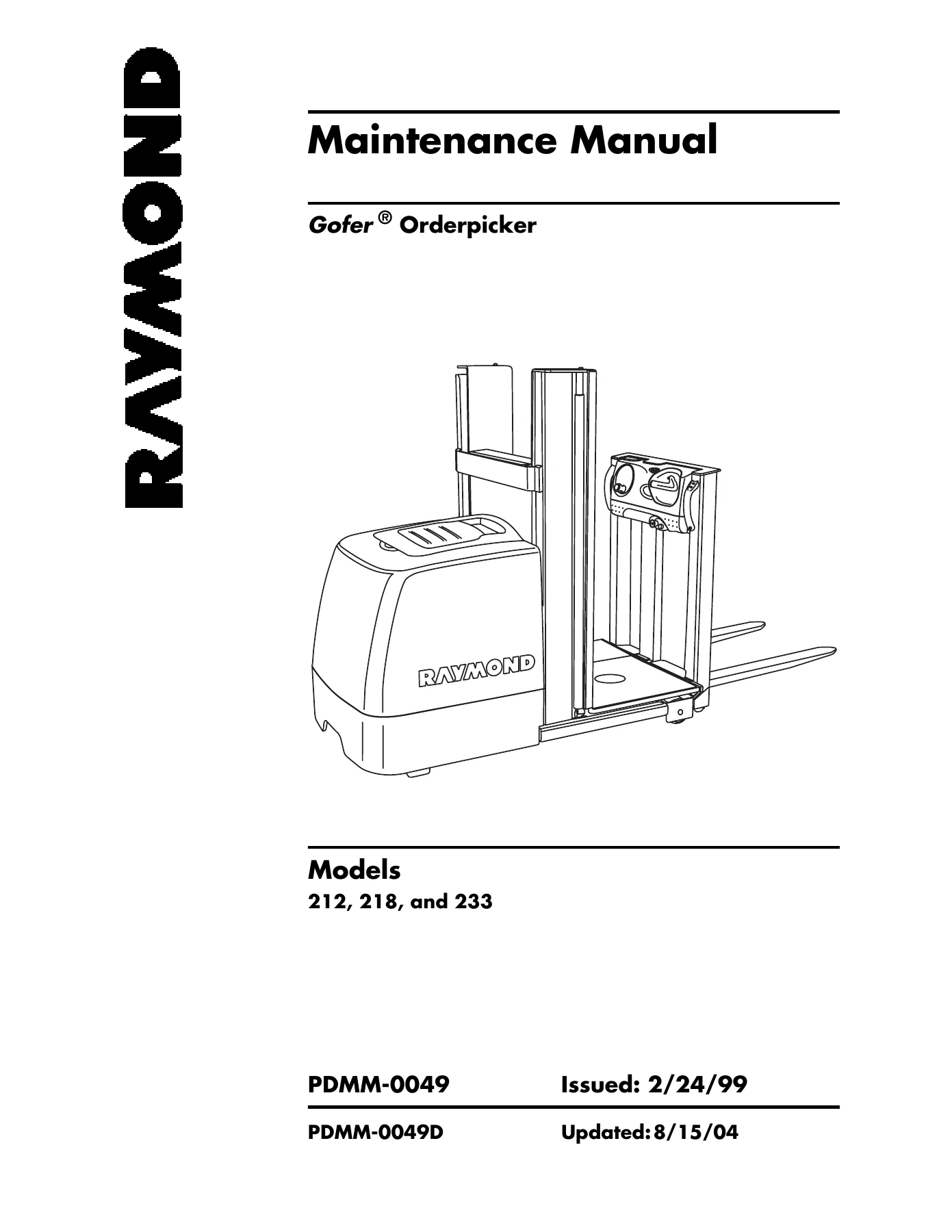
Raymond Gofer 212, 218, and 233 Orderpicker Maintenance Manual
The Raymond Gofer 212 218 233 Orderpicker Maintenance Manual PDMM-0049D is the complete service and maintenance documentation set for these three Raymond Gofer orderpicker models. Published as document PDMM-0049D (Second Edition, updated August 15, 2004), this manual delivers the factory maintenance procedures, system theory, diagnostic fault codes, and component-level repair instructions needed by technicians, fleet maintenance departments, and equipment owners who service these machines.
This is not a generic material handling guide. Every procedure, specification, and troubleshooting chart inside is written specifically for the Raymond Gofer 212, Gofer 218, and Gofer 233 orderpickers. The manual walks through scheduled maintenance intervals, hydraulic and electrical diagnostics, fault code interpretation, component removal and installation, option kit installation, and the operational theory behind each truck system.
File Details
- Manual Type: Maintenance Manual
- Brand: Raymond
- Models Covered: Gofer Orderpicker 212, 218, 233
- Document Number: PDMM-0049D
- Edition: Second Edition
- Revision Date: August 15, 2004 (original issue February 24, 1999)
- Language: English
- File Format: PDF
- Page Count: 440 pages
Chapters Covered
- How To Use This Manual — Manual Design, Map of the Manual, Page Revision Record, Service Bulletins Included, Product Improvement Notices Included
- Safety — Definitions (Warning and Caution), General Safety, Battery Safety, Static Safety, Jacking Safety, Tie-Down for Transport, Towing a Disabled Unit, Welding Safety
- Systems Overview — Vehicle Specifications for Models 212, 218, and 233, Special Tools (Programmable Maintenance Tool, Pin Extractor, PC Loader, Seal Installation Tool, Piston Cap Tool), Cold Storage
- Scheduled Maintenance — Maintenance Guidelines, Operator’s Daily Checklist, Moderate and Severe Usage Intervals (Every 6 Months/500 Hours, Every 3 Months/250 Hours, Every Year/1500 Hours), Lubrication Points
- Troubleshooting — How to Use This Chapter, Electrical Troubleshooting Guidelines, Shorts to Frame Test, Hydraulic Troubleshooting Guidelines, Electrical Connector Locator Chart, Drive Unit Troubleshooting Guide, List of Troubleshooting Charts, Troubleshooting Flowcharts (Hydraulic Charts H-1 through H-5, Travel Charts T-1 through T-11, General Troubleshooting, End of Troubleshooting Procedure)
- Codes and Tests — Operator Display Messages (Steering Indicator, Battery Indicator, Fault Code, Info Display, Battery State of Charge), Maintenance Mode, Traction Power Amplifier Fault Codes, Operator Display Fault Codes (Codes 1,1 through 7,7)
- Component Procedures — Tractor Cover, Finger Guard, Operator Console, Operator Display, Steering Wheel, Steer Encoder, Control Handle, Throttle Potentiometer, Drive Unit, Drive Wheel, Drive Tire, Brake, Brake Air Gap Adjustment, Brake Friction Plate, Battery (without rollers, with rollers, exterior cleaning, charging, adding water, specific gravity, voltage check, maintenance-free, storage), Traction Power Amplifier (cleaning, removal, installation, cloning, programming), Contactors, Contactor Tip Replacement, Fuses, Circuit Cards, Horn, Power Cables, Wiring Harness, Switches (General, Hall Effect, Control Handle, Deadman, Emergency Power Off, Key, Mast, Steer), Motors (General, Brushes, Brush Spring Tension, Commutator, Terminal Nuts, Electric Motor Tests, Grounded Motor Test, Short-Circuited Armature, Drive Motor, Steer Motor, Lift Motor), Hydraulic Components (Hydraulic Fluid, Hydraulic Filter, Hydraulic Assembly, Hydraulic Manifold, Solenoid Valves, Lift Pump, Lift Pressure Adjustment, Bleeding the Hydraulic System), Lift Ram (Models 212/218, Model 233), Flow Control Valve, Lift Ram Seals, Auxiliary Lift, Operator Platform (Models 212/218, Model 233), Mast Cable (Models 212/218, Model 233), Lift Chains, Forks (without mini mast, with mini mast), Load Wheels
- Option Kits — Auxiliary Power Hook-Up, Bin Lights (Models 212, 218, 233 with and without overhead guards), Clipboard, Fan Assembly, Fire Extinguisher, Hour Meter, Lift Limit, Lift Limit With Bypass, Mast Guard, Mini-Lift, Operator Console Mounting, Installing Forks, Adjusting Lift Chains, Adjust Pressure Relief, Overhead Guard-212, Pallet Clamp, Platform Extensions (without mini mast, with mini mast), Rail Guidance — Installing Guide Rollers, Sidegates Without Interlock, Sidegates With Interlock, Sidegate Power Interlock Kit, Storage Caddie, Warning Light
- Theory of Operation — Battery Plugged In, Key Switch On, Closing Deadman Switches, Travel (Moving Directional/Speed Control), Traction Power Amplifier Interface, Steering, Lift/Lower, Auxiliary Lift, Auxiliary Lower, Lower Decel Switch, Decel Top Switch, Lift Limit Switch, Lift Limit Bypass Switch, Pump Contactor Coil Driver, Load Holding Solenoid, Pump Sense
- Software Configuration — PC Loader Program (Overview, Requirements, Installation, Connecting PC to Truck, Starting PC Loader), Troubleshooting, Flash Memory Program, Clear Primary Memory, BSOC Cutout Threshold, Options and Serial Number, Learn Throttle, Diagnostics (Events and Codes, Safety Controls and Gates, Lift, Steering, Travel)
- Appendix — Lubrication Equivalency Chart, Torque Chart – Standard (Ferrous), Torque Chart – Metric, Torque Chart – Standard (Brass), Decimal Equivalent Chart, Standard/Metric Conversions, Electrical Schematic, Hydraulic Schematic
- Index — Alphabetical subject index
Complete PDF Bookmark Tree
Complete Bookmarks
The complete bookmarks in the “Raymond Gofer 212 218 233 Orderpicker Maintenance Manual PDMM-0049D” are as follows:
Table of Contentsp. 13
+How To Use This Manualp. 3
Map of the Manualp. 4
Manual Designp. 6
Page Revision Recordp. 9
Service Bulletins Includedp. 11
Product Improvement Notices Includedp. 11
Table of Contentsp. 13
START Pagep. 17
+Safetyp. 19
Definitionsp. 20
General Safetyp. 21
+Battery Safetyp. 25
Figure 2-1: ESD Plug On Tractorp. 30
+Static Safetyp. 30
Figure 2-2: ESD Plug on Operator Consolep. 30
Figure 2-3: Anti-Static Kit (P/N 1-187-059) With Wrist Strap and Matp. 31
Figure 2-4: Operator Platform Blocking Point For Safety Standp. 32
+Jacking Safetyp. 32
Figure 2-5: Operator Platform Blocking Point For Blockp. 32
+Operator Platformp. 32
Figure 2-6: Tractor Jacking Pointsp. 33
+Tractorp. 33
Figure 2-7: Baseleg Jacking Pointsp. 33
Baselegp. 33
+Tie-Down for Transportp. 34
Figure 2-8: Tie-down for Transportp. 34
Towing a Disabled Unitp. 35
Welding Safetyp. 36
+Systems Overviewp. 39
Vehicle Specificationp. 40
+Special Toolsp. 42
Figure 3-1: Programmable Maintenance Toolp. 42
+Programmable Maintenance Toolp. 42
Figure 3-2: Pin Extractorp. 42
Pin Extractorp. 42
+PC Loaderp. 42
Figure 3-3: Seal Installation Toolp. 43
+Seal Installation Toolp. 43
Figure 3-4: Piston Cap Toolp. 43
Piston Cap Toolp. 43
+Cold Storagep. 44
Figure 3-5: Cold Storage Electrical Schematicp. 45
+Scheduled Maintenancep. 47
Maintenance Guidelinesp. 48
Operator’s Daily Checklistp. 49
Moderate Usage: Every 6 Months or 500 Hours; Severe Usage: Every 3 Months or 250 Hoursp. 50
Moderate and Severe Usage: Every Year or 1500 Operating Hoursp. 53
+Lubrication Pointsp. 54
Figure 4-1: Grease Fittings on Drive Unitp. 54
Figure 4-2: Mast Lubrication Pointsp. 54
+Troubleshootingp. 55
How to Use This Chapterp. 56
Electrical Troubleshooting Guidelinesp. 57
Shorts to Frame Testp. 58
Hydraulic Troubleshooting Guidelinesp. 64
Definitionsp. 65
+Electrical Connector Locator Chartp. 67
Table 5-1:� Electrical Connector Locator Chartp. 67
+Programmable Maintenance Toolp. 69
Figure 5-1: Programmable Maintenance Toolp. 69
Figure 5-2: Connection for PMT to Traction Power Amplifierp. 69
Diagnostic Historyp. 69
+Test Modep. 70
Table 5-2:� Test Modep. 71
Table 5-3:� Modes of Operationp. 71
Table 5-4:� Diagnostics and Special Diagnostics Listp. 72
+Special Program Modep. 73
Table 5-5:� Special Program Modep. 73
+Programmingp. 74
Table 5-6:� Traction Power Amplifier Parametersp. 75
Drive Unit Troubleshooting Guidep. 76
+List of Troubleshooting Chartsp. 77
Hydraulic Chartsp. 77
Travel Chartsp. 77
Troubleshooting Flowchartsp. 79
+Codes and Testsp. 125
+Operator Display Messagesp. 126
Figure 6-1: Operator Displayp. 126
Table 6-1:� Steering Indicator Display Messagesp. 126
Steering Indicator Messagesp. 126
+Battery Indicator Messagesp. 127
Table 6-2:� Battery Indicator Messagesp. 127
Table 6-3:� Info Display Messagesp. 128
Figure 6-2: Battery State of Chargep. 128
+Maintenance Modep. 129
Table 6-4:� Steer Encoder Test Resultsp. 131
+Traction Power Amplifier Fault Codesp. 132
Figure 6-3: Traction Power Amplifier LEDp. 132
+Operator Display Fault Codesp. 133
Code 1,1p. 133
Code 1,2p. 134
Code 1,3p. 135
Code 1,4p. 136
Code 1,5p. 137
Code 1,6p. 138
Code 2,1p. 140
Code 2,2p. 141
Code 2,3p. 142
Code 2,4p. 144
Code 3,1p. 145
Code 3,2p. 146
Code 3,3p. 147
Code 3,4p. 148
Code 3,5p. 149
Code 4,1p. 150
Code 4,2p. 152
Code 4,3p. 153
Code 4,4p. 154
+Code 4,6p. 155
Figure 6-4: Circuit Card Transmit/Receive Diagramp. 155
Code 5,1p. 156
Code 5,2p. 158
Code 5,3p. 159
Code 5,4p. 161
Code 5,5p. 162
Codes 7,2; 7,4; 7,5; 7,6; 7,7p. 163
Electrical System Troubleshooting – Carriage Managerp. 164
+Component Proceduresp. 165
+List of Component Proceduresp. 166
Ap. 166
Bp. 166
Cp. 166
Dp. 166
Ep. 166
Fp. 166
Gp. 166
Hp. 166
Lp. 166
Mp. 167
Op. 167
Pp. 167
Rp. 167
Sp. 167
Tp. 167
Vp. 168
Wp. 168
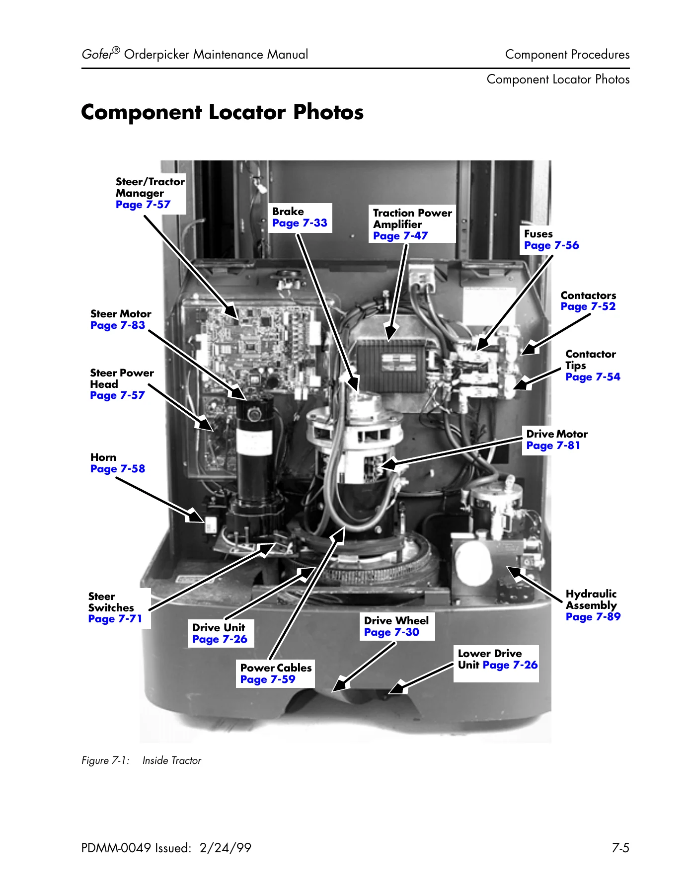
+Component Locator Photosp. 169
Figure 7-1: Inside Tractorp. 169
Figure 7-2: Hydraulic Componentsp. 170
Figure 7-3: Mast Switch Locationsp. 171
Figure 7-4: Tractor Viewp. 172
Figure 7-5: LEDs IL1—IL4 on Carriage Managerp. 173
Figure 7-6: LEDs IL1—IL6 On Steer/Tractor Managerp. 174
Figure 7-7: LEDs IL 7 and IL8 on Steer/Tractor Managerp. 175
Figure 7-8: LEDs IL9 and IL10 on Steer/Tractor Managerp. 176
Figure 7-9: LED IL1 on Steer Power Headp. 177
Figure 7-10: Unlatching the Tractor Coverp. 178
+For Models Below S/N 233-00-02220:p. 178
Figure 7-11: Hand-hold in Top of the Tractor Coverp. 178
Figure 7-12: Handling the Tractor Coverp. 178
Figure 7-13: Fitting the Tractor Cover Around the Tractorp. 179
Figure 7-14: Fitting the Tractor Cover In the Sides of the Cover Retainersp. 179
Figure 7-15: Fitting the Tractor Cover In the Top of the Cover Retainerp. 180
Figure 7-16: Latching the Tractor Cover In the Mounting Brackets.p. 180
+For Models Above S/N 233-00-02220:p. 181
Figure 7-16.1: Opening the Tractor Coverp. 181
Figure 7-16.2: Tractor Cover Opened For Battery Accessp. 181
Figure 7-16.3: Tractor Cover Removedp. 181
Figure 7-16.4: Installing Tractor Coverp. 182
Figure 7-16.5: Cover Installation Detailp. 182
Figure 7-16.6: Closing Tractor Coverp. 182
Figure 7-17: Finger Guardp. 183
+Finger Guardp. 183
Figure 7-18: Adjusting the Operator Console Positionp. 184
Figure 7-19: Removing Operator Console Coversp. 184
Figure 7-20: Jumper E1 Locationp. 185
Figure 7-21: Replacing Operator Displayp. 186
+Operator Displayp. 186
Figure 7-22: Removing Slack in Connector Ribbonp. 186
Figure 7-23: Removing Snap Ring on Steering Wheel Shaft (Top View)p. 187
+Steering Wheelp. 187
Figure 7-24: Replacing Steering Wheelp. 187
Figure 7-25: Hardware on Steering Wheel Shaftp. 187
Figure 7-26: Sliding Steer Encoder off Steering Wheel Shaft (Top View)p. 188
+Steer Encoderp. 188
Figure 7-27: Disconnecting ENC at the Encoder Housingp. 188
Figure 7-28: Installing Steer Encoderp. 188
Figure 7-29: Removing the Snap Ringp. 189
+Control Handlep. 189
Figure 7-30: Removing Control Handlep. 189
Figure 7-31: Installing Control Handle, Return Spring Insertedp. 189
+Throttle Potentiometerp. 190
Figure 7-32: Sliding Throttle Potentiometer Off Control Handle Bracketp. 191
Figure 7-33: Drive Unit Mounting Bolts, Three Hiddenp. 192
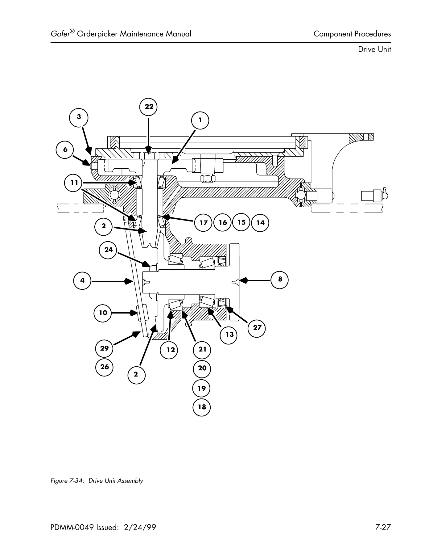
Figure 7-34: Drive Unit Assemblyp. 193
+Drive Wheelp. 196
Figure 7-35: Drive Wheel Mounting Boltsp. 196
Figure 7-36: Drive Tire Installationp. 197
+Brakep. 199
Figure 7-37: Removing the Brake Assemblyp. 200
Figure 7-38: Brake Assemblyp. 201
Figure 7-39: Top View of Drive Motor, Brake Removedp. 201
Figure 7-40: Installing the Brake Assemblyp. 202
Figure 7-41: Measuring Brake Air Gapp. 203
+Brake Air Gap Adjustmentp. 203
Figure 7-42: Brake Assembly Componentsp. 203
+Brake Friction Plate (Rotor)p. 203
Figure 7-43: Disassembling the Brakep. 204
Figure 7-44: Brake Assembly Componentsp. 204
+Without Battery Rollersp. 205
Figure 7-45: Battery Removal/Installationp. 205
+With Battery Rollersp. 206
Figure 7-46: Battery Filler Plugs and Vent Holesp. 207
Battery Exterior Cleaningp. 207
Chargingp. 208
Adding Waterp. 210
Specific Gravityp. 211
Voltage Checkp. 212
Maintenance Free Batteriesp. 212
+Storagep. 212
Figure 7-47: Traction Power Amplifierp. 213
+Traction Power Amplifierp. 213
Figure 7-48: Disconnecting Wires and Cablesp. 214
Figure 7-49: Bus Bar Connections on Traction Power Amplifierp. 214
Figure 7-50: Traction Power Amplifier Mounting Hardwarep. 214
Figure 7-51: Connection for PMT to the Traction Power Amplifierp. 215
Table 7-1:� Traction Power Amplifier Parametersp. 217
+Contactorsp. 218
Figure 7-52: Severely Pitted Contactorp. 218
Figure 7-53: Disconnecting Cables and Fuses (Equipped with Auxiliary Lift)p. 219
Figure 7-54: Removing Bus Bars (Equipped with Auxiliary Lift)p. 219
Figure 7-55: Removing Hex Nuts (Equipped with Auxiliary Lift)p. 219
Figure 7-56: Contactor Componentsp. 220
+Contactor Tip Replacementp. 220
Figure 7-57: Pump Contactor Componentsp. 220
Figure 7-58: Installing New Contactor Componentsp. 221
Figure 7-59: Contactor Assemblyp. 221
Figure 7-60: Fuse Locationsp. 222
+Fusesp. 222
Figure 7-61: Control Fuses on Steer/Tractor Managerp. 222
Figure 7-62: Circuit Cards in Tractorp. 223
+Circuit Cards (General)p. 223
Figure 7-63: Carriage Manager in Operator Consolep. 223
Figure 7-64: Horn Locationp. 224
Hornp. 224
Power Cablesp. 225
Wiring Harnessp. 226
+Switches (General)p. 229
Figure 7-65: Hall Effect Switch Schematicp. 229
+Hall Effect Switchesp. 229
Figure 7-66: Typical Hall Effect Switchp. 229
Figure 7-67: Removing Wires with Pin Extractorp. 230
+Control Handle Switchesp. 230
Figure 7-68: Prying Switch from Control Handlep. 230
Figure 7-69: Tubes for Switch Cable Pairsp. 230
Figure 7-70: Deadman Pedal Post Under Platformp. 231
+Deadman Switchesp. 231
Figure 7-71: Removing/Installing the Deadman Pedalp. 231
Figure 7-72: Deadman Switchesp. 231
Figure 7-73: Backside of the EPO Switchp. 232
+Emergency Power Off Switchp. 232
Figure 7-74: Unlocking the Halves of the EPO Switchp. 232
Figure 7-75: Separated Halves of the EPO Switchp. 232
Figure 7-76: Mounting Nut Locationp. 233
+Key Switchp. 233
Figure 7-77: Replacing the Key Switchp. 233
Figure 7-78: S6 and S7 Location, Models 212 and 218p. 234
+Mast Switchesp. 234
Figure 7-79: S6 and S7 Location, Model 233p. 234
Figure 7-80: S22 Location, Models 212, 218p. 234
Figure 7-81: S22, S25 and S29 Location, Model 233p. 235
Figure 7-82: Steering Position Rangesp. 235
Figure 7-83: Switch Mounting, Model 212 Shownp. 236
Figure 7-84: Separating Switch Housingp. 236
Figure 7-85: Removing Nuts from Mounting Screwsp. 237
+Steer Switchesp. 237
Figure 7-86: Removing Mounting Screwsp. 237
Figure 7-87: Separating Switch Housingp. 237
+Motors (General)p. 239
Figure 7-65: Motor Brush Locationp. 239
Motor Brushesp. 239
+Motor Brush Spring Tensionp. 241
Figure 7-66: Motor Brush Spring Tension Inspectionp. 241
+Commutatorp. 242
Figure 7-67: Motor Terminal – Double Nutp. 243
+Terminal Nutsp. 243
Figure 7-68: Motor Terminal – Triple Nutp. 243
+Electric Motor Testsp. 244
Figure 7-69: Motor Circuitsp. 244
Motor Typesp. 244
Open Circuit Motor Testp. 244
Grounded Motor Testp. 245
+Short-Circuited Armature or Field Windingp. 246
Figure 7-70: Removing the Switch Railp. 247
+Drive Motorp. 247
Figure 7-71: Breaking the Drive Unit Sealp. 247
Figure 7-72: Removed Drive Motor, Bottom View of End Bellp. 247
Figure 7-73: Installing Switch Railp. 248
Figure 7-74: Checking Gear Oil Levelp. 248
Figure 7-75: Steer Motor Locationp. 249
+Steer Motorp. 249
Figure 7-76: Steer Motor Assemblyp. 249
Figure 7-77: Gear End of Removed Steer Motor Assemblyp. 250
Figure 7-78: Disassembled Steer Motor Assemblyp. 250
Figure 7-79: Lift Motor Mountingp. 251
+Lift Motorp. 251
Figure 7-80: Replacing Lift Motorp. 251
Figure 7-81: Drain Plugp. 252
Figure 7-82: Filling the Hydraulic Reservoirp. 252
Figure 7-83: Hydraulic Filter Locationp. 254
+Hydraulic Filterp. 254
Figure 7-84: Hydraulic Fluid Filterp. 254
Figure 7-85: Hydraulic Assembly Componentsp. 255
+Hydraulic Assemblyp. 255
Figure 7-86: Hydraulic Line Connectionsp. 255
Figure 7-87: Hex Head Cap Screws, Four Shownp. 256
Figure 7-88: Hydraulic Assembly, Removedp. 256
Figure 7-89: Electric Connections To Hydraulic Assemblyp. 257
Figure 7-90: Hydraulic Manifold, Removedp. 258
+Hydraulic Manifoldp. 258
Figure 7-91: Solenoid Valvesp. 259
+Solenoid Valvesp. 259
Figure 7-92: Removing the Solenoid Coil From Valve Barrelp. 259
Figure 7-93: Removing the Valve Barrelp. 260
Figure 7-94: Installing the Valve Barrelp. 260
Figure 7-95: Hydraulic Assembly, Removedp. 261
+Lift Pumpp. 261
Figure 7-96: Pump Mounting and Hydraulic Assembly Platep. 261
Figure 7-97: Installing New Pumpp. 261
Figure 7-98: Adjusting the Lift Pressurep. 262
+Lift Pressure Adjustmentp. 262
Figure 7-99: Bleed Screw Locationp. 263
+Bleeding the Hydraulic Systemp. 263
+Noisy Lift Ram Sealsp. 263
Figure 7-100: Removing the Spring Clip from the Pistonp. 264
+Lift Ram— Models 212 and 218p. 264
Figure 7-101: Removing the Mast Cable Bracketp. 264
Figure 7-102: Disconnecting the Mast Cablep. 265
Figure 7-103: Removing Cable from Racewayp. 265
Figure 7-104: Removing the Flair Fittingp. 266
Figure 7-105: Removing the Mounting Boltp. 266
Figure 7-106: Installing Self-Aligning Bushingsp. 266
Figure 7-107: Tightening the Flair Fittingp. 267
Figure 7-108: Placing Cable in Racewayp. 267
Figure 7-109: Fitting Pistons into Mounting Holesp. 268
Figure 7-110: Carriage Chain Anchor (One Shown), Underside of Platformp. 269
+Lift Ram—Model 233p. 269
Figure 7-111: Main Channel Chain Anchor (2)p. 269
Figure 7-112: Removing Screw from Top of Pistonp. 270
Figure 7-113: Removing the Flair Fittingp. 270
Figure 7-114: Removing Mounting Boltp. 271
Figure 7-115: Ram Retainer Boltp. 271
Figure 7-116: Installing Self-Aligning Bushingsp. 272
Figure 7-117: Installing Screw to Top of Pistonp. 272
Figure 7-118: Connecting Hydraulic Linep. 273
Figure 7-119: Feeding Cable Through Pathway from Baselegp. 273
Figure 7-120: Feeding Cable Through Pathwayp. 273
Figure 7-121: Carriage Chain Anchorp. 274
Figure 7-122: Main Channel Chain Anchorp. 274
Figure 7-123: Replacing the Flow Control Valvep. 275
+Flow Control Valvep. 275
Figure 7-124: Loosening the Gland Nutp. 276
+Lift Ram Sealsp. 276
Figure 7-125: Pulling the Piston Out of the Cylinderp. 276
Figure 7-126: Seal Installation Toolp. 276
Figure 7-127: Seals in the Gland Nutp. 277
+Auxiliary Liftp. 278
Figure 7-128: Jumper E1 on Carriage Managerp. 278
Figure 7-129: Auxiliary Manifoldp. 278
Figure 7-130: Removing Snap Rings from Pistonsp. 279
Figure 7-131: Removing Stop Screws from Mast Channelp. 279
Figure 7-132: Mounting/Shimming Bearing Boss To Uprightp. 280
Figure 7-133: Carriage Chain Anchor (2), Underside of Platformp. 281
+Operator Platform—233p. 281
Figure 7-134: Main Channel Chain Anchor (2)p. 281
Figure 7-135: Cable Chains under Platformp. 282
Figure 7-136: Cable Chain under Platformp. 282
Figure 7-137: Access to Cable Pathway from Tractorp. 282
Figure 7-138: Cable Chain on Outside Carriagep. 283
Figure 7-139: Removing Operator Platform from Truckp. 283
Figure 7-140: Cable Pathway Access from Baselegp. 284
Figure 7-141: Realigning Cables in Pathwayp. 284
Figure 7-142: Carriage Chain Anchorp. 284
Figure 7-143: Main Channel Chain Anchor (2)p. 285
Figure 7-144: Main Channel Chain Anchorp. 286
+Lift Chains—Model 233p. 286
Figure 7-145: Carriage Chain Anchor (One Shown), Underside of Platformp. 287
Figure 7-146: Main Channel Chain Anchor (One shown)p. 287
Figure 7-147: Unbolting the Forksp. 288
+Forks—Without Mini Mastp. 288
Figure 7-148: Snap Ring, Pivot Pin and Mounting Bossp. 288
Figure 7-149: Driving Out Pivot Pinp. 288
Figure 7-150: Installing the Forks and Shimsp. 289
Figure 7-151: Components of the Fork Carriagep. 290
+Forks—With Mini Mastp. 290
+Removep. 290
Figure 7-152: Fork Mounted On the Fork Carriagep. 290
+Installp. 290
Figure 7-153: Bleeding the Auxiliary Lift Systemp. 290
Figure 7-154: Blocking Platform and Jacking Base Legp. 291
+Load Wheelsp. 291
Figure 7-155: Load Wheel Componentsp. 291
Figure 7-156: Driving Out the Axlep. 292
Figure 7-157: Replacing Load Wheel Assemblyp. 292
Figure 7-158: Securing the Axlep. 292
Figure 7-159: Disconnecting the Mast Cablep. 293
+Mast Cable— Models 212 and 218p. 293
Figure 7-160: Disconnecting Mast Cable Bracketp. 293
Figure 7-161: Removing Cable from Racewayp. 294
Figure 7-162: Mast Cable Connection to Carriage Managerp. 295
+Mast Cable—Model 233p. 295
Figure 7-163: Removing Cable Chainsp. 295
Figure 7-164: Removing Cable Chainsp. 295
Figure 7-165: Access to Cable Pathway Under Platformp. 296
Figure 7-166: Realigning Cables in Pathwayp. 296
Figure 7-167: Installing Cable Chainsp. 297
Figure 7-168: Installing Cable Chainsp. 297
Figure 7-169: Mast Cable Routing On Operator Platformp. 298
+Option Kitsp. 299
Figure 8-1: Cross-tie Locationp. 300
+Auxiliary Power Hook-Upp. 300
Figure 8-2: Detail Ap. 300
Figure 8-3: Operator Console Assembly, Back Viewp. 300
Figure 8-4: Operator Console Assembly, Front Viewp. 301
Figure 8-5: Operator Platform, Top Viewp. 301
Figure 8-6: Auxiliary Power Schematicp. 301
Figure 8-7: Bin Light Location and Cable Routingp. 302
+Bin Lightsp. 302
Figure 8-8: View Ap. 302
Figure 8-9: View Bp. 303
Figure 8-10: Bin Light Power Connectionp. 303
Figure 8-11: Model 233, Tractor Sidep. 304
+Bin Lightsp. 304
Figure 8-12: View Bp. 304
Figure 8-13: Bin Light Installationp. 305
Figure 8-14: Clipboard Installationp. 306
+Clipboardp. 306
Figure 8-15: View Ap. 306
Figure 8-16: Fan Assembly Locationp. 307
+Fan Assemblyp. 307
Figure 8-17: Detail Ap. 307
Figure 8-18: Fan Assembly Installationp. 308
Figure 8-19: Fan Locationp. 309
+Fan Assemblyp. 309
Figure 8-20: View Ap. 309
Figure 8-21: Fan Installationp. 310
Figure 8-22: Fire Extinguisher Installationp. 311
+Fire Extinguisherp. 311
Figure 8-23: Hour Meter Installationp. 312
+Hour Meterp. 312
Figure 8-24: Hour Meter Connectionsp. 312
Figure 8-25: Hour Meter Mountingp. 312
Figure 8-26: Lift Limit Switch Locationp. 313
+Lift Limitp. 313
Figure 8-27: View Ap. 313
Figure 8-28: View Bp. 314
Figure 8-29: Operator Consolep. 315
+Lift Limit With Bypassp. 315
Figure 8-30: Bypass Switch Locationp. 315
Figure 8-31: Mounting Location of Mast Guardp. 316
+Mast Guardp. 316
Figure 8-32: Mounting Close-upp. 316
Figure 8-33: Preparing the Mini Mast for Installationp. 317
+Mini-Liftp. 317
Figure 8-34: Aligning the Mini Mast with the Platformp. 317
Figure 8-35: Cable Locationp. 317
Figure 8-36: Mounting Holesp. 318
Figure 8-37: Installing Mounting Boltsp. 318
Figure 8-38: Mounting the Mini Mast Legs Under Platformp. 318
Figure 8-39: Installing M10 Mounting Boltsp. 319
Figure 8-40: Mini Mast Cable Routingp. 319
Figure 8-41: Cable Connectionsp. 319
Figure 8-42: Auxiliary Power Hook-upp. 320
Figure 8-43: View A-Ap. 320
Figure 8-44: Steering Direction Jumper on Carriage Managerp. 321
+Operator Console Mountingp. 321
Figure 8-45: Preparing Fork Carriage on Mini Mastp. 322
+Installing Forksp. 322
Figure 8-46: Installing Forks on Fork Carriagep. 322
Figure 8-47: Bleed Screw on Auxiliary Lift Systemp. 322
Figure 8-48: Lift Chain Anchor (4), Shown With Finger Guard Removedp. 323
+Adjusting Lift Chainsp. 323
Figure 8-49: Auxiliary Lift Manifoldp. 324
+Adjust Pressure Reliefp. 324
Figure 8-50: Detail Ap. 325
+Overhead Guard—212p. 325
Figure 8-51: View Bp. 325
Figure 8-52: Overhead Guard Locationp. 325
Figure 8-53: Operator Platform, Bottom Viewp. 326
+Pallet Clampp. 326
Figure 8-54: Operator Platform, Side Viewp. 326
Figure 8-55: Detail Ap. 326
Figure 8-56: Detail Cp. 327
Figure 8-57: Detail Ap. 327
Figure 8-58: Platform Extensions, Shown Without Mini Mastp. 328
+Platform Extensionsp. 328
+Without Mini Mastp. 328
Figure 8-59: View A, Without Mini Mastp. 328
Figure 8-60: Details C, D and Ep. 329
+With Mini Mastp. 329
Figure 8-61: View A, With Mini Mastp. 329
+Rail Guidance— Installing Guide Rollersp. 330
Figure 8-62: Mounting Plate Locationsp. 331
Figure 8-63: View Ap. 331
Figure 8-64: Guide Roller Widthp. 332
Figure 8-65: Wheel Mounting Platep. 332
Figure 8-66: Sidegate Assembly Mountingp. 333
+Sidegates Without Interlockp. 333
Figure 8-67: Sidegate Location and Cable Routingp. 334
+Sidegates With Interlockp. 334
Figure 8-68: Sidegate Interlock Switch Installationp. 334
Figure 8-69: Sidegate Location and Cable Routingp. 335
+Sidegate Power Interlock Kitp. 335
Figure 8-70: Installing Sidegate Interlock Switchp. 335
Figure 8-71: Storage Caddie Installationp. 337
+Storage Caddiep. 337
Figure 8-72: Warning Light Location and Cable Routingp. 338
+Warning Lightp. 338
Figure 8-73: Mounting Warning Lightp. 338
Figure 8-74: Detail Ap. 339
Figure 8-75: Warning Light Schematicp. 339
+Theory of Operationp. 341
+Battery Plugged Inp. 342
Figure 9-1: Electrical Schematic Legend (Sheet 1 of 2)p. 344
Figure 9-2: Battery Plugged In (Sheet 1 of 2)p. 346
+Key Switch (S1) Onp. 348
Figure 9-3: Battery Plugged In; Key Switch On (Sheet 1 of 2)p. 350
+Closing Deadman Switches (S2 and S23)p. 352
Figure 9-4: Deadman Switch Pressed (Sheet 1 of 2)p. 354
+Travelp. 356
Generalp. 356
+Moving Directional/Speed Controlp. 356
Figure 9-5: Travel (Sheet 1 of 2)p. 360
Traction Power Amplifier Interfacep. 362
Deadmanp. 362
+Steeringp. 363
Table 9-1:� Steering Indicator Display Messagesp. 364
Figure 9-6: Steering (Sheet 1 of 2)p. 366
+Lift/Lowerp. 368
+Lift (S5)p. 368
Figure 9-7: LEDs IL1-IL6 on Steer/Tractor Controllerp. 370
Figure 9-8: Lift (Sheet 1 of 2)p. 372
Figure 9-9: Liftp. 374
+Lower (S4)p. 375
Figure 9-10: Lower (Sheet 1 of 2)p. 376
Figure 9-11: Lowerp. 378
+Auxiliary Liftp. 379
Figure 9-12: Auxiliary Lift (Sheet 1 of 2)p. 380
+Auxiliary Lowerp. 382
Figure 9-13: Auxiliary Lower (Sheet 1 of 2)p. 384
Lower Decel Switch (S6)p. 386
Decel Top Switch (S22)p. 386
Lift Limit Switch (S24) (Optional)p. 386
Lift Limit Bypass Switch (S51) (Optional)p. 386
Pump Contactor Coil Driverp. 386
Load Holding Solenoidp. 386
Pump Sensep. 387
+Software Configurationp. 389
+PC Loader Programp. 390
Overviewp. 390
Requirementsp. 390
Install PC Loaderp. 390
Connect PC To Truckp. 391
+Start PC Loaderp. 392
Figure 10-1: Main Menu Screenp. 392
+Troubleshootingp. 393
Figure 10-2: Communication Error Screen, at Start-Upp. 393
Figure 10-3: Truck Not Recognized Screenp. 394
Figure 10-4: Communication Error Screen, During Regular Usep. 394
Figure 10-5: Dealer Mismatch Screenp. 395
+Flash Memory Programp. 396
Figure 10-6: Main Menu Screenp. 396
Figure 10-7: Flash Programming Screenp. 396
+Clear Primary Memoryp. 397
Figure 10-8: Main Menu Screenp. 397
Figure 10-9: Clear Primary Memory Screenp. 398
Figure 10-10: Clear Primary Memory Screenp. 398
+BSOC Cutout Thresholdp. 399
Figure 10-11: Main Menu Screenp. 399
Figure 10-12: Lift Cutout Thresholdp. 399
BSOC Cutout Thresholdp. 400
+Options and Serial Numberp. 400
Figure 10-13: Main Menu Screenp. 400
Figure 10-14: Options Menu Screenp. 401
Figure 10-15: Changing Truck Heightp. 401
Figure 10-16: Writing Changes to Truck Softwarep. 402
Figure 10-17: Changing Optionsp. 402
Figure 10-18: Writing Changes to Truck Softwarep. 403
+Learn Throttlep. 403
Figure 10-19: Main Menu Screenp. 403
Figure 10-20: Learn Parameters Screenp. 404
+Diagnosticsp. 404
Figure 10-21: Main Menu Screenp. 405
Figure 10-22: Diagnostics Menu Screenp. 405
Figure 10-23: Active Events Screenp. 406
Figure 10-24: Gofer Diagnostics Menup. 406
Figure 10-25: Safety Diagnostics Screenp. 407
Figure 10-26: Gofer Diagnostics Menup. 408
Figure 10-27: Lift Diagnostics Screenp. 408
Figure 10-28: Gofer Diagnostics Menup. 409
Figure 10-29: Steer Diagnostics Screenp. 409
Figure 10-30: Gofer Diagnostics Menup. 410
Figure 10-31: Traction Diagnostics Screenp. 410
+Appendixp. 411
+Lubrication Equivalency Chartp. 412
Figure 11-1: Lubrication Equivalency Chartp. 412
+Torque Chart – Standard (Ferrous)p. 415
Figure 11-2: Torque Chart – Standardp. 415
+Torque Chart – Metricp. 416
Figure 11-3: Torque Chart – Ferrous Metricp. 416
Figure 11-4: Torque Chart – Brass Metricp. 416
+Torque Chart – Standard (Brass)p. 417
Figure 11-5: Torque Chart – Standard Brassp. 417
+Decimal Equivalent Chartp. 418
Figure 11-6: Decimal Equivalent Chartp. 418
Standard/Metric Conversionsp. 420
+Electrical Schematicp. 423
Figure 11-7: Electrical Schematic, Sheet 1 of 2 Scale=94.5p. 424
Figure 11-8: Legend, Sheet 1 of 2 Scale=108p. 428
+Hydraulic Schematicp. 430
Figure 11-9: Hydraulic Schematic, Sheet 1 of 1p. 430
Indexp. 431
What This Manual Gives You
The Raymond Gofer 212 218 233 Orderpicker Maintenance Manual is structured as a complete maintenance and repair resource. It opens with safety information and system specifications, moves through scheduled maintenance and troubleshooting, then provides detailed component-level procedures with step-by-step instructions, torque values, and illustrations. The troubleshooting chapter uses decision-tree flowcharts that guide you from a symptom to a specific test sequence, and the codes chapter explains every operator display fault code with corrective actions. The theory of operation chapter traces electrical and hydraulic circuits step-by-step so you understand not just what to do, but why.
With 440 pages and coverage of every major system — traction, steering, lift, hydraulic, electrical, and optional equipment — this manual supports the full range of maintenance tasks, from daily inspections and lubrication to drive unit removal and brake disassembly.
Why It Matters
Raymond Gofer orderpickers are precision material handling machines. Using correct procedures and factory specifications is critical for safety, equipment longevity, and avoiding costly downtime. This manual gives you the exact maintenance intervals, torque values, fault code diagnostics, and component specifications that these trucks require. Whether you are performing scheduled maintenance, diagnosing an electrical fault, rebuilding a drive unit, or installing an option kit, the answers are here.
Delivery
This Raymond Gofer Orderpicker maintenance manual is delivered as an instant PDF download. No shipping, no waiting. The file works on any device — laptop, tablet, or smartphone — and every page is printable for use in the shop or service truck.

Reviews
There are no reviews yet.