Raymond Walkie 102XM Maintenance Manual SN 102-03-00500 and up – PDF DOWNLOAD
Original price was: $75.95.$28.95Current price is: $28.95.
Raymond Walkie 102XM Maintenance Manual SN 102-03-00500 and up – PDF DOWNLOAD
Description
Raymond Walkie 102XM Maintenance Manual SN 102-03-00500 and up – PDF DOWNLOAD
FILE DETAILS:
Raymond Walkie 102XM Maintenance Manual SN 102-03-00500 and up – PDF DOWNLOAD
Language : English
Pages : 244
Downloadable : Yes
File Type : PDF
TABLE OF CONTENTS:
Raymond Walkie 102XM Maintenance Manual SN 102-03-00500 and up – PDF DOWNLOAD
Page Revision Recordxi
Document Revision History xi
List of Revised Pagesxi
Service Bulletins and Service Information Documents Includedxii
Product Improvement Notices Includedxiii
How To Use This Manual 1-1
Manual Design 1-2
Interactive Electronic Technical Manuals 1-3
Abbreviations & Symbols 1-4
Safety2-1
Definitions2-2
General Safety2-3
Battery Safety 2-6
Jacking Safety2-9
Fork Section 2-9
Tractor Section2-9
Towing 2-10
Static Safety 2-11
Welding Safety2-12
Systems Overview3-1
Introduction 3-2
Truck Model Identification3-3
Vehicle Specifications3-4
Lift Truck Specifications 3-5
Operator Display and Programming 3-6
Special Truck Mode 3-6
Hour Meter (H)3-6
Error Codes (E)3-6
Error Code History3-6
Changing Truck Parameters (P) 3-7
Programming Truck Parameters 3-7
Programming Service Parameters 3-8
Parameter Displays 3-8
Setting Individual PIN-key Codes 3-9
Parameter Description 3-11
Parameter 1 3-11
Parameter 2 3-11
Parameter 3 3-11
Parameter 4 3-11
Parameter 5 3-11
Parameter 103-12
Parameter 143-12
Parameter 15
(starting with software version 36) 3-12
Parameter 16
(starting with software version 36) 3-12
Model 102XM Maintenance Manual
iv Publication:1010183, Issued: 20 Mar 2014
Parameter 203-12
Parameter 213-13
Parameter 253-13
Parameter 393-14
Display Part Numbers (Pn) 3-14
Service Display 3-15
Digital Inputs/Outputs from Power Amplifier3-16
Power Amplifier Inputs 3-16
Power Amplifier Outputs3-16
Digital Input from Vehicle Manager Control Sensors3-17
Typical Power Amplifier Status 3-17
Special Tools 3-18
Programmable Maintenance Tool3-19
Monitor Mode 3-20
Faults Mode 3-20
Information Mode 3-21
Programmer Mode 3-21
Service Key 3-22
TruckCom3-23
General 3-23
Connection 3-23
Layout 3-24
Main Program Screen3-24
Nodes 3-24
Icons3-25
Tool Buttons and Menu Bar 3-25
Information Window 3-25
Status Bar 3-26
Connect Function3-26
Disconnect Function3-26
Downloading Program Function 3-27
Normal Downloading
(trucks with key)3-27
Normal Downloading
(trucks with keypad)3-27
Emergency Downloading3-28
Emergency Downloading (trucks with key) 3-28
Emergency Downloading
(trucks with keypad)3-28
Truck Report Function 3-28
Parameters Function3-29
PIN Code3-29
Hour Meters 3-30
Diagnostics Function3-31
Representation of Signal Colors 3-31
Tiller Arm Tab 3-32
Drive Controller Tab 3-33
Other Menu Functions 3-34
Save to File 3-34
Download from File 3-34
Reset CAN Adapter 3-34
Delete Error Code Log 3-34
Model 102XM Maintenance Manual
Publication:1010183, Issued: 20 Mar 2014 v
Reset Hour Meter3-34
Read Error Code Log3-34
Help – About the TruckCom Application 3-34
Exit 3-34
FlashWare3-35
Overview 3-35
Requirements3-35
Installing FlashWare on PC 3-35
Connecting PC to Truck 3-35
Starting FlashWare 3-36
Scheduled Maintenance 4-1
Maintenance Guidelines 4-2
Initial 90 Day/250 Deadman Hours (HD) Maintenance4-3
Every 180 Days or 500 Deadman Hours 4-4
Every 360 Days or 2000 Deadman Hours (HD)4-6
Contactor Tip Inspection 4-7
Grease Fittings4-8
Troubleshooting 5-1
List of Troubleshooting Charts and Tables 5-2
How to Use This Chapter 5-3
Electrical Troubleshooting Guidelines 5-4
General 5-4
Shorts to Frame 5-4
Shorts to Frame Test 5-5
DC Electric Motors5-7
DC Motor Types 5-7
Inspection 5-7
Service5-7
Open Circuit Motor Test 5-9
Grounded Motor Test5-10
Short-Circuited Armature5-10
Short-Circuited Winding 5-10
Hydraulic Troubleshooting Guidelines5-11
List of Electrical Symbols 5-12
Symptom Table: Electrical System5-13
BDI does not Reset to 100% 5-13
Horn Does Not Sound When Horn Button Pushed No Fault Codes 5-13
Green/Red LED on Keypad Not Illuminated When Key Pressed 5-14
Symptom Tables: Lift/Lower System 5-15
No Lift, Lift Motor Does Not
Run, Travel is OK5-15
No Lift or Slow Lift, Lift Motor Does Run 5-16
No Lower, Lift and Travel OK5-16
Unable to Pick Up a Load5-17
Slow Lower 5-17
Load Drifting/Settling5-17
No Lift or Lower No Fault Codes5-18
Symptom Tables: Travel (Forward/Reverse) System 5-19
Slow Travel, Lift/Lower OK No Fault Codes 5-19
Truck Does Not Accelerate Correctly 5-19
Model 102XM Maintenance Manual
vi Publication:1010183, Issued: 20 Mar 2014
No Travel Mode No Fault Codes5-20
Messages and Codes 6-1
List of Messages and Codes6-2
Messages and Caution Codes 6-3
Code ‘TEST’ 6-3
Code ‘SLO’6-3
Code ‘Sro’ (C14) 6-3
Code C19 6-4
Code HPd (C20) 6-4
Code C28 6-5
Code C29 6-6
Code C35 6-6
Code Lo (C41) 6-6
Code Hi (C42) 6-7
Code C436-7
Code Hot1 (C44) 6-8
Code C466-8
Error Codes 6-9
Code E1016-9
Code E1046-9
Code E106 6-10
Code E107 6-10
Code E108 6-11
Code E110 6-11
Code E112 6-11
Code E114 6-12
Code E115 6-12
Code E118 6-13
Code E140 6-13
Code E141 6-13
Code E142 6-14
Code E150 6-14
Code E151 6-15
Code E157 6-15
Code E159 6-15
Code E160 6-16
Code E161 6-16
Code E200 6-17
Code E201 6-17
Code E202 6-17
Code E214 6-18
Component Procedures 7-1
List of Component Procedures by Component System 7-2
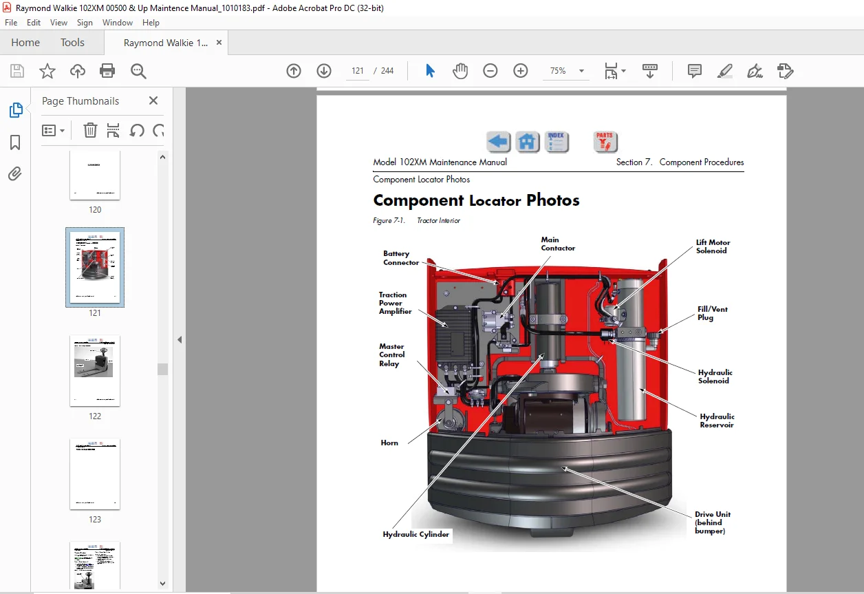
Component Locator Photos7-5
Finish and Accessories 7-7
Tractor Covers7-8
Tractor Cover Removal7-8
Tractor Cover Installation 7-8
Tractor Bumper 7-9
Bumper Removal 7-9
Bumper Installation 7-9
Model 102XM Maintenance Manual
Publication:1010183, Issued: 20 Mar 2014 vii
Steering and Controls 7-11
Control Handle Head 7-12
Control Handle Disassembly 7-13
Horn Button/Switch Replacement 7-13
Lift/Lower Button Replacement 7-14
Push Button Replacement 7-14
Emergency Reverser Replacement 7-14
Control Handle Stem 7-16
Control Handle Stem Removal 7-16
Control Handle Stem Reassembly7-17
Drive and Brake 7-19
Drive Unit Assembly 7-20
Electromagnetic Brake Assembly7-20
Brake Disc Location 7-20
Air Gap Adjustment 7-20
Friction Disc Replacement 7-21
Mechanically Releasing the Brake 7-21
Electric Brake Release Kit Installation 7-22
Drive Wheel 7-23
Drive Wheel Removal7-23
Tire Replacement7-23
Drive Wheel Installation 7-24
Drive Unit7-25
Drive Unit Removal 7-25
Drive Unit Disassembly 7-25
Drive Unit Assembly 7-26
Drive Unit Installation 7-28
Drive Unit Housing Lubrication 7-29
Gear Oil Level Check7-29
Changing Gear Oil 7-29
Electrical Components7-31
Battery 7-32
Swing-out Battery Pack 7-32
Removal (single battery) 7-32
Installation (single battery) 7-32
Removal (entire battery pack)7-32
Installation (entire battery pack) 7-33
Maintenance-Free Batteries 7-33
Battery Maintenance7-33
Battery Exterior Cleaning 7-33
Charging a Battery 7-34
Adding Water to a Battery 7-35
Battery Specific Gravity 7-35
Battery Voltage Check 7-36
Battery Storage 7-36
Power Cables 7-37
Power Cable Repair 7-37
Wiring Harness 7-39
Wiring Harness Terminology 7-39
Wiring Harness Inspection 7-39
Wiring Harness Repair 7-40
Model 102XM Maintenance Manual
viii Publication:1010183, Issued: 20 Mar 2014
Wiring Harness Soldering Procedures7-40
Fuses7-41
Fuse Test/Inspection7-41
Circuit Breaker 7-42
Circuit Breaker Test/Inspection 7-42
Horn 7-43
Horn Removal 7-43
Horn Installation7-43
Traction Power Amplifier 7-44
Cleaning the Traction Power Amplifier 7-44
Traction Power Amplifier Removal 7-44
Traction Power Amplifier Installation7-44
Contactors 7-45
Main Contactor 7-45
Main Contactor Removal7-45
Main Contactor Installation 7-45
Main Contactor, Sealed 7-45
Sealed Main Contactor Removal 7-45
Sealed Main Contactor Installation 7-46
Lift Motor Solenoid 7-46
Master Control Relay 7-47
Master Control Relay Inspection/Test7-47
Switches (General) 7-48
Testing/Inspecting Switches 7-48
Main ON/OFF Switch7-48
Main ON/OFF Switch Inspection7-48
Main ON/OFF Switch Removal 7-48
Main ON/OFF Switch Installation 7-48
Arm Angle Switches 7-49
Arm Angle Switches Adjustment7-49
Arm Angle Switches Removal7-50
Arm Angle Switches Installation 7-50
Arm Angle Switches (Plastic Switch Bridge) 7-50
Lift-Limit Switch7-53
Lift-Limit Switch Adjustment7-53
Key Switch 7-53
Key Switch Inspection 7-53
Motors, General 7-54
Motor Brush Inspection 7-54
Motor Brush Replacement 7-54
Motor Brush Spring Tension7-55
Brush Spring Tension Inspection7-55
Terminal Nuts 7-56
Traction Motor 7-57
Brush Replacement 7-57
Motor Disassembly 7-57
Traction Motor Installation 7-57
Lift Motor7-59
Lift Motor Removal 7-59
Lift Motor Installation7-59
Lift Motor Brush Replacement 7-59
Model 102XM Maintenance Manual
Publication:1010183, Issued: 20 Mar 2014 ix
Hydraulic Components7-61
Hydraulic Components 7-62
General Guidelines 7-62
Hydraulic Fluid 7-63
Hydraulic Fluid Level Check 7-63
Changing Hydraulic Fluid7-63
Hydraulic Unit7-64
Hydraulic Unit Removal 7-64
Hydraulic Unit Installation 7-64
Hydraulic Reservoir 7-65
Reservoir Removal 7-65
Reservoir Installation7-65
Filter Screen and Inlet Tube 7-66
Filter Screen and Inlet Tube Removal7-66
Filter Screen and Inlet Tube Installation 7-66
Hydraulic Pump 7-67
Hydraulic Pump Removal7-67
Hydraulic Pump Installation 7-67
Hydraulic Pump Pressure Relief Valve Adjustment7-68
Relief Valve Settings 7-68
Relief Valve Setting Check 7-68
Relief Valve Setting Adjustment 7-68
Hydraulic Cylinder 7-69
Cylinder Removal7-69
Cylinder Disassembly7-70
Cylinder Inspection 7-70
Cylinder Assembly 7-70
Cylinder Installation 7-70
Hydraulic Solenoid 7-72
Solenoid Removal7-72
Solenoid Installation 7-72
Mast 7-73
Pallet Forks and Load Wheels7-74
Load Wheels 7-74
Removal and Replacement 7-74
Load Wheel Pull Rod 7-74
Removal and Replacement 7-74
Carrier Frame Linkage 7-75
Downstops 7-76
Lower Link and Pivot Block Inspection 7-76
Downstop Adjustment 7-76
Skid Shoe Blocks7-78
Skid Shoe Adjustment 7-78
Options 7-79
Cold Storage Conditioning7-80
Cold Storage Hydraulic Fluid7-80
Theory of Operation 8-1
Definitions8-2
Acceleration 8-2
Arm Angle Switches 8-2
Click-to-Creep8-2
Model 102XM Maintenance Manual
x Publication:1010183, Issued: 20 Mar 2014
Continuity8-2
Controller Area Network (CAN)8-2
Creep Speed 8-2
Current Limiting 8-2
Deceleration (Neutral Braking)8-3
Emergency Reverse 8-3
Fault Codes 8-3
High Pedal Disable (HPD) 8-3
Open Circuit 8-3
Overvoltage Cutoff8-3
PIN-Key Code 8-3
Pulse Width Modulation 8-3
Regenerative Braking 8-3
Short Circuit or “Short” 8-3
Speed Limiting8-4
Static Return to Off (SRO)8-4
Thermal Cutback (Traction Power Amplifier) 8-4
Tractor8-4
Truck Off Delay (Keypad only)8-4
Undervoltage Cutoff 8-4
Vehicle Manager 8-4
Truck Starting 8-5
Traction System 8-6
Vehicle Manager 8-6
Power Amplifier 8-6
Direction/Speed Control 8-6
Control Handle Positioning 8-6
Travel Request8-6
Emergency Reverse 8-7
Electric Brake Release Switch8-7
Lift/Lower System 8-8
Lift8-8
Lower 8-8
AppendixA-1
Lubrication Equivalency ChartA-2
Thread Adhesives, Sealants, and Lubricants A-3
Component Specific Service/Torque ChartA-4
Torque Chart – Standard (Ferrous)A-6
Torque Chart – Standard (Brass) A-7
Torque Chart – Metric (Ferrous)A-8
Torque Chart – Metric (Brass) A-9
Torque Chart – Thread-Forming ScrewsA-9
Torque Chart – Hydraulic FittingsA-10
Torque Chart – Straight Thread Face Seal O-Rings A-11
Decimal Equivalent ChartA-12
Standard/Metric ConversionsA-14
Index I-1
IMAGES PREVIEW OF THE MANUAL:
Contact us: [email protected]
PLEASE NOTE:
- This is the same manual used by the dealers to diagnose and troubleshoot your vehicle
- You will be directed to the download page as soon as the purchase is completed. The whole payment and downloading process will take anywhere between 2-5 minutes
- Need any other service / repair / parts manual, please feel free to contact [email protected] . We still have 50,000 manuals unlisted
S.V